WIN Enterprises PC/104-PLUS User manual

1
User’s Manual
Version 1.2
PC/104-PLUS Module
Model Number MB-73030
AMD Geode LX800 Low Power PC/104+ SBC with VGA/LCD, Two 10/100 LAN,
Audio & SSD

2
Table of Contents
Chapter 1. General Information ......................................................................3
1-1. Introduction..............................................................................................3
1-2. Specification.............................................................................................3
1-3. MB-73030 Package...................................................................................4
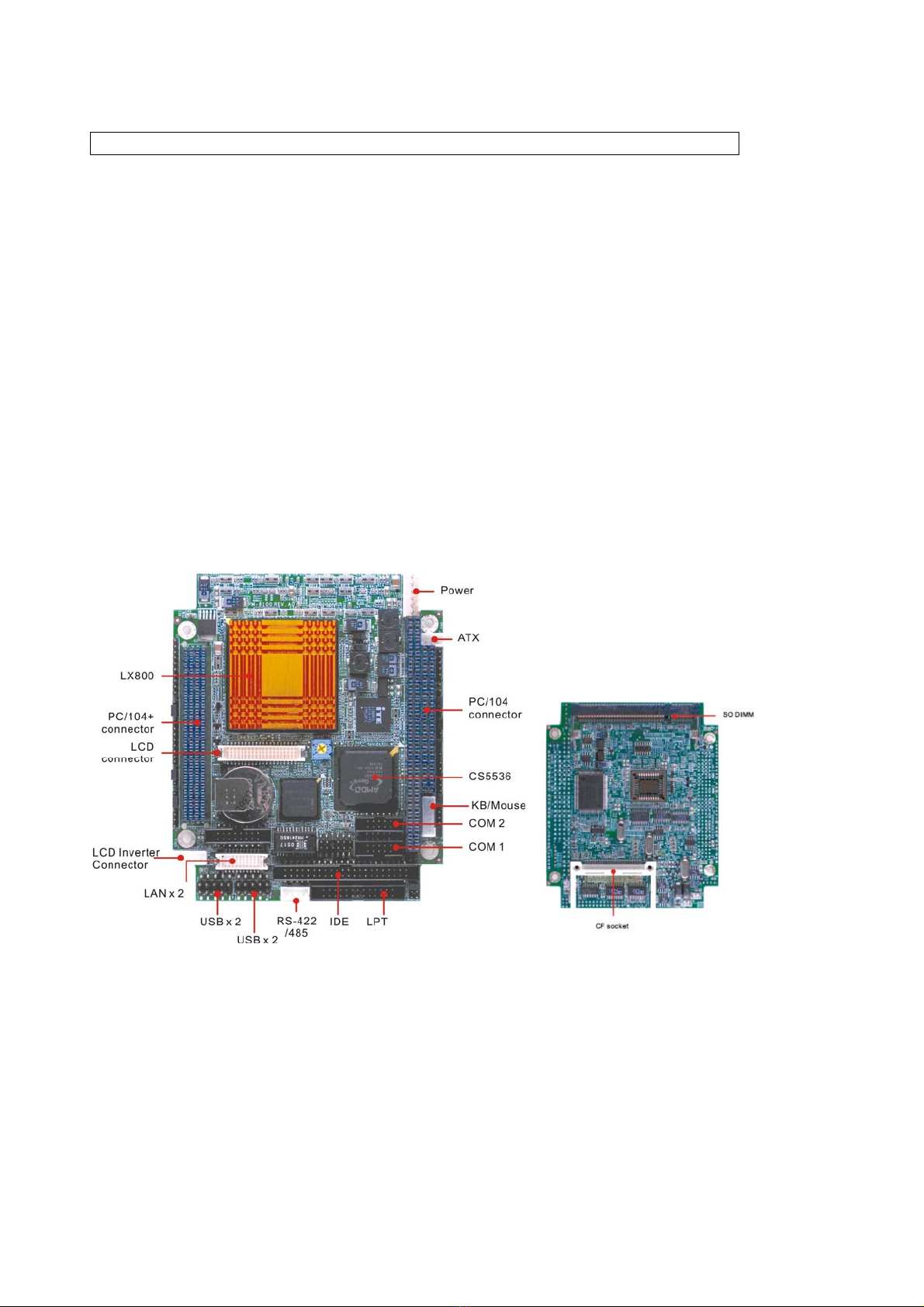
1-4. Board Layout............................................................................................5
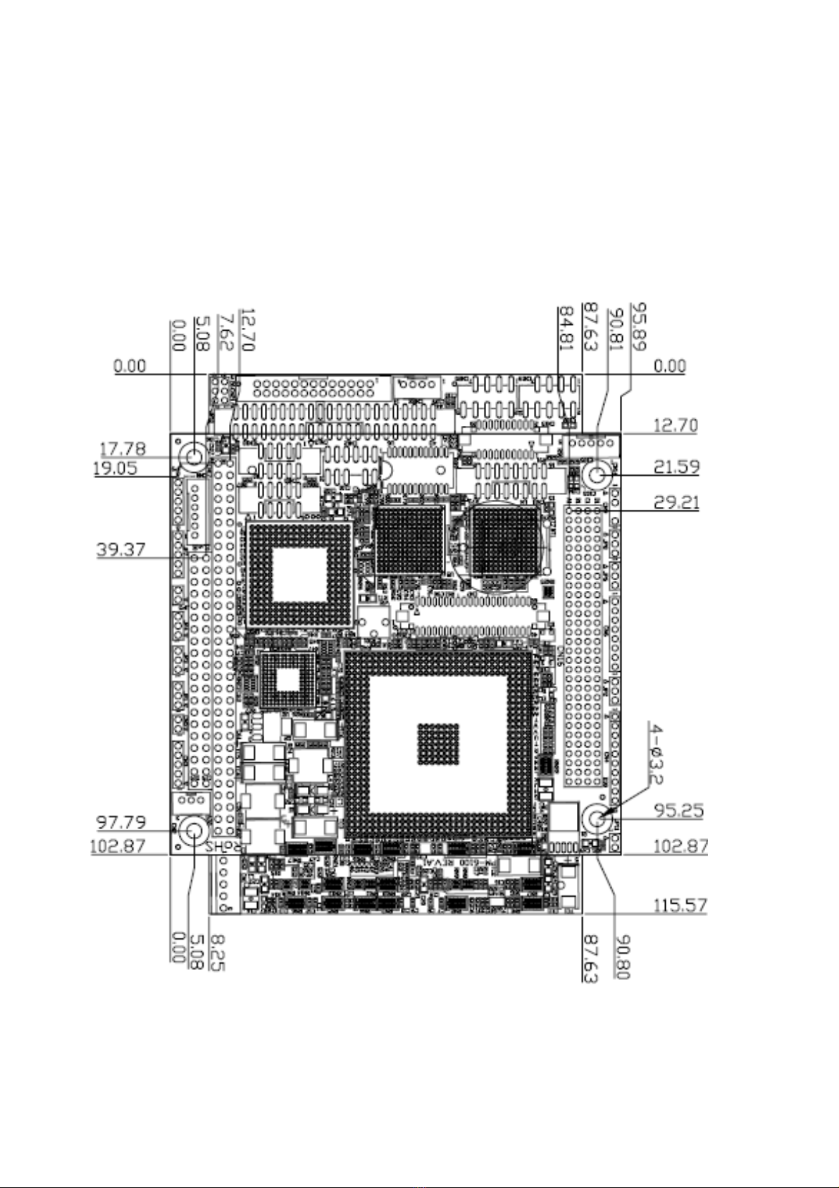
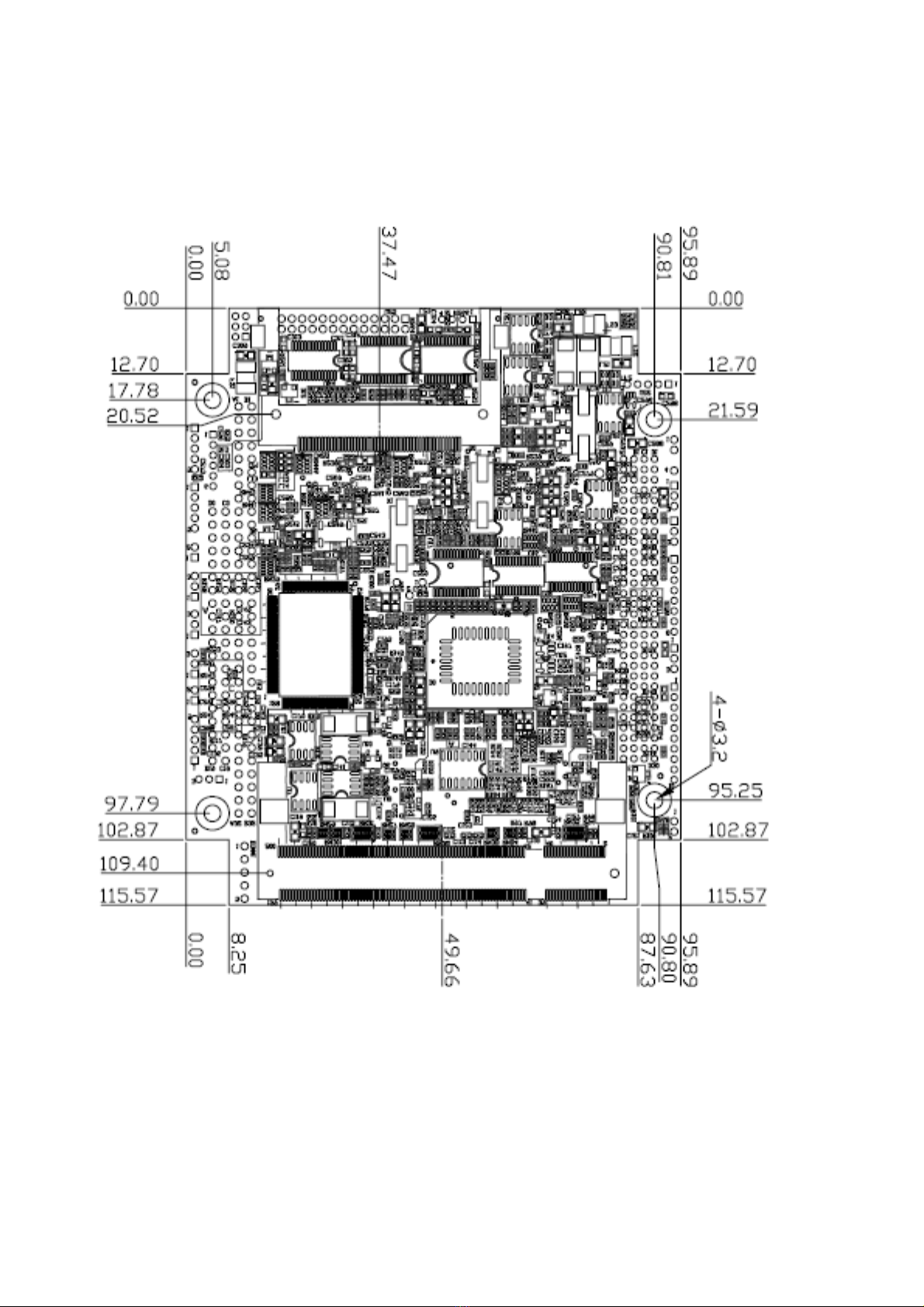
1-5. Board Dimension .....................................................................................6
Chapter 2. Installation .....................................................................................8
2-1. Location of Connectors...........................................................................8
2-2. List of Connectors ...................................................................................8
2-3. Location of Jumpers................................................................................9
2-4. List of Jumpers ........................................................................................9
2-5. Connector Pin Assignment and Jumper Settings...............................10
Chapter 3. BIOS Setup......................................................................................18
3.1 Quick Setup .............................................................................................18
3.2 Entering the CMOS Setup Program.......................................................18
3.3 Menu Options ..........................................................................................19
3.4 Advanced BIOS Features Setup.............................................................22
3.5 Advanced Chipset Features Setup ........................................................24
3.6 Integrated Peripherals Setup .................................................................24
3.7 Power Management Setup......................................................................30
3.8 PNP/PCI Configuration ...........................................................................31
3.9 PC Health Status .....................................................................................33
3.10 Load Fail-Safe Defaults.........................................................................34
3.11 Load Optimized Defaults.......................................................................35
3.12 Supervisor/User Password...................................................................35
Appendix A: Programming the Watchdog Timer ...........................................38
Appendix B: System Resource........................................................................40
Appendix C: Installing CompactFlash Memory..............................................42
Appendix D: Cable List.....................................................................................43

3
Chapter 1. General Information
1-1. Introduction
The MB-73030 is a full function of the PC/104+ embedded format SBC board using the
AMD CS5536 chipset, it supports the AMD LX800 500 MHz processor. The MB-73030
supports CRT, 24-bit TFT panels, one Ultra ATA-66 IDE devices, one CF socket, the
Dual Intel® 82551ER Ethernet chipset and an AC-97 Audio Interface.
The onboard features include one RS-232 and one RS-232/422/485 serial port, one
bi-directional parallel port, four USB 2.0 ports, also a watchdog timer and PC/104+
( both PCI & ISA) connector for flexible expansion capabilities. In addition, the onboard
SSD interface supports a 50-pin CompactFlash™ socket for TypeI/II CompactFlash
Cards and a memory support 200-pin DDR SO-DIM.
1-2. Specification
Specifications
General Functions
CPU AMD Geode LX800 processor
BIOS Insyde® 512KB Flash BIOS
Chipset AMD CS5536
I/O Chipset Winbond 83627HG
Memory One 200-pin DDR SO-DIMM socket support up to 1GB DDR
333/400 Memory
Enhanced IDE Support up to one Ultra ATA-66 IDE devices
Parallel port Support SPP/ECP/EPP
Serial port One RS-232 and one RS-232/422/485 serial ports.
IR interface Support one IrDATx/Rx header
KB/Mouse connector keyboard/ mouse pin-header
USB connectors Support four USB 2.0 ports( two on external Connector, two
on Pin-header)
Battery Lithium battery for data retention up to 10 years(in normal
condition)
Watchdog Timer Software programmable, 1-255 level
PC/104+ Connector PC/104+ connectors for both PCI & ISA
Power management APM 1.2 compliant
Flat Panel/CRT Interface
VGA Chipset AMD Geode LX-800
Display memory Share system memory 2~254MB
Display type Simultaneous supports CRT and 24-bit TFT LCD
Resolution CRT Resolution support up to 1920 x 1440 @ 32bpp or
1660 x1200 @ 32bpp CRT & LCD simultaneous: up to 1024
x 768 @ 18bpp (60Hz)

4
Ethernet Interface
Chipset Dual Intel 82551ER
Ethernet interface PCI 100/10 Mbps Ethernet controller
SSD Interface One 50-pin CompactFlash™ socket
Sound Adaptor (optional R-031)
Chipset OptionalAC 97 codec
Audio controller SoundBlaster Pro Hardware and Direct Sound Ready AC97
Digital Audio
Audio interface Mic in and Speaker out
Software Driver Supports for Windows 95, Windows 98 and windows NT
Mechanical and Environmental
Power supply voltage VCC (4.75V to 5.25V),
Max. power requirements +5 V @2.2A,
Operating
temperature 32 to 140°F (0 to 60°C)
Board size 95.9mm x115.6mm
Weight 0.6 lb. (0.3 Kg) Net Weight
1-3. MB-73030 Package
Please make sure that the following items have been included in the package before
installation.
MB-73030 PC/104+ Embedded SBC board
Quick Installation Guide
Cables
oIDE Cable
oCOM Cable
oPower Cable(ATX 20P)
oKB/Mouse Cable
oUSB Cable
oVGA Cable
oDual LAN Adaptor R051
oLAN Cable between R051 & MB-73030
CD-ROM which contains the following folders:
oManual (in PDF format)
oLAN Driver
oVGA Driver
oAudio Driver
oBIOS Utility
If any of these items are missing or damaged, please contact your dealer at once.
Save the shipping materials and carton for shipping or storage the board. After you
unpack the board, inspect it to assure an intact shipment. Press down all the
integrated circuits to make sure they are properly seated in their sockets. Do not apply
power to the board if it appears to have been damaged.

5
Leave the board in its original packing until you are ready to install
Precautions
Please make sure you properly ground yourself before handling the MB-73030 board or
other system components. Electrostatic discharge can be easily damage the
MB-73030 board.
Do not remove the anti-static packing until you are ready to install the MB-73030 board.
Ground yourself before removing any system component from it protective anti-static
packaging. To ground yourself, grasp the expansion slot covers or other unpainted
parts of the computer chassis.
Handle the MB-73030 board by its edges and avoid touching its component.
1-4. Board Layout

6
1-5. Board Dimension
Board Dimension (mm) (Component Side)

7
Board Dimension (mm) (Solder Side)

8
Chapter 2. Installation
2-1. Location of Connectors
2-2. List of Connectors
Connectors Description Connectors Description
CN1 Main Power Connector CN12 AC 97 Audio Connector
CN2 ATX Power Connector CN13 COM1 Connector (Pin Header)
CN3 IR Connector CN14 Flat Panel Inverter Connector
CN4 GPIO Connector CN15 LAN Connector
CN5 ATX Power Control Connector CN16 PC/104 Plus Connector( PCI)
CN6 Power LED /HDD
LED/Reset/Speak Out Connector CN17 PC/104 Connector
CN7 Flat Panel Connector CN18 IDE Connector 44pin
CN8 KB/Mouse Connector CN19 USB 1/2 Connector(Pin Header)
CN9 Auxiliary Power Connector CN20 USB 3/4 Connector(Pin Header)
CN10 COM2 Connector (Pin Header) CN21 Parallel Connector(Pin Header)
CN11 VGA Connector (Pin Header) CN22 COM2 –RS422/RS485 Connector
(Pin Header)

9
2-3. Location of Jumpers
2-4. List of Jumpers
Pin Define Pin Define
JP1 Memory Speed Selection JP6 Watchdog Select
JP2 LCD Panel Voltage Select JP7 COM2 RI/Voltage Select
JP3 AT/ATX Power Select(5VSB) JP8 Clear CMOS
JP4 AT/ATX Power Select JP9 COM1 RI/Voltage Select
JP5 CF Slave/Master JP10 COM2 RS-232/422/485 Selec
JP11 DDR 2.6V/2.5V Voltage Select

10
2-5.Connector Pin Assignment and Jumper Settings
CN1: Main Power Connector Pin Assignment
1 +5V
2 +5V
3 Ground
4 Ground
5 +12V
CN2: ATX Power Connector
Pin Assignment
1 5V Standby
2 Ground
3 PS_On
CN3: IR Connector
The IrDA connector (CN24) can be configured to support a wireless infrared module.
With this module and application software such as Laplink or a WIN95/98 direct cable
connection, you can transfer files to or from Loptops, Notebooks, PDAs, and printers.
This connector supports HPSIR (115.2kbps, 2 meters) and ASK-IR (56Kbps). Connect
an infrared module to the IrDA connector and enable the infrared function in the BIOS
setup. Pin Assignment
1 Vcc
2 NC
3 IR Receiver
4 Ground
5 IR Transmitter
CN4 GPIO Connector Pin Assignment
1 +5V
2 GPI1
3 GPI2
4 GPI3
5 GPI4
6 GPO1
7 GPO2
8 GPO3
9 GPO4
10 Ground

11
CN5: ATX Power Control Connector Pin Assignment
1 PANSW-
2 PANSW+
CN6: Power LED /HDD LED/Reset/Speak Out Connector Pin Assignment
1 Power LED+
2 Power LED-
3 HDD LED+
4 HDD LED-
5 Reset +
6 Reset -
7 Speak Out+
8 Speak Out-
CN7: Flat Panel Connector Pin Signal Pin Signal
1 +12V 2 +12V
3 Ground 4 Ground
5 Vcc LCD 6 Vcc LCD
7 PRST# 8 Ground
9 LCD-B0 10 LCD_B1
11 LCD_B2 12 LCD_B3
13 LCD_B4 14 LCD_B5
15 LCD_B6 16 LCD_B7
17 LCD_G0 18 LCD_G1
19 LCD_G2 20 LCD_G3
21 LCD_G4 22 LCD_G5
23 LCD_G6 24 LCD_G7
25 LCD_R0 26 LCD_R1
27 LCD_R2 28 LCD_R3
29 LCD_R4 30 LCD_R5
31 LCD_R6 32 LCD_R7
33 Ground 34 Ground
35 DOTCLK 36 FPVSYNC
37 DE 38 FPHSYNC
39 VDDEN 40 FPBKLEN
CN8: Keyboard/Mouse Connector Pin Assignment
1 KBCLK#
2 KBDATA#
3 MSCLK#
4 Ground
5 +5V
6 MSDATA#

12
CN9: Auxiliary Power Connector
The MB-73030 supports an auxiliary power connector that includes –5V and –12V
voltages. It supports some PCI add-on cards or PC/104 modules that needs these
voltages. Please connect the auxiliary power cable to CN9 and the power supply DC
connector. Pin Assignment
1 -5V
2 Ground
3 Key pin
4 -12V
CN13, CN10: COM1, COM2 RS-232 Pin-Header
Pin Assignmen
t Pin Assignment
1 DCD 2 DSR
3 RXD 4 RTS
5 TXD 6 CTS
7 DTR 8 RI
9 Ground 10 NC
CN11: VGA Connector (Pin Header)
Pin Signal Pin Signal
1 RED 2 GREEN
3 BLUE 4 +5V
5 Ground 6 Ground
7 Ground 8 Ground
9 +5V 10 Ground
11 +5V 12 DDC Data
13 H-SYNC 14 V-SYNC
15 DDC Clock 16 NC
CN12: Audio Connector
This connector is used to connect a CD Audio cable, depending on the type of installed
CD-ROM drive, connect the CD-ROM drive cable to one of these 12-pin connectors.
Pin Assignment Pin Assignment
1 +5V 2 Ground
3 Ground 4 CLKBIT
5 +3.3V 6 Key Pin
7 SDTAIN 8 SYNC
9 Ground 10 PRST#
11 SDATAOUT 12 NC
CN14: Flat Panel Inverter Connector Pin Assignment
1 +12V
2 Ground
3 FPBKLEN
4 VR
5 +5V

13
CN15: LAN Connector Pin Signal Pin Signal
1 Lan1-Speed 2 Lan2-Speed
3 Lan1-Act 4 Lan2-Act
5 Lan1-Link 6 Lan2-Link
7 +3.3V 8 Ground
9 Lan-Ground 10 Lan-Ground
11 Lan1-TX+ 12 Lan1-RX+
13 Lan1-TX- 14 Lan1-RX-
15 Ground 16 Ground
17 Lan2-TX+ 18 Lan2-RX+
19 Lan2-TX- 20 Lan2-RX-
CN16: PC/104 Plus Connector
Signal Pin Signal Pin Signal Pin Signal Pin
Ground A1 NC B1 +5V C1 AD00 D1
VIO A2 AD02 B2 AD01 C2 +5V D2
AD05 A3 Ground B3 AD04 C3 AD03 D3
C/BE0# A4 AD07 B4 Ground C4 AD06 D4
Ground A5 AD09 B5 AD08 C5 Ground D5
AD11 A6 VIO B6 AD10 C6 M66EN D6
AD14 A7 AD13 B7 Ground C7 AD12 D7
+3.3V A8 C/BE1# B8 AD15 C8 +3.3V D8
SERR# A9 Ground B9 SBO# C9 PAR D9
Ground A10 PERR# B10 +3.3V C10 SDONE D10
STOP# A11 +3.3V B11 LOCK# C11 Ground D11
+3.3V A12 TRDY# B12 Ground C12 DEVSEL# D12
FRAME# A13 Ground B13 IRDY# C13 +3.3V D13
Ground A14 AD16 B14 +3.3V C14 C/BE2# D14
AD18 A15 +3.3V B15 AD17 C15 Ground D15
AD21 A16 AD20 B16 Ground C16 AD19 D16
+3.3V A17 AD23 B17 AD22 C17 +3.3V D17
IDSEL0 A18 Ground B18 IDSEL1 C18 IDSEL2 D18
AD24 A19 C/BE3# B19 VIO C19 IDSEL3 D19
Ground A20 AD26 B20 AD25 C20 Ground D20
AD29 A21 +5V B21 AD28 C21 AD27 D21
+5V A22 AD30 B22 Ground C22 AD31 D22
REQ0# A23 Ground B23 REQ1# C23 VIO D23
Ground A24 REQ2# B24 +5V C24 GNT0# D24
GNT1# A25 VIO B25 GNT2# C25 Ground D25
+5V A26 CLK0 B26 Ground C26 CLK1 D26
CLK2 A27 +5V B27 CLK3 C27 Ground D27
Ground A28 INTD# B28 +5V C28 RST# D28
+12V A29 INTA# B29 INTB# C29 INTC# D29
-12V A30 NC B30 NC C30 Ground D30

14
CN17: PC/104 Connector
CN17 is a standard PC/104 bus connector, and it is fully occupied with the signals of the
“ISA” (PC/AT) bus. It offers full architecture, hardware and software compatibility with
the ISA bus and can accept ultra-compact (3.6” x 3.8”) stackable modules.
Signal Pin Signal Pin Signal Pin Signal Pin
Ground C0 Ground D0 IOCHCHK A1 Ground B1
SBHE* C1 MEMCS16* D1 SD7 A2 RESET B2
LA23 C2 IOSC16* D2 SD6 A3 +5V B3
LA22 C3 IRQ10 D3 SD5 A4 IRQ9 B4
LA21 C4 IRQ11 D4 SD4 A5 -5V B5
LA20 C5 IRQ12 D5 SD3 A6 NC B6
LA19 C6 IRQ15 D6 SD2 A7 -12V B7
LA18 C7 IRQ14 D7 SD1 A8 0 wait state B8
LA17 C8 NC D8 SD0 A9 +12V B9
MEMR* C9 NC D9 IOCHRDY A10 NC B10
MEMW* C10 NC D10 AEN A11 SMEMW# B11
SD8 C11 NC D11 SA19 A12 SMEMR* B12
SD9 C12 NC D12 SA18 A13 IOW* B13
SD10 C13 NC D13 SA17 A14 IOR* B14
SD11 C14 NC D14 SA16 A15 NC B15
SD12 C15 NC D15 SA15 A16 NC B16
SD13 C16 +5V D16 SA14 A17 NC B17
SD14 C17 MASTER* D17 SA13 A18 NC B18
SD15 C18 Ground D18 SA12 A19 REFRESH* B19
NC C19 Ground D19 SA11 A20 SYSCLK B20
SA10 A21 IRQ7 B21
SA9 A22 IRQ6 B22
SA8 A23 IRQ5 B23
SA7 A24 IRQ4 B24
SA6 A25 IRQ3 B25
SA5 A26 NC B26
SA4 A27 TC B27
SA3 A28 BALE B28
SA2 A29 +5V B29
SA1 A30 OSC B30
SA0 A31 Ground B31
Ground A32 Ground B32
CN18: IDE Connector
You are able to configure two hard disks to Master mode by using one ribbon cable on
the primary IDE connector and another on the secondary IDE connector.
Pin Signal Pin Signal
1 Reset 2 Ground
3 Data7 4 Data8
5 Data6 6 Data9
7 Data5 8 Data10

15
9 Data4 10 Data11
11 Data3 12 Data12
13 Data2 14 Data13
15 Data1 16 Data14
17 Data0 18 Data15
19 Ground 20 NC
21 DREQ 22 Ground
23 IOW# 24 Ground
25 IOR# 26 Ground
27 IRDY 28 Ground
29 DACK# 30 Ground
31 IRQ14 32 NC
33 Address 1 34 Detect
35 Address 0 36 Address 2
37 Select 0 38 Select 1
39 Active 40 Ground
41 +5V 42 +5V
43 Ground 44 NC
CN19, CN20: USB1/2, USB3/4 Connector(Pin Header)
Pin Assignment Pin Assignment
1 +5V 2 +5V
3 Data0- 4 Data1-
5 Data0+ 6 Data1+
7 Ground 8 Ground
9 Key Pin 10 Ground
CN21: Parallel Port Connector Pin Assignment Pin Assignment
1 STRPBE 14 AUTOFD
2 PD0 15 ERR
3 PD1 16 INIT
4 PD2 17 SLCTIN
5 PD3 18 Ground
6 PD4 19 Ground
7 PD5 20 Ground
8 PD6 21 Ground
9 PD7 22 Ground
10 ACK# 23 Ground
11 BUSY 24 Ground
12 PE 25 Ground
13 SLCT 26 Ground
CN22: COM2 –RS422/RS485 Connector(Pin Header) Pin Assignment
1 485RXD-
2 485RXD+
3 485TXD+
4 485TXD-

16
JP1: Memory Speed Selection
Setting Define
1-2 400
2-3 333(Default)
JP2: LCD Panel Voltage Select
Setting Define
1-2 +3.3V(Default)
2-3 +5V
JP3: AT/ATX Power Select(5VSB)
Setting Define
1-2 AT
2-3 ATX(Default)
JP4: AT/ATX Power Select
Setting Define
1-2 AT
2-3 ATX(Default)
JP5: CF Master/Slave Select
Setting Define
1-2 Master(Default)
NC Slave
JP6: Watchdog Time Mode Select
Setting Define
1-2 IRQ11
2-3 Reset Switch
(Default)

17
JP7/9: COM2/1 RI/Voltage Select
Setting Define
1-2 Ring(Default)
2-3/3-4 +5V
4-5 +12V
JP8: CMOS Clear
Setting Define
1-2 Normal Status(Default)
2-3 Clear CMOS
JP10: COM2 RS-232/422/485 Selector (Default: RS-232)
Setting COM Ports
1-2 RS-232(Default)
3-4 RS-422
5-6 RS-485
JP11: DDR 2.6V/2.5V Voltage Select
Setting Define
1-2 2.6V_DDR400
NC 2.5V_DDR333(Default)

18
Chapter 3. BIOS Setup
The ROM chip of your MB-73030 board is configured with a customized Basic
Input/Output System (BIOS) from Phoenix-Award BIOS. The BIOS is a set of
permanently recorded program routines that give the system its fundamental operational
characteristics. It also tests the computer and determines how the computer reacts to
instructions that are part of programs.
The BIOS is made up of code and programs that provide the device-level control for the
major I/O devices in the system. It contains a set of routines (called POST, for Power-On
Self Test) that check out the system when you turn it on. The BIOS also includes CMOS
Setup program, so no disk-based setup program is required CMOS RAM stores
information for:
1. Date and time
2. Memory capacity of the main board
3. Type of display adapter installed
4. Number and type of disk drives
The CMOS memory is maintained by battery installed on the MB-73030 board. By using
the battery, all memory in CMOS can be retained when the system power switch is
turned off. The system BIOS also supports easy way to reload the CMOS data when you
replace the battery of the battery power lose.
3.1 Quick Setup
In most cases, you can quickly configure the system by choosing the following main
menu options:
1. Choose “Load Optimized Defaults” from the main menu. This loads the setup
default values from the BIOS Features Setup and Chipset Features Setup screens.
2. Choose “Standard COS Features” from the main menu. This option lets you
configure the date and time, hard disk type, floppy disk drive type, primary display
and more.
3. In the main menu, press F10 (“Save & Exit Setup”) to save your changes and reboot
the system.
3.2 Entering the CMOS Setup Program
Use the CMOS Setup program to modify the system parameters to reflect the options
installed in your system and to customized your system. For example, you should run
the Setup program after you:
1. Received an error code at startup
2. Install another disk drive
3. Use your system after not having used it for a long time
4. Find the original setup missing
5. Replace the battery
6. Change to a different type of CPU
7. Run the Phoenix-Award Flash program to update the system
BIOS
Run the CMOS Setup program after you turn on the system. On-screen
instructions explain how to use the program.

19
Enter the CMOS Setup program’s main menu as follows:
1. Turn on or reboot the system. After the BIOS performs a series of diagnostic
checks, the following message appears:
“Press DEL to enter SETUP”
2. Press the <DEL> key to enter CMOS Setup program. The main menu
appears:
3. Choose a setup option with the arrow keys and press <Enter>. See the
following sections for a brief description of each setup option.
In the main menu, press F10 (“Save & Exit Setup) to save your changes and reboot
the system. Choosing “EXIT WITHOUT SAVING” ignores your changes and exits
the program. Pressing <ESC> anywhere in the program returns you to the main
menu.
3.3 Menu Options
The main menu options of the CMOS Setup program are described in the following and
the following sections of this chapter.
Option Function
Standard CMOS Features This setup page includes all the items in standard
compatible BIOS
Advanced BIOS features This setup page includes all the item of Award
special enhanced features.
A
dvanced Chipset Features This setup page includes all the items of chipset
special features.
Integrated Peripherals This setup page includes all onboard peripherals.

20
Power Management Setup This setup page includes all the items of Green
function features.
PnP/PCI Configurations
This setup page includes all the configurations of
PCI & PnP ISA resources.
PC Health Status
This setup page is the System auto detect
including temperature, voltage, fan, speed .
Load Fail-Safe Defaults Fail-Safe Defaults are the BIOS default values for
the minimal/stable performance for your system to
operate.
Load Optimized Defaults Optimized Defaults are the factory setting for
optimal performance system operations.
Set Supervisor password Change, set, or disable password, It allows you to
limit access to the system and Setup,or just to
Setup.
Set User password Change, Set, or disable password, It allows you to
limit access to the system.
Save & Exit Setup Save CMOS value setting to CMOS and exit
setup.
Exit Without Saving Abandon all CMOS value changes and exit setup.
Use the Standard CMOS Setup option as follows:
1. Choose “Standard CMOS Features” from the main menu. The following screen
appears:
2. Use the arrow keys to move between fields. Modify the selected field using the
PgUP/PgDN/+/- keys. Some fields let you enter numeric values directly.
This manual suits for next models
1
Table of contents
Other WIN Enterprises Control Unit manuals