WIN Enterprises IP-06060 User manual

Quick Installation Guide
V 1.0
Model: IP-06060
AMD Geode LX800 Low Power 3.5” Embedded SBC with
VGA/LCD, Two 10/100LAN, Audio & SSD

Chapter 1. General Information
1-1. Introduction
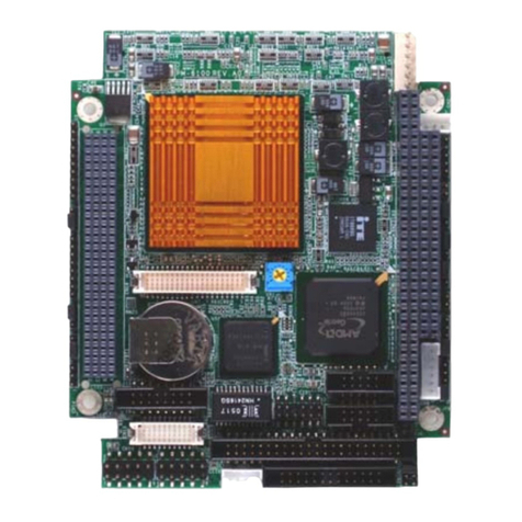
The IP-06060 is a full function of the 3.5” embedded format SBC board that uses the AMD CS5536
chipset to support the LX800 500 MHz processor. The IP-06060 supports CRT and 24-bit TFT panels, two
Serial ATA, two Ultra ATA-133 IDE devices, Dual Intel® 82551ER (or Realtek RLT8139CL+); an
Ethernet chipset with two RJ45 jacks for 10/100Mbps and an AC-97 Audio Interface.
Onboard features include three RS-232 and one RS-232/422/485 serial ports, one bidirectional parallel
port, four USB 2.0 ports, also contains a watchdog timer and PC/104 connector for flexible expansion
capabilities. In addition, the onboard SSD interface supports 50-pin CompactFlash socket for TypeI/II
CompactFlash Cards and memory support 200-pin DDR SO-DIM.
1-2. Specifications
System
CPU AMD® Geode™ LX800 , 500MHz
BIOS Award® 512KB Flash BIOS
System Chipset AMD® Geode™ CS5536
System Memory Onboard 1 x 200-pin DDR SO-DIMM socket supports DDR 333/400 max. up to 1GB
Power Management APM 1.2; ACPI supported
SSD 50-pin CompactFlash™ type II socket
(DMA mode CompactFlash™ )
Watchdog Timer 255 levels timer interval, (1 ~ 255 seconds), setup by software. Jumper set up for system reset
or IRQ
Expansion
Interface PC/104 connector for ISA ( No ISA bus master & PnP)
Battery Lithium 3V/220mAH
I/O
I/O Chipset Winbond® 83627HG
I/O Interface 1 x EIDE (Ultra ATA-66), 1 x PS/2 KB/Mouse, 3 x RS-232, 1 x RS-232-422/485,
1 x IrDA
USB 4 x USB ports, USB 2.0 compliant
Audio
(optional Audio
module R-031)
Supports AC 97 audio stereo sound ( Mic. in & Speaker out)
GPIO 8-bit TTL input & 8-bit TTL output
Ethernet Interface
Chipset Intel® 82551ER or Realtek 8139CL+

Speed 10/100Mbps
Interface 2 x RJ-45
Standard IEEE802.3u (100Base-T) protocol compatible
Display
Chipset AMD® Geode™ LX800
Memory Size 2 ~ 254MB frame buffer sharing system memory
Resolution CRT mode:
■1920 x 1440 x 32 bpp at 85Hz
■1600 x 1200 x 32 bpp at 100Hz
LCD/LVDS
Interface
LCD/Simultaneous mode: 1024 x 768 x 16 bpp at 60Hz
LVDS: 18/24-bit LVDS supports via optional R-053A/B
Dual Independent
Display CRT + LCD or CRT+ LVDS
Mechanical and Environmental
Dimension ( L x W )
145mm (L) x 102mm(W) (5.7"L x 4"W )
Operating
Temperature 0 ~ 60°C (32 ~ 140°F)
Operating Humidity
10% ~ 95% relative humidity, non-condensing
Power
Power Supply
Voltage Single +5V power in, AT/ATX power control
Power
Consumption LX-800 (500MHz)@256MB DDR266 Max (XP, Vpower):12W, +5V @2.4A
Ordering Information
IP-6060A 3.5" SBC with AMD® Geode™ LX800, VGA, LCD, 2 LANs (Intel® 82551ER), Audio & SSD
IP-6060B 3.5" SBC with AMD® Geode™ LX800, VGA, LCD, 2 LANs (Realtek® 8139CL+), Audio & SSD
(by order)
IP-6060C 3.5" SBC with AMD® Geode™ LX800, PC/104, VGA, LCD, 2 LANs (Intel® 82551ER), Audio &
SSD
IP-6060D 3.5" SBC with AMD® Geode™ LX800, PC/104, VGA, LCD, 2 LANs (Realtek® 8139CL+), Audio
& SSD (by order)
Optional
DK-01023 Audio kit w/ Mic. in & Speaker out
R-053A LVDS kit supports 18-bit
R-053B LVDS kit supports 24-bit
CB-ICOM01-00 COM port cable (2mm) 13cm/RoHS
CB-IUSB03-00 USB cable 2 x 5 (2mm)/ RoHS
CB-ILPT01-00 Printer cable (2mm) 26cm/RoHS

Included Parts (Ships with Product)
1 x IP-60600 SBC
1 x IDE cable (p/n: CB-I00IDE-00)
1 x I/O cable ( p/n:CB-ICOM-02-00)
1 x KB/MS cable (p/n:CB-IPS266-00)
1 x Vertical type to 4P power cable (p/n:CB-IPOW30-00)
User’s Manual; s/w drivers from FTP download
*NOTE: The ITE8888G PCI to ISA bridge for PC/104 slot uses PC/PCI DMA (PPDMA) for ISA bus master. The Geode LX800
Chipset uses the CS5536 south bridge
1-3. IP-06060 Packaging
Please make sure that the following items have been included in the package before installation.
•IP-06060 3.5” Embedded SBC board
•Quick Installation Guide
•Cables (Please refer Appendix D)
•CD-ROM which contains the following folders:
oManual (in PDF format)
oLAN Driver
oVGA Driver
oAudio Driver
oBIOS Utility
If any of these items are missing or damaged, please contact the dealer from whom you
purchased the board at once. Save the shipping materials and carton in the event that

you want to ship or store the board in the future. After you unpack the board, inspect it to
assure an intact shipment. Press down all the integrated circuits to make sure they are
properly seated in their sockets. Do not apply power to the board if it appears to have
been damaged. Leave the board in its original packing until you are ready to install.
Precautions
Make sure you properly ground yourself before handling the IP-06060 board or other
system components. Electrostatic discharge can be easily damage the IP-06060
board.
Do not remove the anti-static packing until you are ready to install the IP-06060 board.
Ground yourself before removing any system component from its protective anti-static
packaging. To ground yourself, grasp the expansion slot covers or other unpainted parts
of the computer chassis.
Handle the IP-06060 board by its edges and avoid touching its components.
1-4. Board Layout 1-5. Board Dimension

Board Dimension (mm)
(Component Side)

Board Dimension (mm) (Solder Side)

Chapter 2. Installation
2-1. Location of Connectors
(Component Side)

(Solder Side)
2-2. List of Connectors
Connectors Description Connectors Description
CN1 ATX Power Connector CN15 Power/LED Connector
CN2 Main Power Connector CN16
CN3 USB 1/2 Connector CN17 USB 3/4 Connector
CN4 LAN1 Connector (RJ45) CN18 Reset Switch
CN5 Parallel Connector CN19 ATX Power Control Connector
CN6 LAN2 Connector (RJ45) CN20 PC/104 Connector
CN7 COM2 Connector (Pin
Header) CN21 COM3 Connector (Pin Header)
CN8 VGA Connector (D-Sub) CN22 COM4 Connector (Pin Header)
CN9 Flat Panel Connector CN23 KB/Mouse Connector
CN10 S-ATA Connector CN24 IR Connector
CN11 IDE Connector 44pin CN25 Auxiliary Power Connector
CN12 AC 97 Audio Connector D4 Power LED
CN13 COM1 Connector (D-Sub) D5 HDD LED
CN14 GPIO Connector

2-3. Location of Jumpers
Connector Pin Assignment and Jumper Settings

CN1: ATX Power Connector
The IP-06060 supports a soft-power switch function if an ATX power supply is used. Note:
Enable the soft power switch as follow: Connect the ATX-to-PS/2 power cable to CN1 and the
ATX DC power connector
CN2: Main Power Connector
CN3: USB Connector The IP-06060 supports Four USB (Universal Serial Bus) ports, which give
complete plug and play, hot attach/detach for up to 127 external devices. The USB interface
complies with USB specification Rev. 1.0 and can be disabled in the system BIOS setup.
CN4, CN6: LAN1/LAN2 10/100BaseT RJ-45 Connector
The IP-06060 features onboard dual Ethernet RJ-45 connectors, the onboard Intel® 82559ER or
Realtek RTL8139C+ fast Ethernet controller supports 10Mbps and 100Mbps N-Way auto-
negotiation operations.

CN5: Parallel Port Connector
The IP-06060 supports one parallel port, accessed through CN5. You need an adapter cable if
you use a traditional DB-25 connector. The cable has a 26-pin connector on one end and a DB25
connector on the other. The port is designed as LPT1 and can be disabled or changed to LPT2 or
LPT3 in the BIOS Integrated Peripherals setup. You also can select the ECP/EPP mode in the
BIOS Integrated Peripherals setup.
CN7: COM2 RS-232/422/485 PIN-Header

CN8: VGA Connector
The IP-06060 supports a standard D-SUB VGA connector for CRT display.
CN9: Flat Panel Connector

CN10 S-ATA Connector
CN11: IDE Connector
You are able to configure two hard disks to Master mode by using one ribbon cable on the
primary IDE connector and another on the secondary IDE connector.

CN12: Audio Connector
This connector is used to connect a CD Audio cable, depending on the type of installed CD-ROM
drive; connect the CD-ROM drive cable to one of these 12-pin connectors.
CN13, CN7, CN21, CN22: Serial Ports
The IP-06060 supports four serial ports: three RS-232 (COM1/COM3/COM4) and one RS-
232/422/485 (COM2). The COM1(CN13) is D-Sub connector and COM2/COM3/COM4 are pin
header type. These ports allow you to connect serial devices such as mouse, printer and more.
You need an adapter cable if you use a traditional DB-9 connector for COM2/COM3/COM4. The
COM2 cable has 14-pin and COM3/COM4 has 10-pin.
The COM2 designed as RS232 and can be changed to RS-422/485 in the JP5.
CN14 GPIO Connector

CN15: Power LED/ HDD LED Connector CN17: USB Connector
The IP-06060 supports four USB ports, CN17 with 2.0mm pitch pin header for USB3/4, which
give complete plug and play, hot attach/detach for up to 127 external devices. The USB interface
complies with USB specification Rev. 1.0 and can be disabled in the system BIOS setup.
CN19: ATX Power Control Connector CN20: PC/104 Connector
CN20 is a standard PC/ 104 bus connector and it is fully occupied with the signals of the “ISA”
(PC/AT) bus. It offers full architecture, hardware and software compatibility with the ISA bus

See how to install the PC/104 module in Appendix C.
CN21, CN22: COM3, COM4 Pin-Header Connector

CN24: IR Connector The IrDA connector (CN24) can be configured to support a wireless
infrared module. With this module and application software such as Laplink or a WIN95/98 direct
cable connection, you can transfer files to or from Laptops, Notebooks, PDAs, and printers. This
connector supports HPSIR (115.2kbps, 2 meters) and ASK-IR (56Kbps). Connect an infrared
module to the IrDA connector and enable the infrared function in the BIOS setup.

CN25: Auxiliary Power Connector The IP-06060 supports an auxiliary power connector that
includes +12V, –5V and –12V voltages. It supports some PCI add-on cards or PC/104 modules
that require these voltages. Connect the auxiliary power cable to CN25and the power supply DC
connector.
JP1: Memory Speed Selection
JP2: COM2 RS-232/422/485 Selector (Default: RS-232)
JP3: CMOS Clear

JP4: Watchdog Time Mode Select
JP5: LCD Panel Voltage Select JP9, JP6, JP8, JP7: COM1 – COM4 RI/Voltage Select
JP10: AT/ATX Power Select
Table of contents
Other WIN Enterprises Control Unit manuals
Popular Control Unit manuals by other brands

Rockwell Automation
Rockwell Automation Allen-Bradley 1606-XLSBUFFER24 instruction manual

Parker
Parker SC Series Service bulletin

Azbil
Azbil Actival VY51 J Series Specifications and installation

Quectel
Quectel M35 user manual

Siemens
Siemens TM Timer DIDQ Commissioning manual

National Instruments
National Instruments NI TB-4340 user guide

idronaut
idronaut Ocean Seven 314 Operator's manual

Morrison Bros. co.
Morrison Bros. co. 174 Series Installation & maintenance instructions

Gasboy
Gasboy CFN Series Startup manual

Omron
Omron G9SX-AD322-T15-RT user manual

Emerson
Emerson KEYSTONE F635 Assembly and disassembly instructions

ASCOM
ASCOM NUMI2-HE Installation sheet