manuals.online logo
Brands
  1. Home
  2. •
  3. Brands
  4. •
  5. Motorline professional
  6. •
  7. Control Unit
  8. •
  9. Motorline professional MC70 Instruction Manual

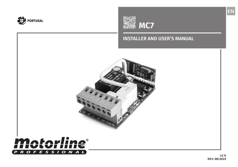
Motorline professional MC70 Instruction Manual

V3.0
REV. 04/2019
MC70(v1.0)
EN
USER/INSTALLER MANUAL
A B
ENEN
2B
3A
5A
5B
6B
8B
4
3B
STANDARDS TO FOLLOW
CONNECTION TO A WALL SWITCH WITH 2 KEYS
TECHNICAL CHARACTERISTICS
PRE-PROGRAMMING INFORMATION
PROGRAMMING
CONTROL BOARD'S RESET
SEVERAL MC70 CONTROL BOARD CONNECTIONS - MASTER FUNCTION
CONNECTION TO A WALL SWITCH WITH 1 KEY
. SAFETY INSTRUCTIONS
. CONNECTIONS SCHEME
. THE CONTROL BOARD
. PROGRAMMING
. CONTENT . SAFETY INSTRUCTIONS
INDEX
• It is important for your safety that these instructions are followed.
• Keep these instructions in a safe place for future reference.
• The ELECTROCELOS S.A. is not responsible for the improper use of the product, or other use than that for which it was
designed.
• The ELECTROCELOS S.A. is not responsible if safety standards were not taken into account when installing the
equipment, or for any deformation that may occur.
• The ELECTROCELOS S.A. is not responsible for insecurity and malfunction of the product when used with components
that were not sold by the them.
• This product was designed and manufactured strictly for the use indicated in this manual.
• This control board is not appropriate for inflammable or explosive environments.
• Any other use not expressly indicated may damage the product and/or can cause physical and property damages, and
will void the warranty.
• Do not make any changes to the automation components and/or their accessories.
• Control board for indoor use with 110V/230V connection.
• Keep remote controls away from children, to prevent the automated system from being activated involuntarily.
• The customer shall not, under any circumstances, attempt to repair or tune the automatism. Must call qualified
technician only.
• The installer must have certified professional knowledge at the level of mechanical assemblies in doors and gates
and control board programmation. He should also be able to perform electrical connections in compliance with all
applicable regulations.
• The installer should inform the customer how to handle the product in an emergency and provide him the manual.
This product is certified in accordance with European Community (EC) safety standards.
This product complies with Directive 2011/65 / EU of the European Parliament and of the Council,
of 8 June 2011, on the restriction of the use of certain hazardous substances in electrical and
electronic equipment.
(Applicable in countries with recycling systems).
This marking on the product or literature indicates that the product and electronic accessories
(eg. Charger, USB cable, electronic material, controls, etc.) should not be disposed of as other
household waste at the end of its useful life. To avoid possible harm to the environment or human
health resulting from the uncontrolled disposal of waste, separate these items from other types of
waste and recycle them responsibly to promote the sustainable reuse of material resources.Home
users should contact the dealer where they purchased this product or the Environment Agency for
details on where and how they can take these items for environmentally safe recycling. Business
users should contact their vendor and check the terms and conditions of the purchase agreement.
This product and its electronic accessories should not be mixed with other commercial waste.
This marking indicates that the product and electronic accessories (eg. charger, USB cable, electronic
material, controls, etc.) are susceptible to electric shock by direct or indirect contact with electricity. Be
cautious when handling the product and observe all safety procedures in this manual.
ATTENTION:
A B
COMAB FCH F N
MOTOR AB ABFCH FCH
PULL230V MASTER
1 2 3 4 5 6 7 8 9 10
1 2 3 4 5 6 7 8 9 10 1 2 3 4 5 6 7 8 9 10
COMAB FCH F N
MOTOR AB ABFCH FCH
PULL230V MASTER
1 2 3 4 5 6 7 8 9 10
ENEN
. CONNECTIONS SCHEME
CONNECTION TO A WALL SWITCH WITH  KEYS CONNECTION TO A WALL SWITCH WITH  KEY
Motor Motor
OPEN
OPEN
OPEN
OPEN
OPEN ALL
OPEN ALL
CLOSE ALL
CLOSE ALL
COM
COM
COM
COM
CLOSE
CLOSE
CLOSE
CLOSE
"MASTER"
WALL SWITCH
 KEYS
WALL SWITCH  KEYS
WALL SWITCH
"MASTER"
WALL SWITCH
VV
All wall switches (local or master) are pressure buttons. All wall switches (local or master) are pressure buttons.
A
1 2 3 4 5 6 7 8 9 10 1 2 3 4 5 6 7 8 9 10
COMAB FCH F N
MOTOR AB ABFCH FCH
PULL230V MASTER
1 2 3 4 5 6 7 8 9 10
1 2 3 4 5 6 7 8 9 10
COMAB FCH F N
MOTOR AB ABFCH FCH
PULL230V MASTER
1 2 3 4 5 6 7 8 9 10
COMAB FCH F N
MOTOR AB ABFCH FCH
PULL230V MASTER
1 2 3 4 5 6 7 8 9 10
EN
230V
V 230V
MC - Nº MC - Nº
OPEN
OPEN
OPEN
OPEN
OPEN
OPEN
OPEN ALL
OPEN ALL
OPEN ALL
CLOSE ALL
CLOSE ALL
CLOSE ALL
COM
COM
COM
COM
COM
COM
CLOSE
CLOSE
CLOSE
CLOSE
CLOSE
CLOSE
WALL SWITCH Nº WALL SWITCH Nº WALL SWITCH Nº
"OPEN"
KEY
opening line (master)
closing line (master)
common line (master) common line (master)
closing line (master)
opening line (master)
"CLOSE"
KEY
"MASTER" WALL SWITCH
MOTOR
Nº MOTOR
Nº MOTOR
Nº
OTHER MC70
MC - Nº
. CONNECTIONS SCHEME
SEVERAL MC CONTROL BOARD CONNECTIONS  MASTER FUNCTION
The MC70 control board MASTER function allows to connect and control several MC70 control boards in the same wall switch (MASTER switch). In this way, whenever a Master switch button is
pressed, all the interconnected control boards send a impulse to the motors to start the maneuver at the same time.
A B
MXSP MXSSP MX///
FALK MXSP
23mm
55mm
44mm
51mm
ENEN
. THE CONTROL BOARD . PROGRAMMING
TECHNICAL CHARACTERISTICS PRE-PROGRAMMING INFORMATION
This control board was developed to control TUB/
Rolling motors. Its small size allows it to be installed
in junction boxes, existents behind electrical switches
(push buttons). It has 2 inputs for pushbuttons
with 1 or 2 keys, one for local control and another
for centralized control, liking several MC70 control
boards on the same wall switch (Master switch).
The control board allows to be controled with
commands through 1 or 3 keys. All programming is
done at a distance, being only necessary acess to
a power supply or a wall switch to program the first
transmitter.
• Power Supply 230V AC 50-60Hz
• Motor's output AC230V; 750W Máx
• Radio Receiver incorporated 433,92 MHz
• Working temperature -20ºC to 70ºC
• Nº of channels 15
• Code type Rolling Code
• Protection grade IP44
• Fixed maximum working time per maneuver 2min
• Dimension of box with control board 56x44x23mm
• Box material ABS
• CHARACTERISTICS BOARD
• CONNECTOR'S DESCRIPTION
CN1
01 • Motor output -Opening
02 • Motor output - Common
03 • Motor output - Closing
04 • 230V power supply (phase)
05 • 230V power supply (neutral)
06 • Wall switch connection - OPENING (NA)
07 • Wall switch connection - COMMON
08 • Wall switch connection - CLOSING (NA)
09 • Wall switch connection - MASTER - OPENING (NA)
10 • Wall switch connection - MASTER - CLOSING (NA)
Attention: The MASTER switch connects the common wire in the 07 connector
The control board allows the programming of two operating modes in transmitters: 1 key or
3 keys.
To know the keys OPEN, STOP and CLOSE of the various transmitters, check the following
schemes:
• TRANSMITTER PROGRAMMING TYPE
OPERATING MODE PERFORMANCE
1 KEY The programmed transmitter will only work with the OPEN key.
This button will send all orders to the control board.
Example: Open - Stop - Close - Stop -Open (...)
3 KEYS The programmed transmitter will work with the buttons: OPEN |
CLOSE | STOP. Each button will send a different order to the board.
OPEN
STOP
OPEN
CLOSE
STOP
CLOSE
ND
OPEN
STOP
CLOSE
ND
OPEN
STOP
CLOSE
ND
OPEN
STOP
CLOSE
ND
A B
5x
3x
5x 2x
2x
5x
5x8x 2x
ENEN
PROGRAMMING
The center allows the connection of pressure switches with one or two keys. To start a
maneuver, just do a simple 1 second pulse at the desired key.
2 KEYS SWITCH
It has two buttons, one for opening and one for closing.
During opening or closing maneuver, a click on the contrary key
to the motor movement will stop this maneuver.
1 KEY SWITCH
It has only one button for opening and closing.
Clicking on the button for opening/closing will stop the motor
movement.
• WALL SWITCHES
OPEN
/STOP
CLOSE
/STOP
OPEN
/STOP
/CLOSE
This control board only allows programming MOTORLINE rolling code transmitters by a
maximum of 15 transmitters. When programming the 16th transmitter, the control board
emits 4 beeps to signal that the memory is full.
It is possible to program the first transmitter through the control board power supply or via
a push button. When you have an already programmed transmitter, you can use it to open
the memory of the control board at distance and program new commands.
Programming new transmitter (3 keys):
• TRANSMITTER PROGRAMMING
01 • Continuously press
the OPEN key of the
transmitter you want to
program.
01 • Continuously press
the OPEN key of the
transmitter you want to
program.
02 • Connect the control
board to a 230 power
supply.
02 • Connect the control
board to a 230 power
supply.
03 • Hold the OPEN key
for 10 sec, during which
the control board emits
5 slowly beeps.
03 • Hold the OPEN key
for 10 sec, during which
the control board emits
5 slowly beeps.
04 • After 10 sec, the
control unit emits 2
quick beeps confirming
confirming the program
success.
04 • After 10 sec, the
control unit emits 2
quick beeps.
Do not release the
transmitter key!
. PROGRAMMING . PROGRAMMING
PRE-PROGRAMMING INFORMATION PROGRAMMING
Programming new transmitter (1 key):
05 • Hold the OPEN key
for 10 sec, during which
the control board emits
3 slowly beeps.
06 • After the total 20
sec (10 + 10), the central
emits 5 quick beeps
confirming the program
success.
Programming new 3 keys transmitter through another already programmed (3 keys):
03 • Continuously
press the OPEN key
of the transmitter
you want to
program.
01 • Continuously
press the OPEN
key of an already
programmed
transmitter, for
15sec.
02 • After 15 sec,
the control board
emits 8 quick
beeps. Release the
key of the already
programmed
transmitter.
04 • Hold the
OPEN key for 10
sec, during which
the control board
emits 5 slowly
beeps.
05 • After 10 sec,
the control unit
emits 2 quick
beeps confirming
the program
success.
A B
3x
5x8x 2x
5x8x 2x
5x8x 2x
3x
5x8x 2x
5x 5x
ENEN
. PROGRAMMING. PROGRAMMING
PROGRAMMINGPROGRAMMING
Programming new transmitter through another already programmed (3 keys):
06 • Hold the OPEN
key for more 10
sec, during which
the control board
emits 3 slowly
beeps.
06 • Hold the OPEN
key for more 10
sec, during which
the control board
emits 3 slowly
beeps.
07 • After the total
20 sec (10 + 10),
the central emits
5 quick beeps
confirming the
program success.
07 • After the total
20 sec (10 + 10),
the central emits
5 quick beeps
confirming the
program success.
Programming new transmitter (3keys) through a 2 buttons wall switch:
01 • Continuously
press the OPEN
and CLOSE keys of
a wall switch, for
15sec.
01 • Continuously
press the OPEN
and CLOSE keys of
a wall switch, for
15sec.
02 • After 15 sec,
the control board
emits 8 quick
beeps. Release
wall switch keys.
02 • After 15 sec,
the control board
emits 8 quick
beeps. Release
wall switch keys.
Programming new transmitter (1key) through a 2 buttons wall switch:
Programming new transmitter (3keys) through a 1 button wall switch:
01 • Continuously
press the wall
switch button, for
15sec.
02 • After 15 sec,
the control board
emits 8 quick
beeps. Release
wall switch key.
03 • Continuously
press the OPEN key
of the transmitter
you want to
program.
03 • Continuously
press the OPEN key
of the transmitter
you want to
program.
01 • Continuously
press the OPEN
key of an already
programmed
transmitter, for
15sec.
02 • After 15 sec,
the control board
emits 8 quick
beeps. Release the
key of the already
programmed
transmitter.
04 • Hold the
OPEN key for 10
sec, during which
the control board
emits 5 slowly
beeps.
04 • Hold the
OPEN key for 10
sec, during which
the control board
emits 5 slowly
beeps.
05 • After 10 sec,
the control unit
emits 2 quick
beeps.
Do not release the
transmitter key!
05 • After 10 sec,
the control unit
emits 2 quick
beeps.
Do not release the
transmitter key!
03 • Continuously
press the OPEN key
of the transmitter
you want to
program.
03 • Continuously
press the OPEN key
of the transmitter
you want to
program.
04 • Hold the
OPEN key for 10
sec, during which
the control board
emits 5 slowly
beeps.
04 • Hold the
OPEN key for 10
sec, during which
the control board
emits 5 slowly
beeps.
05 • After 10 sec,
the control unit
emits 2 quick
beeps confirming
confirming the
program success.
05 • After 10 sec,
the control unit
emits 2 quick
beeps confirming
confirming the
program success.
A B
3x
5x8x 2x
5x
5x 2x 5x 2x
5x 2x
5x 2x
ENEN
01 • Continuously
press the wall
switch button, for
15sec.
02 • After 15 sec,
the control board
emits 8 quick
beeps. Release
wall switch key.
Programming new transmitter (1key) through a 1 button wall switch:
Change motor's direction:
. PROGRAMMING. PROGRAMMING
PROGRAMMINGPROGRAMMING
Delete all transmitters through an already programmed transmitter:
Delete all transmitters through a 2 buttons wall switch:
01 • Continuously press
the OPEN and CLOSE
keys of a wall switch.
02 • Connect the control
board to a 230 power
supply.
Delete all transmitters through a 1 button wall switch:
01 • Continuously press
the wall switch button. 02 • Connect the control
board to a 230 power
supply.
03 • Continuously
press the OPEN key
of the transmitter
you want to
program.
04 • Hold the
OPEN key for 10
sec, during which
the control board
emits 5 slowly
beeps.
05 • After 10 sec,
the control unit
emits 2 quick
beeps.
Do not release the
transmitter key!
06 • Hold the OPEN
key for more 10
sec, during which
the control board
emits 3 slowly
beeps.
07 • After the total
20 sec (10 + 10),
the central emits
5 quick beeps
confirming the
program success.
01 • Continuously press
the CLOSE key of an
already programmed
transmitter.
01 • Continuously press
the OPEN and CLOSE
keys of an already
programmed transmitter.
02 • Connect the control
board to a 230 power
supply.
02 • Connect the control
board to a 230 power
supply.
03 • Hold the CLOSE key
for 10 sec, during which
the control board emits
5 slowly beeps.
03 • Hold the button for
10 sec, during which the
control board emits 5
slowly beeps.
03 • Hold the OPEN and
CLOSE keys for 10 sec,
during which the control
board emits 5 slowly
beeps.
03 • Hold the OPEN and
CLOSE keys for 10 sec,
during which the control
board emits 5 slowly
beeps.
04 • After 10 sec, the
control unit emits 2
quick beeps confirming
confirming the program
success.
04 • After 10 sec, the
control unit emits 2
quick beeps confirming
confirming the program
success.
04 • After 10 sec, the
control unit emits 2
quick beeps confirming
confirming the program
success.
04 • After 10 sec, the
control unit emits 2
quick beeps confirming
confirming the program
success.

Other Motorline professional Control Unit manuals

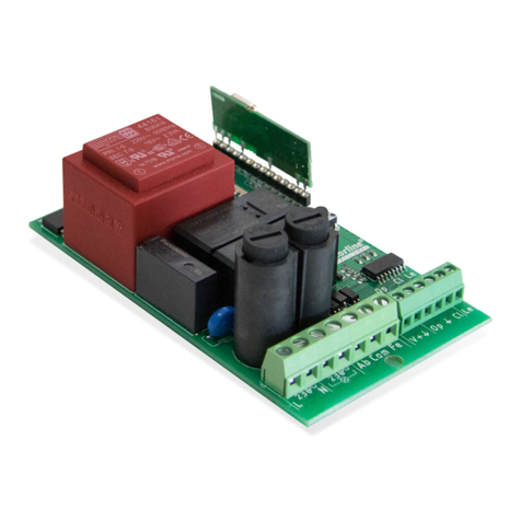
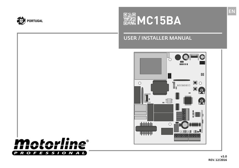
Motorline professional MC15BA Instruction Manual

Motorline professional

Motorline professional MC15BA Instruction Manual

Motorline professional MC60 Use and care manual

Motorline professional

Motorline professional MC60 Use and care manual

Motorline professional MC61PL Operation and installation manual

Motorline professional

Motorline professional MC61PL Operation and installation manual

Motorline professional MC41SP Instruction Manual

Motorline professional

Motorline professional MC41SP Instruction Manual

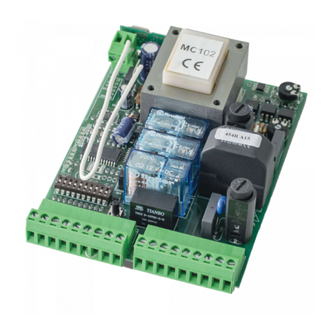
Motorline professional MC102 Instruction Manual

Motorline professional

Motorline professional MC102 Instruction Manual

Motorline professional MCONNECT SHUTTER Use and care manual

Motorline professional

Motorline professional MCONNECT SHUTTER Use and care manual

Motorline professional MC7 Operation and installation manual

Motorline professional

Motorline professional MC7 Operation and installation manual

Motorline professional MC61BR Operation and installation manual

Motorline professional

Motorline professional MC61BR Operation and installation manual

Motorline professional MC4 EVO User manual

Motorline professional

Motorline professional MC4 EVO User manual

Motorline professional MC112N Use and care manual

Motorline professional

Motorline professional MC112N Use and care manual

Motorline professional MC112PR User manual

Motorline professional

Motorline professional MC112PR User manual

Motorline professional MC70 EVO Instruction Manual
Motorline professional

Motorline professional MC70 EVO Instruction Manual

Motorline professional MC61SE Operation and installation manual

Motorline professional

Motorline professional MC61SE Operation and installation manual

Motorline professional MC75 Use and care manual

Motorline professional

Motorline professional MC75 Use and care manual

Motorline professional MC61PL Instruction Manual
Motorline professional

Motorline professional MC61PL Instruction Manual

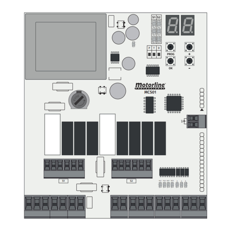
Motorline professional MCS01 Instruction Manual

Motorline professional

Motorline professional MCS01 Instruction Manual

Popular Control Unit manuals by other brands

Johnson Controls EM-3000 Series quick start guide

Johnson Controls

Johnson Controls EM-3000 Series quick start guide

National Instruments NI 9211 Getting started guide

National Instruments

National Instruments NI 9211 Getting started guide

CALEFFI TankMixer 520 Series quick start guide

CALEFFI

CALEFFI TankMixer 520 Series quick start guide

EMKO TRANS-AMF user manual

EMKO

EMKO TRANS-AMF user manual

Metso Jamesbury 4000 B Installation maintenance and operating instructions

Metso

Metso Jamesbury 4000 B Installation maintenance and operating instructions

Comunello Automation CU-230V-1M Installation and user manual

Comunello Automation

Comunello Automation CU-230V-1M Installation and user manual

RTimes X509 product manual

RTimes

RTimes X509 product manual

Viking VXD Technical data

Viking

Viking VXD Technical data

CDVI TPV installation manual

CDVI

CDVI TPV installation manual

flamco Prescor SB Installation and operating instructions

flamco

flamco Prescor SB Installation and operating instructions

Viessmann Dekamatik-HK1 installation instructions

Viessmann

Viessmann Dekamatik-HK1 installation instructions

Frequency Central Infinitely Maybe Build documentation

Frequency Central

Frequency Central Infinitely Maybe Build documentation

Burkert 8697 operating instructions

Burkert

Burkert 8697 operating instructions

Task Force Tips Twister Instructions for installation, safe operation and maintenance

Task Force Tips

Task Force Tips Twister Instructions for installation, safe operation and maintenance

FrSky TANDEM X20 Pro instruction manual

FrSky

FrSky TANDEM X20 Pro instruction manual

Roger EDGE1 Series Instruction and warnings for the installer

Roger

Roger EDGE1 Series Instruction and warnings for the installer

Kidde GSA-CC1 Installation sheet

Kidde

Kidde GSA-CC1 Installation sheet

Wolf RK-2 Wiring diagram, Installation and short operating instructions

Wolf

Wolf RK-2 Wiring diagram, Installation and short operating instructions

manuals.online logo
manuals.online logoBrands
  • About & Mission
  • Contact us
  • Privacy Policy
  • Terms and Conditions

Copyright 2025 Manuals.Online. All Rights Reserved.