Windsor L175 User manual

Contents:
1
Warnings
-
ProductDescription
2
4
Wiring Diagrams
5
Motor, Frame, Driver Assembly
6
Cover Assembly
7
Handle Assembly
9
Trouble Shooting
10
Warranty
Operation
/
Maintenance
/
Service
Record model and serial number located on
datalabel. Refertothesenumberswhencalling
Windsor dealer for partsor service.
MODEL
:
SERIAL
NO.
:
PURCHASE
DATE
:
WARNING
OF
A
POTENTIAL INJURY:
This productcontains moving parts. To
reducethe risk of injury unplugthe
machine beforeservicing.
Whenever repairsaremadeensureelectrical
connections are correct andwiring matches
APPROPRIATE
diagram before plugging
machine into an electrical outlet.
CAUTION:
1
.)
Seethe Owner’s Guidefor
completeoperating instructions.
2.)
Maintenance
and
repairsmustonly
bedone byqualified personnel.
3.)
Usingnon
-
Windsorpartsto repair
this machinewillvoidthewarranty.
0
80110
USA
303-762-1800*FAX3
98116
Rev.1
512/94

INSPECTION
OPERATION
Please carefullyunpack and inspectyour machine
for shipping damage. Eachunit is operatedand thor
-
oughlyinspectedbeforeshipment,andany damage is
the responsibilityof the delivering carrierwho should
be notifiedimmediately.
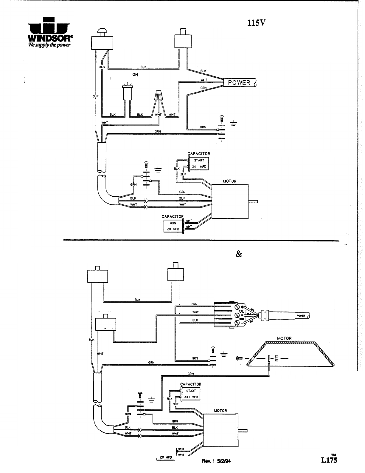
ELECTRICAL
Thisrotary polisheris designedto operateon astandard
15
amp,
115
volt,
60
hz,
AC
householdcurtent. Checkthatthe
voltageshown onthe serial numberplateissuitablefor the
supplyavailable.Voltagesbelow
105
voltsor above
125
volts
couldcausedamage to the motor.
NOTE: 230/250volt
50
hz
models
areavailable.
,
GROUNDING INSTRUCTIONS
Thisappliancemustbegrounded.
If
itshouldmalfunc
-
tionor breakdown, grounding providesa pathof least
resistancefor electriccurrenttoreducethe riskof elec
-
tric shock. This appliance isequippedwithacord hav
-
inganequipment
-
groundingconductorandgrounding
plug. Theplugmustbeinsertedintoanappropriateout
-
let that is properly installed and grounded in accor
-
dancewith all localcodes and ordinances.
WARN
1
NG
:
Improper connectionof the equipment
-
grounding
conductor can result in
a
risk of electric shock.
Checkwithaqualifiedelectricianor serviceperson
if
you are indoubtas
to
whether the outlet
is
prop
-
erly grounded.
Do
not modify the plug provided
withthe appliance
-
if
itwill notfit the outlet, have
a properoutlet installedby
a
qualifiedelectrician.
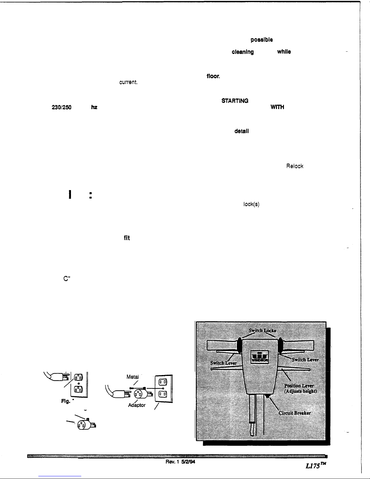
This applianceisfor useon anominal 120
-
voltcircuit,
andhasagroundedplugthat looksliketheplugin
“Fig.
A
below.
A
temporaryadaptorthatlooksliketheadap
-
tor
in
“Fig
.
C“
below
may
beusedtoconnectthis plug
to
a
2
-
pole receptacleas shown in“Fig.
B
below,
if
a
properly groundedoutlet is not available. The tempo
-
rary adaptor should be used only until a properly
groundedoutlet (Fig.
A)
canbe installedby a qualified
electrician. Thegreencoloredrigidear, lug,
or
the like
extendingfromtheadaptormustbeconnectedtoaper
-
manentgroundsuchas aproperlygroundedoutletbox
cover. Wheneverthe adaptor
is
used, it must be held
inplace by a metalscrew.
PROPER GROUNDING CONNECTION
CONNECTION USING
AN
ADAPTOR
GROUNDING
GroundingPin
\\
I
-
Metal
Screw
Grounded
Outlet
Rg.
A
/
Tab
For Groundina
-
Screw GroundedOutlet
Box
ADAPTOR
-
flg.
B
NOTE: Adaptors
are
notallowed InCanada.
‘6
Fig.
C
CAUTION: For indoor
Use
Only.
To
prevent possibledamage to thefloor
when using the Brushoptlon, usewater or other
approvedcleanlng solutionwhile operating.
When using the padoptloln, always keep
the machine movingwhen In contactwith the
floor.
WARNING:
HIGHSTARTINQ
TORQUE.
HOLD MACHINE FIRMLY
WITH
BOTH
HANDS.
1
.)
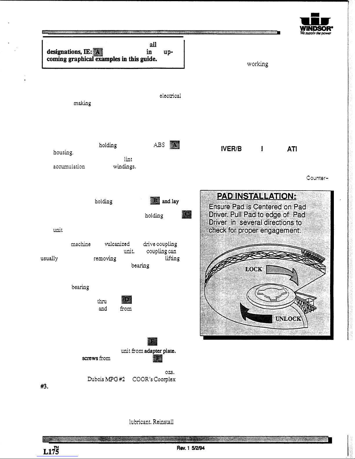
Ensurethatthepaddriver
or
brushisinstalledcorrect
-
ly and ingood shape. Installor change pad
if
necessary
(See Page 3
for
detall
of
Installation).
2.)
Plugthe machineintoawall outlet
as
describedinthe
grounding instructions.
3.)
Lowerthehandle
by
unlockingtheadjustmenthandle
and movingthe handle into position. Relock the handle
when itis ina comfortableposition.
4.)
Check to be sure the pad driver or brush is installed
beforestarting.
5.)
Withthe switch lock@)rotatedforward, squeeze
one
of theswitchlevers,turningthemachineon. (Theselevers
can beoperatedindependently
of
each other)
6.)
To
stop the machine, release the switch lever
and
switchlock.
NOTE
The machineisequippedwitha circuitbreaker
to
protectthe motor inthe event
an
overload condition
occurs. The circuitbreaker islocated
at
thebottom
of
the
switch housing. Push the reset buttonto restart the ma
-
chine.
If
thebreakertripsagain, correctthecause
of
over
-
loadingbeforeproceeding.
7.)
Do
notletmachinerestonpad. Whenfinishedwiththe
machinefor the day returnhandletothe storage position.
Besureto leavemachineina
safe
placewherethere isno
risk
of
beingtippedover.
CONTROLS
Page
2
R0v.l
y2/94
L175”

..
.
.
I
1
NOTE:
In
the
following
instructions
all
letter
will
be
shown
in
the
up-
DAILY
MAINTENANCE:
(At
the
end
of
each
working
day):
1.
Inspect power cord for wear.
To
prevent
electrical
shock replace cordswith frayed or cracked insulation
MAINTENANCEINSTRUCTIONSFOR THE
L175
SERIES
OF FLOOR SCRUBBERS
immediately.
Place machine
in
the storageposition.
Check pad condition. Change
if
soiled or torn,
2.
3.
WARNING:
Remove machine power cordfromelectrical
sourcebeforemaking any adjustmentsorrepairs to the
machine.
Only qualifiedmaintenancepersonnel are
to
PADS:
performrepairs.
MOTOR
Only
standard
1/2
inch thick
pads
suitablefor low
speed
burnishing
are recommended.
PAD
D
R
IV
ER/B
R
US
H
I
NSTA
LL
AT1
0
N
:
1.
2.
1.
2.
Remove
(4)
screwsholding motor coverto
ABS
housing.
Use compressed
air
toremove lint
and
dust
accumulationfrommotorwindings.
Lay
machine back on
the
ground, exposing
the
underside.
Place pad driver or
brush
on
the
motor lug and rotate
clockwise
until
engaged.
To
remove,
turn
Counter-
MOTOR
-
GEAR UNITASSEMBLY
1.
2.
Remove
(4)
bolts holdinghandle bracket
aside. Lift
off
plasticmotor shroud.
Tip machineback
and
remove
(4)
boltsholding brush
coverand gear unit to
chassis.
Lift
outmotor and gear
unit assembly.
NOTE:
Themachinehas a vulcanizedsteeldrivecoupling
locatedbetween
the
motor
and
gear
unit.
The coupling
can
usually be replaced by removing the motor coverand lifting
outthe armature.
If
the
lower
armature
bearing
remains
in
gearunit adapterplate, it
will
have
to
be
removedfrom the
gear
box
to
access the bearing
for
removal.
3.
Remove
(4)
motor
thru
bolts and
lift
off
motor
cover. Remove armature
and
fieldfromgearunit adapter
plate.
GEAR UNIT
1.
2.
3.
NOTE:
The
maximum
capacity
of
the
gear
unit
is
10
ozs.
Use
gearbox greaseDubois
MPG
#2
orCOOR’s Coorplex
#3.
Remove
(6)
screws
from
adapterplate.
Use
pry bars to seperategearunit fiom
Remove
(6)
saws
fnnn
gearunit cover.
Removecover. Repair
as
needed.
WHEELS
1.
Removewheels every
2
to
3
moths. Clean axle an
apply
a
small
amount
of
siliconelubricant. Reinstall
wheels.
clockwise.
NOTES:
L1%
Rev.1
5/2/94
3

4
SWITCH
fi
I
CIRCUIT BREAKER
-
POWER
ON
INDICATOR LAMP
I
115V
WIRING DIAGRAM
.
$APACITOR
I
SWITCH CIRCUIT BREAKER
-
230V
&
250V
WIRING
DIAGRAM
11
SWITCH
MO.TOR
COVER
GUN
w
b
CAPACITOR
20
m
Rev.1
512/94
Ll%

Aun.
1
2
3
4
5
6
7
8A
8B
9A
9B
1OA
1OB
11A
11B
12
13
14
15
16
17
18
19
20
21
22
23
z+t
24
L175
25
34171
70335
87016
87025
70329
87067
70083
14608
14561
2007
1
20070
73306
73304
02108
02107
02106
70043
36103
36102
09040
09042
36100
36101
09038
27353
09043
2735
1
27352
73392
Frame
Screw, 10
-
32
x
1/2
PHTF
26
Washer,
#lo
Star
27
Washer, 114
Star
28
screw, 1/4
-
20
x
314
PHTF
29A
Washer, 5/16
Star
29B
screw, 5/16
-
18
x
1
HHMS
30A
._B~mp~r,
L175
-
17 30B
Bump. L175-20
31
clnmp, L175-17 32
Clamp, L175-20 33
Shroud.
L175
-
17 34
Shroud,
L175-20 35
Pad
Driver, L175-17 36
Pad
DI~vc~,
L175
-
20 37
Plate,
Clutch
L175
38
Screw,
10
-
32
x
5/8
FHMS
39
Gear
Unit
Assembly
40
Gear,
CoverDrive(131T) 41A
Bearing, Drive Cover 41B
Bearing,
Motor
Lower 42A
Gear.
met
(58-0
42B
Gear,
Pinion
(13T)
44
Bearing,
Motor
Lower 45
cage.
3
Planet
Gear
46
Bearing,
Rotating
Cover 47
Cover, Rotating
48
coupling 49A
Spacer.Bhg
Rev.
1
5/2/94
49B
70353
3609
7035
53179
53180
73391
73393
87013
70354
31060
62262
70323
87105
87106
72064
70234
09039
72071
72065
67199
67200
27358
14639
7035
1
27357
14624
53168
53168
Screw, 10
-
32
x
314
SHCS
Gear
End
Shield
Screw, 10
-
32
x
1.25
SHCS
Motor, 115Vw/o
Gearbox
Motor, 220-24OV w/o Gearbox
Stator
Asm.
115V
stator
krm,
220-25ov
Washer, 114
ID
x
5/8
OD
Screw. 1/4
-
28 x 7.50 HHCS
End
Shield
Plate,
Motor
Access
Screw. 10
-
32
x
114
PHTP
Washer, 1.56
OD
Washer, Thrust
1
SO
OD
Switch,
Staionary
Screw, 10
-
32
x
3B
PHST
Bearing,
Upper
Motor
Switch,
Centrifugal
115V
Switch,
Centrifugal
220-25OV
Rotor
Asm,
11N
(w/SW &BRG)
Rotor
Asm,
220-25OV (w/SW
&
BRG)
Capacitor,240V
6OHz
20MFD
run
Bracket,Capacitor
Screw, 10
-
32
x
3/8
HHTF
w/star
Capacitor, llOV
6OHz
341
MFD
start
Bracket,Capacitor
Motor, ll5V
1.5Hp
wKieprbox
Motor.
240V
1SP
wKitarbox
5

KEY
1
2A
2B
6
7
8
9
10
11
12
13
14
15A
15B
16
17
18
19
20A
20B
22
6
21
KEY
23
24
25
26
27
28
29
30
31
32
33
34
35
36
37
38
39
40A
4OB
41
42
43A
43B
PART
NO.
57040
27331
27355
73195
70347
70083
87083
70071
14603
14532
70177
20069
70330
70482
51114
27340
73307
87086
88445
88553
87067
DESCRIPTION
Nut,
1/2
NPT
Conduit
cover, 115v
Cover, 220
-
25OV
Shaib
Relief.
1/2
NFT
Screw, 5/16
-
18
x
1
HHMS
Washer, 5/16 Split
Lock
Screw, 4.40
x
1/2
PHST
Bumper, L175 Handle Bracket
Bracket,Handle Pivot
Screw, 10
-
32
x
1/2
FHMS
Clamp,
Cord
SetScrew, 5/16
-
18
x
1/2
Set
Screw,
5/16
-
18
x
314 (L175)
Handle Position
Lock
Handle
Lock
Cable
Spring,
Polisher
Lock
Washer, M10
x
30
Wire
Asm,
115VL175 Handle
Wire
Am.
220
-
25OV L175
Washer. 5/16
Star
Screw, 1/2
-
13
x
3 HHCS
70345 Screw, 5/16
-
18
x
2
SHCS
Rev.,
5/2/94
PART
NO.
66114
3608
1
41143
57118
03055
89064
87008
87025
70020
38153
50401
27338
70086
57028
87018
70187
57104
88557
88808
70162
87010
23169
23167
DESCRIPTION
Pin,
114
x
1.75
Gearm
Housing, Handle Pivot w/Hook
Nut,
1/2
-
13UNC
Nylock
Axle
Wheel
Washer, 1/4
ID
x
1.25
OD
Washer, 1/4
Star
screw. 1/4
-
20
x
1/2
HHMS
Handle
Label,
175
Lightning
Motor Cover
Screw, 10
-
24
x
1/2
PHMS
Nut,
10
-
24
li~m
Washer, #lo
Flat
Nut,
10
-
32Hex w/
Star
washer
Wire. ll5VGround
Wire, 220-25OV Ground
Screw, 10
-
32
x
3/8PHMS
Washer, .578
ID
x
1.060
DX
.63
Cord Set,
15MM
Euro
x
50'Blk
Screw, 10
-
24
x
1/2
PHST
-
F
-
cord set, 1413
std
x
50' nw.

208
*Use
for
both
sides
(2)
7
230V
250V
Switch
and
Terminal
Block
Asm

KEY
1A
1B
2
3
4
5
6
7A
7B
7c
7d
8
9
10
11
12
13
14
15
16
17
18
19
20A
20B
21
22
23
24
25
26
27A
27B
28
29
30
31
32
33
34
35
8
PART
#
14700
14312
27558
50649
57024
70384
57006
41234
41246
41244
41243
51188
66187
76ll2
36139
51192
51191
73571
70242
70451
70455
73400
73402
72123
72119
70351
20054
70335
87016
57003
99627
23167
23169
78288
73572
._
62251
62344
78270
66199
62399
51187
DESCRIPTION
Breaker
15A25OVAC
50VDC
Breaker,
7A
Circuit
Collar, CitBreaker
Label, CircuitBreaker
Nut,
3/8
-
27
Panel
Nut,
1/4
-
20
Hex Pltd
Housing, POLHandle (Logo)
Housing, POLHandle Rear Mach’d
Housing, POLHandle Top
Housing, POLHandle
Bottom
Lever, HeightPolisherHandle
pin,
POLHandle
Terminal
Block, 3
position
Grip, Handle
Lock,
SwitchLt. POLHandle
Lock,
Switch Rt. POLHandle
Spring, Handle
Lock
Scr,
4
-
40
x
1/4
PHMS Pltd.
SC~,
1/4
-
20
x
1/2
PHTRPltd.
Scr,
1/4
-
20
x
1.62
SHCSPltd
Scr,
#6-32
x
1.00
PPmPltd.
Spacer,
UL
Switch
Spacer,
Adj.
Handle
Switch, SnapPOL Handle
230V
Clamp,
318
Nylon
WCSA
Washer,
#10
Lock
Ext
Star
SS
Nut, Yellow
Wire
ElectricTape,
3/4
w/UL-CSA
Cord
Set,
14/3
Std
x
50’
Yellow
Cord Set,
1.5mm
Euro
x
50’
Blk
Tube,
PolisherHandle Merit
Spring,SwitchHandle
Plate, Handle Lever
Plate, LeverPlug
Tube,
Handle Polisher
Pin, PolisherHandle
Plate,Retainer
230V
Lever, SwitchPolisherhandle
Switch,
25A
SPST
125-25OV
Snap
Scr,
10
-
32
x
3/8
HHTR
w/SW
Scr,
10
-
32
x
1/2
PHTR Gm/Gmd
QTY.
1
1
1
1
1
4
2
2
1
1
1
1
3
1
2
1
1
2
2
2
2
1
1
1
2
1
1
1
1
1
1
1
1
1
1
1
1
1
2
1
1
Rev.
1
5/2/94
NOTES
All
230V
“I”
&
250V ‘?A”
Qty.1
on
230V
”I”
machines.
Used
on
230V
”I”
machines
only.
Used
on
250V
“LA”
machines
Used
on
250V
“IA”
machines
All 230V
“I”
&
250V
“IA”
Used
on
ll5V
machinesonly.
A11
ll5V
machines.
All
23OV
”I”
&
250V
“IA”
All ll5V
machines.
All
ll5V
machines.
All ll5V
machines.
All 230V
”I”
&
250V “IA”
All 230V
”I”
._
1M
1175

TROUBLE
SHOOTING
CHART
:
PROBLEM POSSIBLE
CAUSE
SOLUTION
No
power
to
Deadelectrical circuit Check building circuit
machine
breakeror fuse
box.
Power switch failure
Faulty circuit breaker Replace.
Faulty power cord Replace.
Test switch for continuity and replace
if
necessary.
Electrical
shock
Equipmentnot
grounding Followgrounding instructionsexactly.
Receptacle not
grounded Havean electricianinspectbuilding’s
wiring.
Internalwiring
problem Ensurethat the machineswiring
matchesthe appropriate wiring diagram.
Replaceany wires or componentswhich
are short circuiting.
Circuit breaker
Faulty circuit breaker Test circuit breakerfor continuity.
tripping
Replacecircuit breaker
if
necessary.
Mechanicalproblem Higher amp draws indicatea mechanical
problem, find the parts which are not
moving
as
freely as they should, andrepair
or replace.
NOTES:
TM
LJ75
Rev.1
5/2/94
9
Table of contents
Other Windsor Sander manuals