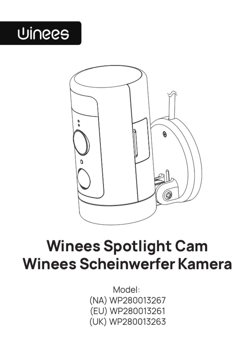
winees F3 User manual

Quick Start Guide
F3 & F2 & F2 Pro

PRODUCT OVERVIEW 03
INSTALLATION 09
CAUTIONS 39
IN THE BOX
01
APP SETUP
05
LIGHT INDICATIONS
38
NEED HELP?
42

EN
Floodlight Camera Quick Start Guide Screws Pack B Screws Pack C Screws Pack D
Screws Pack A3Screws Pack A2Screws Pack A1
Installation Hook
Rubber Stopper
Power Cord Wire NutsMetal Bracket
Quick Start Guide
F3 & F2 & F2 Pro
IN THE BOX
1EN 2

EN
3EN 4
PRODUCT OVERVIEW F3 & F2 Pro PRODUCT OVERVIEW F2
1. Floodlight
2. Speaker
3. Microphone
(Dual-mic only the F3)
4. 3D Radar Sensor
(Only the F3)
5. LED Indicator
6. Light Sensor
7. Motion Sensor
9. MicroSD Slot
(SD card not included)
10. Security Screw
12. Rubber Stopper
13. Mount Bracket
1. Floodlight
2. Speaker
3. Microphone
4. LED Indicator
5. Motion Sensor
6. Light Sensor
8. MicroSD Slot
(SD card not included)
9. Security Screw
11. Rubber Stopper
12. Mount Bracket
Note: As the process of adding the device and installation is the same
for both the two-head and three-head models, we will use the
three-lamp model as an example for the subsequent illustrative guide.
1
7
8
9
7
8
9
2
3
66
10
11 10
12
13
5
4
1
2
3
5
4
11
12

APP SETUP
will hear "Welcome, please add the camera in the app"
1. Scan the QR code below
to download the AiDot app.
Or search for“AiDot” in
App Store or Google Play.
EN
5EN 6

model you purchased from the "Surveillance"
category. Follow the instructions on the app.
5. Unscrew the power cord; wire nuts will be used later.
The power cord is not required when mounting
EN
7EN 8
9:41
Surveillance
Camera
F1
M3/M3 Plus
F3
Mini/M1/M2
M2X
L1

INSTALLATION
Burn hazard. Allow the light fixture to cool
before touching it.
Please confirm if you have installed the
junction box. If not, please find a professional
electrician to install the junction box.
To avoid risk of shock, injury or death,
always be cautious when working with
electricity.
Do not connect this light fixture to a
dimmer switch or timer.
Any changes or modifications to this unit
not expressly approved by the party
responsible for compliance could void the
user’s authority to operate the equipment.
fuse. To be safe, please verify that the power
Fire hazard. Keep the lamp heads at least
EN
9EN 10

Before any installation
- Make sure the power supply is 100-240V~0.35A max
50/60Hz power source.
ON
OFF
ON
OFF
ON
OFF
ON
OFF
ON
OFF
ON
OFF
ON
OFF
ON
OFF
ON
OFF
ON
OFF
1
2
3
4
5
6
7
8
9
10
disconnect the wires.
EN
11 EN 12

remove it as well.
3. The junction box and existing electrical wires are
Placement
down or vertically on the wall. Choose the mounting
method that best suits your junction box location.
Upside Down MountWall Mount
EN
13 EN 14

you follow the steps below to mount the camera.
- Recommended mounting height is 2.5 to 3 meters
(8.2 to 9.8 feet) above the ground. Either too high or
motion detector.
10m (32.8feet)
2.5~3m
(8~10feet)
2.5~3m
(8.2~9.8feet)
20°±5°
NOTICE:
- The concaved side of the metal bracket must face outwards.
- The metal bracket needs to be installed horizontally on the ground.
- The wires need to come out from above the metal bracket.
Wall mount
1. Install the new metal bracket to the junction box.
Align the two screw holes and tighten the bracket
using matching screws(Pack A1, A2 or A3).
EN
15 EN 16

wire(yellow or green) to the middle of the metal
bracket.
camera and pull outward to release the mount
1 2
EN
17 EN 18

4. Hang the mount bracket on the metal bracket with
the installation hook.
1. Hold the wires together 2.Twist the wires nut 3-5 times
5. Use wire nuts to connect mount bracket wires to
the rest of the wires from junction box.
- Connect the white wire on the mount bracket to the
white wire(neutral) from the junction box.
- Connect the black wire on the mount bracket to the
black wire(hot) from the junction box.
NOTICE:
If you are in Europe please follow:
- Connect the blue wire on the mount bracket to the blue wire(neutral)
from junction box.
- Connect the brown wire on the mount bracket to the brown wire(hot)
from junction box.
EN
19 EN 20

6. Insert the central screw(Pack B) through the
center of mount bracket and screw it tightly. Use the
rubber stopper to cover the central screw to prevent
the it from rusting.
NOTICE:
- Pull the wire down slightly to make sure the wire nuts secure the cable.
- Never cross connect.
EN
21 EN 22

with the groove of the mount bracket, then push in
camera and mount bracket are combined.
NOTICE:
- Please put the ladder on the side of the equipment for installation
which will be more convenient to operate.
and mount bracket to make sure it's locked.
security screws(Pack C).
EN
23 EN 24

9. After installation is complete, you can adjust the
10. Switch on the main circuit breaker in the house.
the LED indicator lights up solid green.
EN
25 EN 26

1. Install the new metal bracket into the junction box.
Align the two screw holes and tighten the bracket
NOTICE:
-The concave direction of the mount bracket is the direction of your
camera field of view.
-The metal bracket needs to be perpendicular to the concave
direction of the mount bracket.
-The wires need to come out from behind the metal bracket.
Upside down mount
FORWARD
wire(yellow or green) to the metal bracket.
EN
27 EN 28

camera and pull outward to release the mount
bracket from the camera.
21
4. Hang the mount bracket on metal bracket with the
installation hook.
EN
29 EN 30

5. Use wire nuts to connect the mount bracket wires
to the rest of the wires from junction box.
- Connect the white wire on the mount bracket to
the white wire(neutral) from the junction box.
- Connect the black wire on the mount bracket to the
black wire(hot) from the junction box.
NOTICE:
-Never cross connect
If you are in Europe please follow:
- Connect the blue wire on the mount bracket to the blue wire(neutral)
from junction box.
- Connect the brown wire on the mount bracket to the brown wire(hot)
from junction box.
1. Hold the wires together 2.Twist the wires nut 3-5 times
NOTICE:
-Pull the wire down slightly to make sure the wire nuts secure the cable
EN
31 EN 32

6. Insert the central screw(Pack B) through the
center of mount bracket and screw it tightly. Use the
rubber stopper to cover the central screw to prevent
the it from rusting.
NOTICE:
The concave direction of the mount bracket is the direction of your
camera field of view.
camera with the groove of the mount bracket, then
push in until you hear a "click" to make sure the
EN
33 EN 34

NOTICE:
- Please put the ladder on the side of the equipment for installation
which will be more convenient to operate.
camera and mount bracket to make sure it's locked.
security screws(Pack C).
9. After installation is complete, you can adjust the
EN
35 EN 36
This manual suits for next models
2
Table of contents
Other winees Spotlight manuals
Popular Spotlight manuals by other brands

LIVARNO LUX
LIVARNO LUX LED SPOTLIGHT 20W Assembly, operating and safety instructions

LIVARNO LUX
LIVARNO LUX ESL-156 Operation and safety notes

LIVARNO home
LIVARNO home 898-S-2 Operating and safety instructions

LTS
LTS Torpedo 500 LED Installation instruction

SNOWJOE
SNOWJOE SUNJOE 24V-1500FL-LTE-P1 Operator's manual

Ultimate Illumination Laboratories
Ultimate Illumination Laboratories SBS2000H3 manual