manuals.online logo
Brands
  1. Home
  2. •
  3. Brands
  4. •
  5. Winegard
  6. •
  7. Antenna
  8. •
  9. Winegard YA7000C User manual

Winegard YA7000C User manual

Winegard Company • 3000 Kirkwood Street • Burlington, IA 52601-2000
90 DAY LIMITED WARRANTY
Winegard Company warrants this Winegard product against any defects in materials or workmanship within 90 (ninety)
days from date of purchase. No warranty claim will be honored unless at the time the claim is made, you present proof
of purchase to an authorized Winegard dealer (if unknown, please contact Winegard Company, 3000 Kirkwood Street,
Burlington, IA 52601-2000, Telephone 800-288-8094).
Winegard Company (at its option) will either repair or replace the defective product at no charge to you. This warranty covers
parts, but does not cover any costs incurred in removal, shipping or reinstallation of the product. This limited warranty does
not apply if the product is damaged, deteriorates, malfunctions or fails from: misuse, improper installation, abuse, neglect,
accident, tampering, modication of the product as originally manufactured by Winegard, usage not in accordance with
product instructions or acts of nature such as damage caused by wind, lightning, ice or corrosive environments such as
salt spray and acid rain.
The90DayWarranty is provided on the conditionthattheequipmentisproperlydeliveredwithallhandlingandfreight charges
prepaid to your Winegard dealer for return to our factory for repair or replacement. Winegard dealers will arrange for the
replacement or repair and return to you without charge the product which failed due to defective material or workmanship.
WINEGARDCOMPANY WILLNOTASSUMEANYLIABILITIES FORANY OTHER WARRANTIES, EXPRESS OR IMPLIED,
MADE BY ANY OTHER PERSON.
ALL OTHER WARRANTIES WHETHER EXPRESS, IMPLIED OR STATUTORYINCLUDING WARRANTIES OF FITNESS
FORAPARTICULAR PURPOSEAND MERCHANTABILITYARE LIMITED TOTHE 90-DAYPERIOD OF THISWARRANTY.
The foregoing shall be the sole and exclusive remedy of any person, whether in contract, tort or otherwise, and Winegard
shall not be liable for incidental or consequential damage or commercial loss, or from any other loss or damage except
as set forth above.
Some states do not allow limitations on how long an implied warranty lasts, or the exclusion of limitation of incidental or
consequential damages, so the above limitations or exclusions may not apply to you.
This warranty gives you specic legal rights and you may also have other rights which vary from state to state.
Printed in U.S.A. © Winegard Company 2008 Rev4 01/21 2452439
Rev. 2/08
2452439
Rev4 01/21
FREE AT
Finding your favorite TV programming has
never been easier! Using your current
location, the app can help determine
the correct antenna positioning
to avoid obstructions with the
augmented reality (AR) view.
WINEGARD’S
HDTV TOWER FINDER APP
Register your product at
winegard.com/myantenna.
For help, email
[email protected]
LIGHTNING PROTECTION
FOR TV ANTENNA & SET
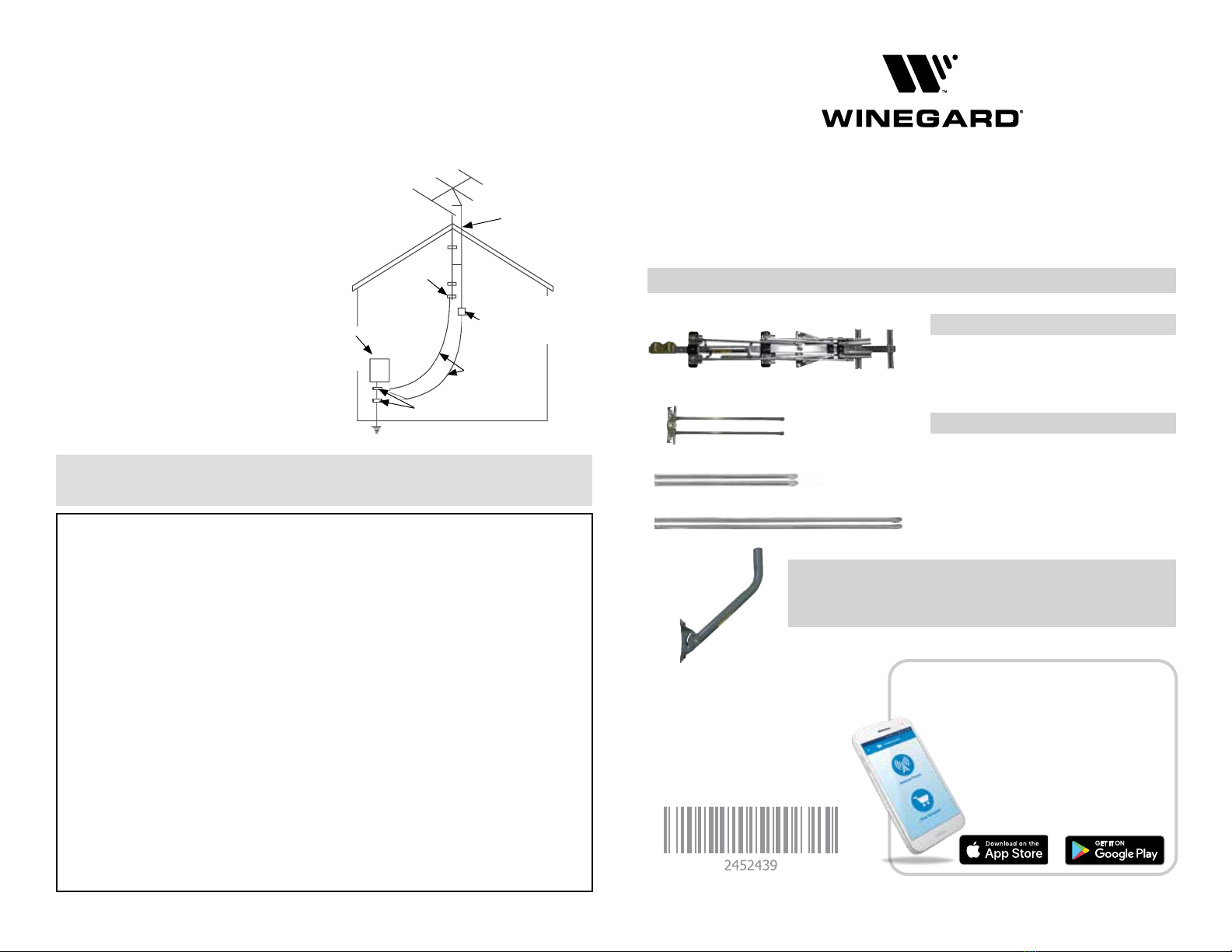
1) Mount the lightning arrestor or 75
ohm coaxial grounding block as close
as possible to where the 75 ohm
coaxial cable downlead enters the
house. See Figure at right.
2) The ground wires for both the mast
and the downlead should be copper
or aluminum wire, number eight or
larger. See at right.
3) The downlead wire from the antenna
to the lightning arrestor and the mast
ground wire should be secured to the
house, spaced from four to six feet
apart. See Figure at right.
WARNING:Installation of this antenna near power
lines is dangerous! For your safety,
follow the installation instructions.
VHF/UHF Models YA7000C and YA7000D
VHF/UHF (HD) Antenna
INSTRUCTION MANUAL
NOTE:
Example of antenna grounding as per
National Electrical Code, ANSI/NFPA 70
Antenna Lead
In Wire
Ground
Clamp
Electric
Service
Equipment
Antenna
Discharge Unit
(NEC Section 810-20)
Power Service Grounding
Electrode System
(NEC Art 250, Part H)
Ground
Clamps
Grounding Conductors
(NEC Section 810-21)
NEC - National Electrical Code
Example of antenna grounding as per
National Electrical Code, ANSI/NFPA 70
(May substitute a 75 ohm
Coax Grounding Block)
Antenna Lead
In Wire
Ground
Clamp
Electric
Service
Equipment
Antenna Discharge Unit
(NEC Section 810-20).
May substitute a 75 ohm
coax grounding block
Ground Clamp
Power Service Grounding Electrode System
(NEC Art 250, Part H) – Nation Electrical Code
Grounding
Conductors (NEC
Section 810-21)
In the case of a “ground up” antenna installation, it may not be
necessary to ground the mast if the mast extends four or more feet into
the earth. Consult a TV serviceman for the proper depth in your location.
Matching Transformer
Element Sleeves (4)
End Cap (2)
Large Flange Nut (5)
Small Flange Nut (11)
Mast Clamp Insert (1)
U-Bolt (1)
Large Screw (1)
Small Screw (8)
Washer (4)
2 1/2" Bolt (1)
5/8" Bolt (2)
Low Band Short Element Extensions (2)
VHF Antenna Assembly
Low Band VHF Element Assembly
HARDWARE BAG CONTENTS
TOOLS REQUIRED (not included)
Flat Head Screwdriver
Phillips Screwdriver
Rubber Mallet
Crescent Wrench
or Pliers
Mounting Pipe
and Foot
PARTS LIST
ATTACHING THE COAX
Connect the 75 ohm coaxial cable to the matching transformer. The connection
should be finger tight. The coaxial downlead may be secured to the mast with
tape or plastic wire ties.
Low Band Long Element Extensions (2)
Apple and the Apple logo are trademarks of Apple Inc., registered
in the U.S. and other countries. App Store is a service mark of
Apple Inc., registered in the U.S. and other countries. Google Play
and the Google Play logo are trademarks of Google LLC. Winegard
is a registered trademark of Winegard Company. Disclaimer:
Although every effort has been made to ensure that the information
in this manual is correct and complete, no company shall be held
liable for any errors or omissions in this manual. Information provided
in this manual was accurate at time of printing. If the antenna does
not function as expected, please contact Winegard Co.
6) Install the included low band VHF element
assembly on the under side of the antenna
just above the mast clamp with the large
screw and a large flange nut. See Figure 4.
Unfold the elements until they lock into
place.
7) Insert the low band VHF element extensions
into the element sleeves, see Figure 1 for
location placement. Secure with the small
screws and small flange nuts. See Figure 5.
Attach to the rear VHF elements.
MOUNT ASSEMBLY
8) Find the end of the mounting pipe with
holes on the sides for screws. Insert this
end into the middle of the foot as shown.
9) Insert the 2 1/2" bolt through the foot and
pipe as shown. Screw a large flange nut
onto the end of the bolt to hold the pipe
and foot together. Don’t tighten the nut
completely yet! Figure 6.
10) Find the square holes on either side of the
bottom of the pipe. Raise the pipe slightly
and insert a 5/8" bolt through these holes
and out the side of the foot. Install the
large flange nuts on the outside of the foot
on the 5/8" bolts to hold the pipe in place.
Don’t tighten the nuts completely!
11) Secure the foot to it’s permanent
location. Adjust the end of the pipe so it
is perpendicular to the ground. Tighten the
hex nuts to hold the pipe in place.
ATTACHING ANTENNA TO MAST
12) Loosen U-bolt nuts. Slide U-bolt over
mast. Point small end of antenna toward
stations and tighten securely.
ANTENNA ASSEMBLY
For use on channels 7 – 51,
follow steps 1 through 5.
For use on channels 2 – 51,
complete steps 1 through 7.
1) Remove antenna and hardware
bag from carton. Unfold the tetrapoles and
the shorter VHF elements on underside of
the boom. Make sure they lock into place.
See Figure 1.
2) Insert the U-bolt into the mast clamp
insert and then into the mast clamp on the
antenna. Loosely thread 2 large flange nuts
onto the U-bolt. See Figure 2.
DO NOT TIGHTEN THE FLANGE NUTS
AT THIS POINT.
3) Install the matching transformer using two
small flange nuts and four washers from
the hardware bag. Make sure to place the
leads between two washers on each post.
Tighten the small flange nuts to secure the
leads. See Figure 3.
4) Flip the antenna over and unfold all of
the long VHF elements until they lock into
place. Be sure the elements are locked into
position and are flat and parallel to each
other. Unfold the UHF elements.
5) Insert the plastic end caps. Use a rubber
mallet to gently tap them into the antenna
booms to secure them.
Figure 5
After
Before
Top
Bottom
Holes to Align Holes to Align
Figure 2
Large
Flange
Nuts
U-Bolt
Mast Clamp
Insert
Mast Clamp
Figure 3
Connecting the matching transformer.
Tetrapole
Figure 4
Figure 6
NOTE: If channels 2 – 6 are not
required, skip steps 6 and 7.
Figure 1
Tetrapoles
VHF Elements
UHF
Elements
Mast Clamp
Matching
Transformer
Location
VHF Elements
Mast
Clamp
Attach Short
Extensions
Attach Long
Extensions
Leads
Post for Lead
Post for Lead
Low Band
VHF Element
Assembly

This manual suits for next models

1

Other Winegard Antenna manuals

Winegard Sensar HV CC-25HV User manual

Winegard

Winegard Sensar HV CC-25HV User manual

Winegard SENSAR III ANTENNA User manual

Winegard

Winegard SENSAR III ANTENNA User manual

Winegard PROSTAR HD-6000 User manual

Winegard

Winegard PROSTAR HD-6000 User manual

Winegard HD7082P User manual

Winegard

Winegard HD7082P User manual

Winegard Pathway X1 User manual

Winegard

Winegard Pathway X1 User manual

Winegard A3-2000 Operating instructions

Winegard

Winegard A3-2000 Operating instructions

Winegard MT-4000 User manual

Winegard

Winegard MT-4000 User manual

Winegard RoadTrip Mission User manual

Winegard

Winegard RoadTrip Mission User manual

Winegard AS-2003 Operating instructions

Winegard

Winegard AS-2003 Operating instructions

Winegard HD-8800 User manual

Winegard

Winegard HD-8800 User manual

Winegard RAYZAR RV-RZ20 User manual

Winegard

Winegard RAYZAR RV-RZ20 User manual

Winegard HD6055P User manual

Winegard

Winegard HD6055P User manual

Winegard Movin' View MV-4002 User manual

Winegard

Winegard Movin' View MV-4002 User manual

Winegard TRAV'LER SK-73UP Quick start guide

Winegard

Winegard TRAV'LER SK-73UP Quick start guide

Winegard Pathway X1 User manual

Winegard

Winegard Pathway X1 User manual

Winegard RAYZAR RV-RZ85 User manual

Winegard

Winegard RAYZAR RV-RZ85 User manual

Winegard SquareShooter HDTV2 SS-2000 User manual

Winegard

Winegard SquareShooter HDTV2 SS-2000 User manual

Winegard SensarPro User manual

Winegard

Winegard SensarPro User manual

Winegard TRAV’LER DISH 1000 User manual

Winegard

Winegard TRAV’LER DISH 1000 User manual

Winegard WAVU W1 User manual

Winegard

Winegard WAVU W1 User manual

Winegard RM-4600 Original instructions

Winegard

Winegard RM-4600 Original instructions

Winegard ROADSTAR RS-1000 User manual

Winegard

Winegard ROADSTAR RS-1000 User manual

Winegard TR-6018 User manual

Winegard

Winegard TR-6018 User manual

Winegard YA-6260 User manual

Winegard

Winegard YA-6260 User manual

Popular Antenna manuals by other brands

Philips TT300 Product information

Philips

Philips TT300 Product information

DX Engineering Hot Rodz DXE-HR-1P manual

DX Engineering

DX Engineering Hot Rodz DXE-HR-1P manual

AOR LA400 Brochure & specs

AOR

AOR LA400 Brochure & specs

Hirschmann Car Communication HCEL-AG-0184B-01 installation instructions

Hirschmann Car Communication

Hirschmann Car Communication HCEL-AG-0184B-01 installation instructions

Self-Sat SNIPE PRO user manual

Self-Sat

Self-Sat SNIPE PRO user manual

Self-Sat SNIPE MOBIL CAMP user manual

Self-Sat

Self-Sat SNIPE MOBIL CAMP user manual

Schwaiger ZA200 011 USER GUIDE AND SAFETY INSTRUCTIONS

Schwaiger

Schwaiger ZA200 011 USER GUIDE AND SAFETY INSTRUCTIONS

Sennheiser GZA 1001 manual

Sennheiser

Sennheiser GZA 1001 manual

Mimosa C5 user manual

Mimosa

Mimosa C5 user manual

Maco Antennas Y-QUAD Assembly instructions

Maco Antennas

Maco Antennas Y-QUAD Assembly instructions

ALLIANCE TENNA-ROTOR U-110 manual

ALLIANCE

ALLIANCE TENNA-ROTOR U-110 manual

DIGITAL YACHT WL450 Installation & quick start guide

DIGITAL YACHT

DIGITAL YACHT WL450 Installation & quick start guide

Megasat Campingman Kompakt TV on Air user manual

Megasat

Megasat Campingman Kompakt TV on Air user manual

RF Mogul Mount Installation

RF Mogul

RF Mogul Mount Installation

Megasat Profi-Line II D1 manual

Megasat

Megasat Profi-Line II D1 manual

SVS Humax Advanced-H40D Series user manual

SVS

SVS Humax Advanced-H40D Series user manual

Enterasys RoamAbout Site preparation and installation guide

Enterasys

Enterasys RoamAbout Site preparation and installation guide

Kathrein BAS 62 manual

Kathrein

Kathrein BAS 62 manual

manuals.online logo
manuals.online logoBrands
  • About & Mission
  • Contact us
  • Privacy Policy
  • Terms and Conditions

Copyright 2025 Manuals.Online. All Rights Reserved.