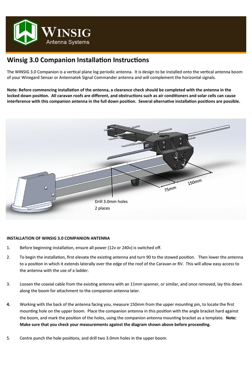
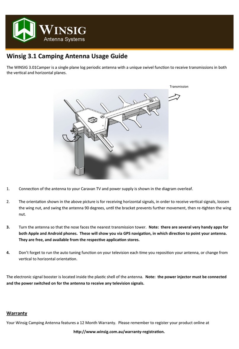
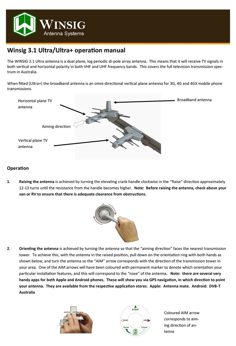
Winsig 3.1 Ultra Plus Retrofit User manual

Antenna Systems
Winsig 3.1 Ultra Plus Retrot Installaon Instrucons
The WINSIG 3.1 Ultra Retrot antenna is a horizontal and vercal plane log periodic antenna. It is designed to be installed onto
the exisng mounng hardware from a Winegard Sensar (including Sensar HV), or Antennatek Signal commander antenna.
Designed and manufactured in Australia, specically for Australian condions, this antenna will provide superior signal capabil-
ity to the unit it replaces in all situaons.
REMOVAL OF EXISTING ANTENNA
1. Before beginning installaon, ensure all power (12v or 240v) is switched o.
2. To begin the installaon, rst elevate the exisng antenna and turn 90 to the stowed posion. Then lower the antenna
to a posion in which it extends laterally over the edge of the roof of the Caravan or RV. This will allow easy access to
the antenna with the use of a ladder.
3. Loosen the upper coaxial cable connecon from the exisng antenna with n 11mm spanner, or similar, and once re-
moved, cut the F-type connector o the cable , and removed the coaxial cable from inside the antenna boom. Note: do
not disturb the coaxial cable at the roof mounng posion. This could lead to a leak in the roof of the van.
4. Using a pair of needle nosed pliers, remove the clips(2) from the lower pivot pins and slide the pivot pins out of the low-
er rotang housing. The exisng antenna can now be set aside, but retain the plasc raising gear segment, as this will
be re-used for the new Winsig antenna.
INSTALLATION OF WINSIG 3.1 ULTRA ANTENNA
5. Slide the gear segment from the original antenna into the upper aachment boom, with the segment oriented as shown
above, and locate both of these into the rotang gear housing (the upper aachment boom has no aached compo-
nents). Align the internal gears, and insert a new clevis pin in the upper hole through all three components. Secure the
clevis pin with a retaining clip (provided). Note: it is not important at what angle the gears are meshed, but horizontal
or slightly above, works best.
6. The lower boom can now be installed to the lower hole of the rotang housing, with the bump stop oriented toward
the roof of the van. Insert a second clevis pin, and secure with a retaining clip in the same manner as for the upper
boom.
Retaining clip detail—opposite side

Antenna Systems
7. The horizontal (ultra) antenna assembly can now be slid into place at the other end of each boom, and secured using the
nal two clevis pins, and retaining clips. This secures the antenna assembly, and allows it to move through its full mo-
on. Note: There are two possible orientaons for the horizontal antenna, based on your choice at me of purchase.
The correct hole for the upper pin is marked LH or RH on the antenna mounng bracket. The correct lower hole is
diagonally opposite, as shown below.
8. Now install the vercal plane antenna onto the top tube. Slide the antenna underneath the horizontal antenna onto
the top boom, aligning it with the exisng holes, as shown. Secure the antenna to the top boom using the two 8G self
tapping screws provided. These should be hand ght. Note: If using a cordless drill or driver, be careful to set a low
torque seng inially, so as not to strip the formed thread in the aluminium upper boom.

Antenna Systems
9. The coaxial cables many now be installed. First lower the antenna assembly, and aach the Horizontal antenna to the
vercal antenna. This requires a shiing spanner. Note: The connectors have inbuilt rubber sealing mechanisms, and
so the need be made rm, but not over ght. Slide the connector boot on the cable over the connector, and the hori-
zontal antenna installaon is complete.
10. Following the roung shown below, aach the signal booster to the mounng boom. This will be achieved by removing
the adhesive paper from the underside of the booster and aaching it midway between the cable e retainers Note: It
is very important not to bend the RF cable into ght radii, gently bend the cable into generous radii with your
thumbs. This will damage the internal insulaon, and aect the resulng recepon of the antenna.
11. Now cut the exisng antenna cable from the caravan to a length of 650 mm from the van roof. Install the suppled rub-
ber boot onto the exisng cable, and then aach the new connector provided. Note: Detailed installaon instrucons
for connector are provided on following page.

Antenna Systems
We love feedback. Please like our page on Facebook and send us an e-mail with your thoughts or a photo of your new installa-
on at enq[email protected] . We will try to make sure your photo makes it onto our page.
12. The nal connecon of the caravan cable to the lower point on the signal booster can now be made. As before, ghten
rmly, slide the rubber boot in place.
13. Remove the backing from the alignment decal, and install this on the boom of the direconal handle over the exisng
scker. Note: The home arrow head should be aligned with the pointer on the direconal handle
ROUTING THE BROADBAND CABLE
14. Insert the provided clear plasc rtree cable e retainer into the free pivot (below le).
15. Route the broadband antenna cable as shown (below le) and fasten with the provided cable e.
16. The coaxial cables for both the Television antenna, and the broadband antenna may now be retained with the provided
cable es as show in the gure (below right). In each case the cable es should fasten both cables to the black retainers
rmly.
The installaon is now complete. Return to the inside of the van, fully raise the antenna and orient toward the signal source.
Make sure the power supply (240v AC or 12v DC) is switched on, and remember to retune your TV, as you should now be re-
ceiving more channels in both the vercal and horizontal planes.
Your broadband antenna is omni-direconal, and as a consequence does not require orientaon. In this way the need to aim
the TV antenna toward the nearest transmier will not aect the mobile broadband performance.
Warranty
Your Winsig Camping Antenna features a 12 Month Warranty. Please remember to register your product online at
hp://www.winsig.com.au/warranty-registraon.
Fir tree cable e retainer
Cable es around both cables

Antenna Systems
Winsig 3.1 Connector to coaxial cable installaon
4. Once the cable has been prepared, slip the provided push-on connector
over the cable. The cable must be installed as far as it will go, such that
the centre copper conductor protrudes from the end of the connector
by a few millimetres.
5. Pull backward on the connector to ensure that the small nes have en-
gaged, and you connector is rmly in place.
Note: The provided connector is suitable for quad shielded RG6 coaxial ca-
ble. If the retainer nes on the connector have not engaged, your van may
have a smaller diameter (dual shielded) cable installed. As every van instal-
laon is dierent, we do not provide mulple connectors in each kit, howev-
er these connectors can be obtained by contacng us.
1. Strip outer plasc cover 12mm from end of cable.
2. Trim away all steel braid and aluminium foil unl white plasc insulator
is exposed. Some cable has two layers of this braid and foil. All must be
removed.
3. Remove 6mm of inner insulaon, whilst being careful no to nick the cen-
tre copper conductor.
Note: a cable stripper designed specically for coaxial cables will achieve a
neat and easy result if you have one, but this process can be achieved with a
sharp ulity knife if care is taken.
Before commencing the preparaon of your cable, slip the rubber protector boot onto the cable, and slide it out of the way to
allow easy access to the end to be terminated.

Antenna Systems
Winsig 3.1 Ultra Retrot alternate conguraons
Winsig 3.1 Ultra Retrot - Le Hand Installaon
Winsig 3.1 Ultra Retrot - Hybrid Installaon


Antenna Systems
Winsig 3.1 Ultra Plus Retrot Quality Assurance check sheet
Funconal test
Horizontal array
Vercal array
Amplier
In the box
Horizontal antenna (1)
Vercal antenna (1)
In-line amplier (1)
Mounng booms inc. bump stop and cable e retainers (2)
F-type RG6 coaxial cable connector (1)
RF connector boot—Black (1)
Clevis pins (4)
Clevis retaining clips (4)
10G x 12mm screws (2)
Cable e retainer—rtree (1)
100mm cable es (3)
Cable gland (1)
Patch cable SMA—TS9 (1)
Broadband wallplate (1)
LTE Low pass lter (1)
TV cable (1)
Aiming decal (1)
Table of contents
Other Winsig Antenna manuals
Popular Antenna manuals by other brands

Panorama Antennas
Panorama Antennas LP MM Series installation instructions

Dell
Dell Precision Compact 3260 installation guide

TracVision
TracVision C3 installation guide

Fractus Antennas
Fractus Antennas FR05-S1-NO-1-003 user manual

GME
GME AE2000 instruction manual

Thrane&Thrane
Thrane&Thrane Explorer 527 Getting started