- 7 -
Chapter 2 Terminal connection
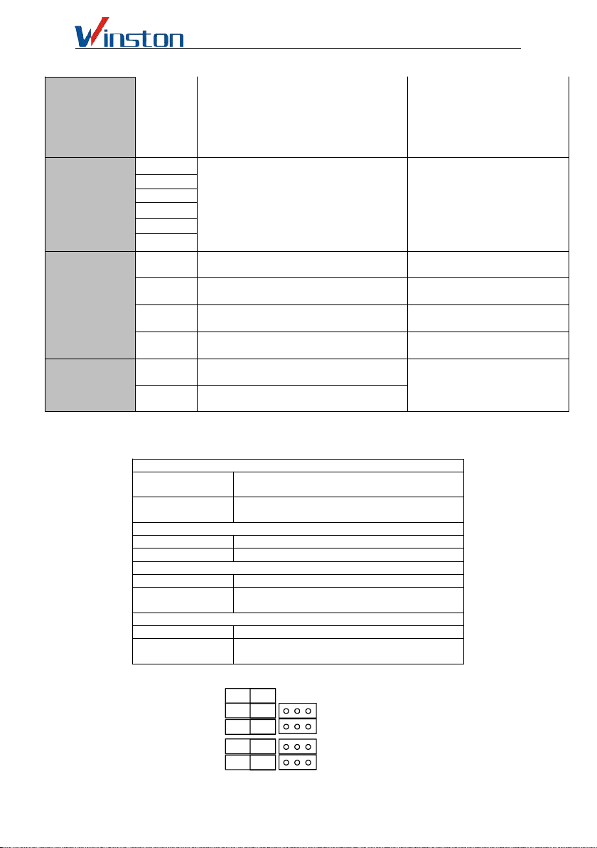
2.1 The main circuit terminals are described below:
Table 4.1 Main circuit terminal function description
Terminal name function declaration
R S T Three-phase power input terminal
U V W Three-phase AC motor terminals
P+ P- External brake unit reserved terminal
P+ PB External brake resistance reserved terminals (30 kW
and below)
P+ P1 External DC reactor reservation terminal
G/PE Earth terminal
2.2 Terminal of control loop
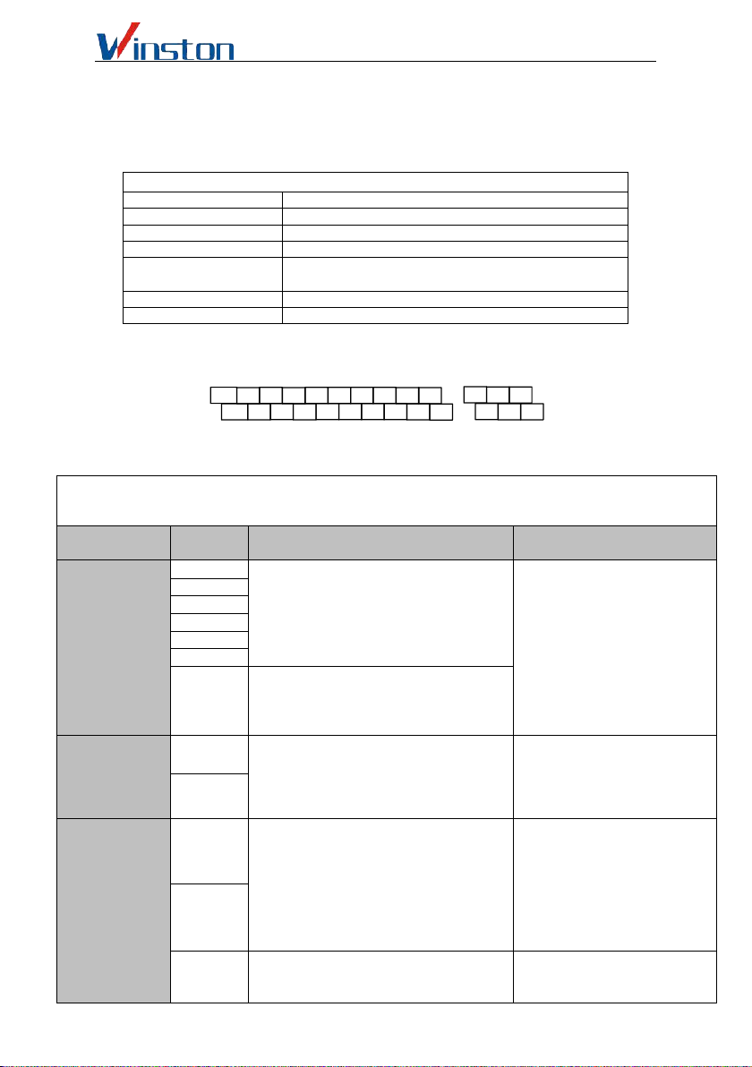
2.1 Distribution of control terminal of control panel
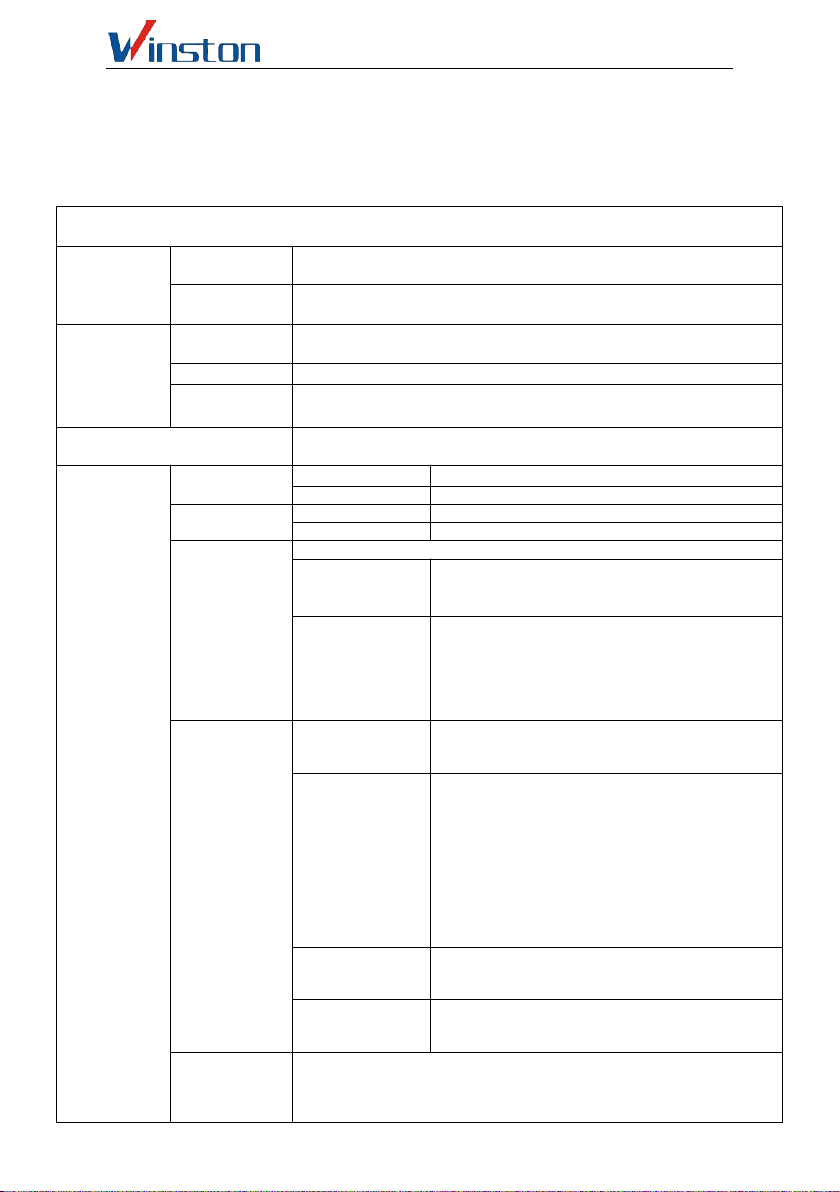
2.1 Function Description of Control Circuit Terminal
Category Terminal
label Function Description Specifications
Multifunctional
digital input
terminal DI
DI1 the short-time connection between DI
(DI1, DI2, DI3, DI4, DI5, DI6, DI7) is
effective, and its function is set by
parameter F07.00~COMF07.06,
respectively ,(common end: COM). INPUT,0-24 V level signal,
low level effective 5 mA.
DI2
DI3
DI4
DI5
DI6
DI7
DI7 can be used as a common
multi-function terminal, but also
programmable as a high-speed pulse input
port, see F07.06 function description.
Multifunctional
Digital Output
Terminal DO
DO1
DO (DO1, DO2) is a multifunctional
collector with open circuit output of up to 62
kinds. For details, see F07.18、F07.19
description of terminal function。
Opto coupler isolation, open
collector output, output voltage
range :0 V-24V
Output current range:
0mA-50mA
DO2
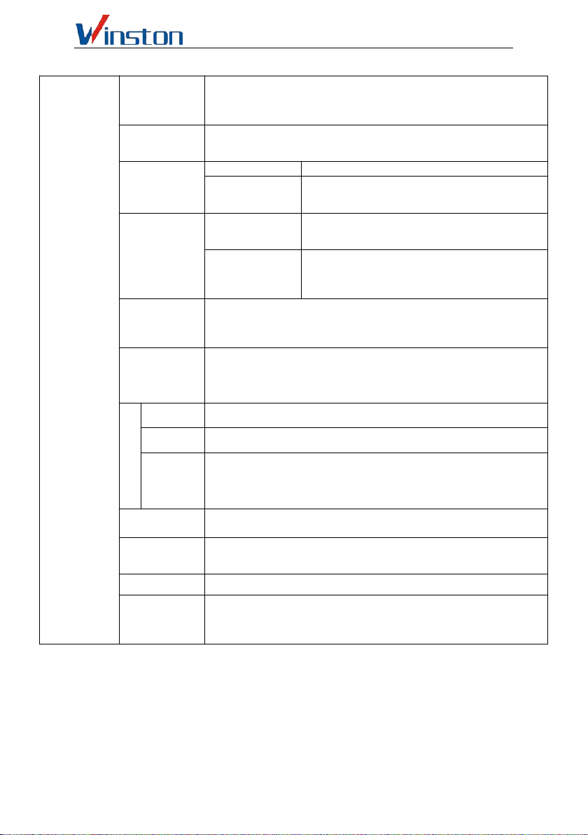
AO of analog
input AI output
terminals
AI1
AI1 receive analog voltage / current input,
voltage, current selected by jumper JP3,
factory default input voltage, if you want to
input is current, just adjust jumper cap to
Cin position; AI2 only receive voltage input.
Range setting see function code
F06.01~F06.10 description. (Reference:
GND)
INPUT, input voltage
range :0~10 V (input
impedance :100 KΩ), input
current range :0~20 input
impedance :500Ω).
AI2
AO1
AO1 provide the output of analog
voltage/current quantity, can represent 14
kinds of physical quantity, output voltage,
OUTPUT,0~10 V DC voltage.
The output voltage of the AO1、
TB1
TA1 TC1
AI1 AI2 GND AO2 DI7 DO1
DI1 DI3 DI5 24V
10V GND AO1 485+ DI6 COM
485- DI2 DI4 DO2 TB2
TA2 TC2