Digital Technology & New Innovation !!!
Instruction Manual
WP-3000 Series
Digital Indicators
Contents
WARNING / CAUTION / NOTE 1P
1. Checking the
Accessories 1P
2
. Part Name 1,2P
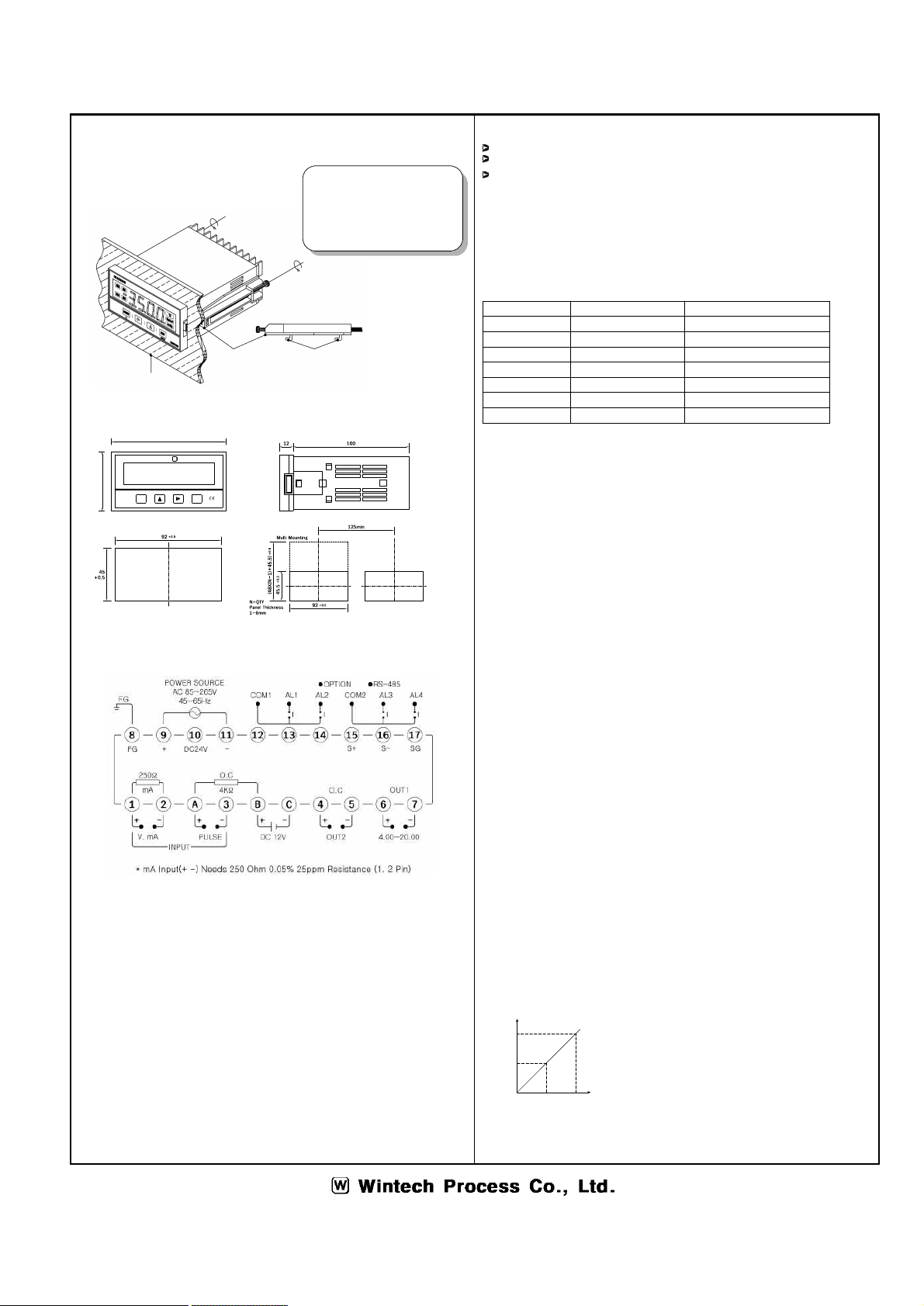
3. Installation
2P
4.
Terminal Diagram 2P
5.
Feature 2P
6.
General Specification 2P
7
. Major Functions 3P
8
. Operation and Setting Mode 3,4P
※ Be sure to observe following warning / cautions and
those provided in the text. In order to secure safety in
handing the instrument.
WARNING
- General
‣ In order to prevent electric shock, be sure to
disconnected this instrument from the main power
source when wiring.
- Protective Grounding
‣ In order to prevent electric shock ; be sure to
provided protective grounding prior to turning on this
instrument. Do not cut a protective
grounding conductor disconnected protective grounding.
- Power Source
‣ Make sure that the supply voltage for this
instrument conforms to the voltage source.
‣ Attach protective cover prior to turning on this instrument.
- Fuse
‣ In order to prevent a fire, use only our specified fuse.
‣ Don't short-circuit a fuse.
- Working Environment
‣ Do not operate this instrument in the environment where it
is exposed to a combustible, explosive, corrosive gas or
water, steam.
- Input and Output wiring
‣ Provide input and output wiring after turning off the power.
CAUTION
- Inside of instrument
‣ Do not disassemble the inside of the instrument.
‣ Prevent inflow of dust, water, oil and wiring dregs in to the
instrument.
- Input and Output wiring
‣ Do not use empty terminals for other purposes such
as relaying, etc.
‣ Wire correctly after checking the polarity and purpose of the
terminal.
‣ When wiring the instrument, separate from high voltage
cables, power lines, and motor lines to prevent
inductive noise.
- Transportation
‣ When transporting this instrument or the equipment with this
instrument incorporated in it, take measures to prevent
opening the door and falling out the inner module.
NOTE
- Instruction manual
‣ Deliver this instruction manual to an end user.
3456
MODE
AU TO
EXIT
WP3000
AL3 °C
mmHg
bar
AL1
AL4 AL2
1
7
2
WWin t e ch P ro c e s s C o.
‣ Prior to handing the instrument be sure to read this manual.
‣ If you have any question on this manual or fine any errors
omissions in this manual, contact our sales representative
‣ After reading this manual, keep it carefully by the
instrument.
‣ When the manual, is lost or stained, contact our sales
representative.
‣ It is prohibited to copy or reproduce this manual without
our permission.
- Checking the accessories
‣ Upon delivery instrument, unpack and check its accessories
and appearance. if there are missing accessories or
damage on the appearance contact our dealer where you
purchased the instrument or our sales representative.
- Installation
‣ When installing this instrument, put on a protective gear
such as safety shoes, helmet, etc. for your safety.
- Maintenance
‣ Only our serviceman or persons authorized by
Wintech Process Co. are allowed to remove and take the
inner module, the main unit and printed circuit boards apart.
- Disposal
‣ Disposed the used products in a correct way.
‣ Do not incinerate plastics of m
aintenance parts and
replacement parts. A harmful gas mat be produced.
‣ To dis
posed of this instrument, consign to the special
agent as an industrial waste.
- Cleaning
‣ Use dry cloth to clean the surface of this instrument
‣ Do not use any organic solvent.
‣ Cleaning the instrument after turning off the power.
- Revisions
‣ This instruction manual is subject to change without prior
notice.
- Evasion of responsibility guarantee
‣ Be sure to observe the caution in operating, maintaining,
and repairing this instrument. We will not be responsible
for or
guarantee the damage resulting from
negligence of them.
1. Checking the
Accessories
When you received, please check the Insufficient
accessories and defective products shape.
If the lack of parts, please contact the company.
2. Part Name
① Measured value display
② Alarm condition display
③ Memorize the setting data and change the operation menu.
④ Into the data setting mode and collect the changed
location.
⑤ Change the data value.
⑥ Out of mode.
⑦ Unit