Wintex Agro MCL3 User manual

Wintex Agro, Vilhelmsborgvej 8C, DK-7700 Thisted
+45 97990800, contact@wintexagro.com, www.wintexagro.com
▪0-120 or 0-200 cm
▪For all soils
▪Robust construction
▪Fast and user-friendly
▪Efficient and reliable
WINTEX MCL3
Instruction manual
The future is in the soil -
and in professional soil samplers

Wintex Agro, Vilhelmsborgvej 8C, DK-7700 Thisted
+45 97990800, contact@wintexagro.com, www.wintexagro.com
Manufactured by: WINTEX AGRO
Vilhelmsborgvej 8C
DK-7700 Thisted
Type designation: WINTEX MCL3
Voltage: 12 volt DC
Year of production: 2023
FOR YOUR SAFETY
Use personal hearing protection.
- Do not move the soil sampler with the mast in vertical position, especially not on uneven fields or slopes.
- Consider stability when moving on slopes. Where possible, drive straight up or down the slope, not across it.
- Keep an open eye on bumps, holes, ruts and obstacles.
- Adjust the speed to the prevailing conditions.
- If the probe stops penetrating the soil without reaching the desired depth, you are most likely driving against a larger stone
causing damage to the sampler. Stop the sampling process, and take a new sample nearby.
- Do not place your foot under the soil sampler.
- Do not touch moving parts under the operation.
HARD SOILS - IMPORTANT
When sampling in hard soil, the sampler must be stopped and rotated every 30 cm. Under normal conditions, rotation must happen
in rotation mode only (without using the hammer). If the rotation in extremely hard soils is not carried out, it may be almost impossible
to retrieve the probe from full depth, even if the hammer drives down successfully. Careful penetration at the beginning will give the
operator a feeling of whether or not the above procedure is necessary.

Wintex Agro, Vilhelmsborgvej 8C, DK-7700 Thisted
+45 97990800, contact@wintexagro.com, www.wintexagro.com
1. STARTING THE WINTEX MCL3
1.1. Starting the soil sampler with a cold engine:
Set the choke, then close it.
Throttle lever at 30%.
Turn the start switch clockwise.
Release the start switch after start.
Run the engine, and gradually reduce the choke until smooth running is ensured.
1.2. Starting the soil sampler with a warm engine:
The same start procedure as with the cold engine, but with the choke open.
2. OPERATION
All sampling operations are hydraulically operated from the control panel.
There are four separate functions:
- Lifting the mast
- Positioning the mast on the ground
- Getting the probe into the ground
- Rotating the probe
A special valve sequence control ensures that maximum pressure is
automatically obtained under all conditions.
2.1. Raise the mast vertically using the left valve lever (no.1 on the picture above).
2.2. Place the foot of the soil sampler onto the ground.
2.3. Using the valve lever second from left (no. 2 on the picture above), lower the mast down to the ground, until the weight of the
soil sampler rests on the foot.
2.4. Align the probe with the hole in the bottom plate.
1
3
2
4

Wintex Agro, Vilhelmsborgvej 8C, DK-7700 Thisted
+45 97990800, contact@wintexagro.com, www.wintexagro.com
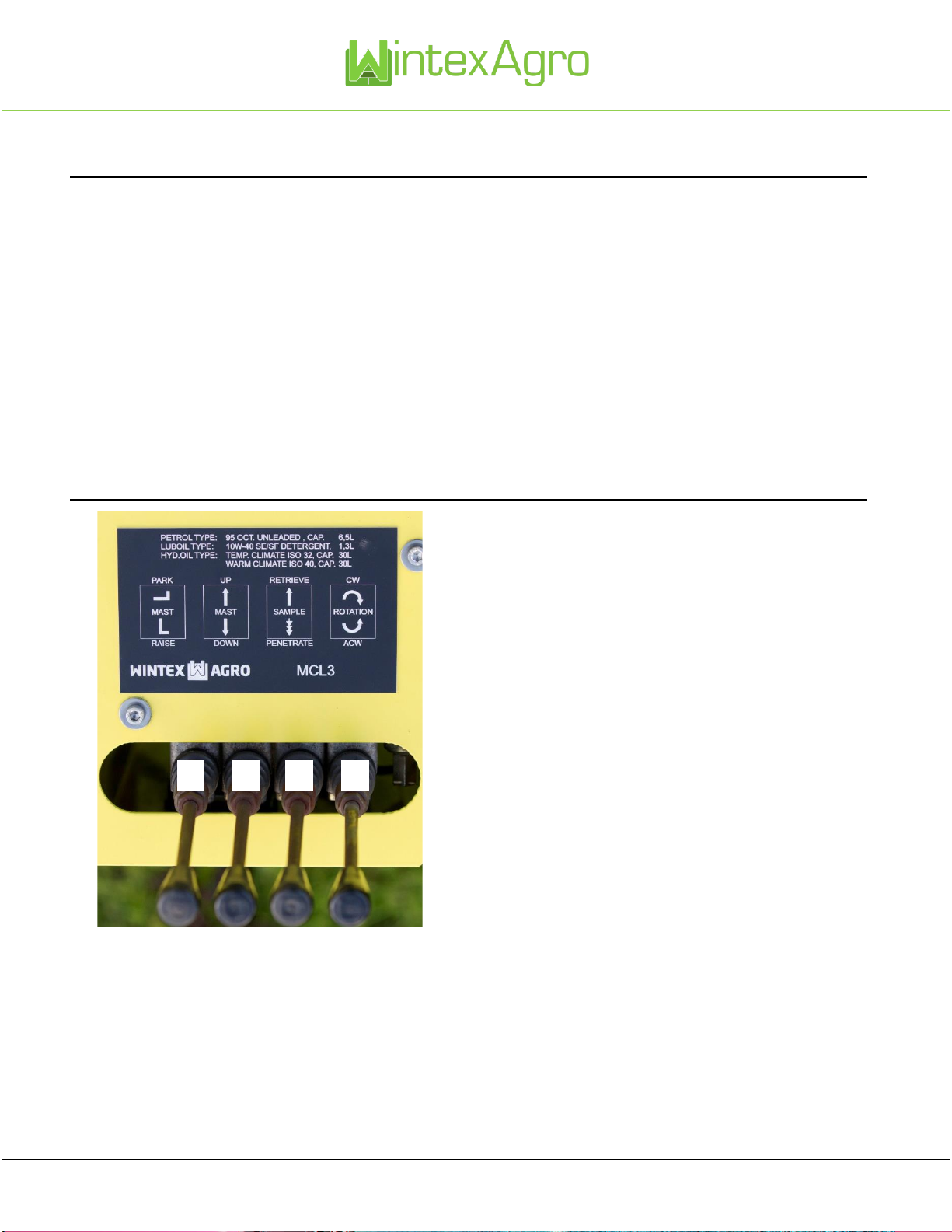
2.5. Using the valve lever second from left in penetrate mode (no. 3 on the picture above), carefully press the probe into the
ground until resistance is sufficient to start the hammer.
Note: Avoid hammering without resistance for long periods.
2.6. Give full opening to the valve in penetrate mode (push the handle down). The probe will penetrate the soil. When meeting
resistance, the hydraulic hammer will automatically start, and a synchronized sequence between the hammer and the cylinders
ensures optimum soil penetration without the operator’s need for participation.
2.7. When the probe has penetrated the soil down to the required depth, release the valve lever third from left (no. 3 on the picture
above) from the penetrate mode (mid position). Penetration will then cease.
2.8. Using the lever for rotation (no. 4 on the picture above), rotate the probe 180 degrees from side to side and stop it in the mid-
position.
2.9. Retrieve the sample by placing the valve lever (no. 3 on the picture above) into retrieve position.
2.10. Remove the soil sample from the slit by using the scraper so that the sample falls into the sampling scoop. It is common to
take soil samples for every 30 cm, e. g. 0-30 cm, 30-60 cm, 60-90 cm.
2.11. Empty the sampling scoop into the relevant soil bin. The soil of the samples can then be mixed and sent to the laboratory to
be analyzed.
3. REMOVING THE PROBE
Rotate the probe into a suitable position for removing the bolt for the probe. Remove one split pin, and then remove the bolt for the
probe. Relieve the pressure carefully by lifting the probe with your hand.
Be aware: The probe has sharp edges!
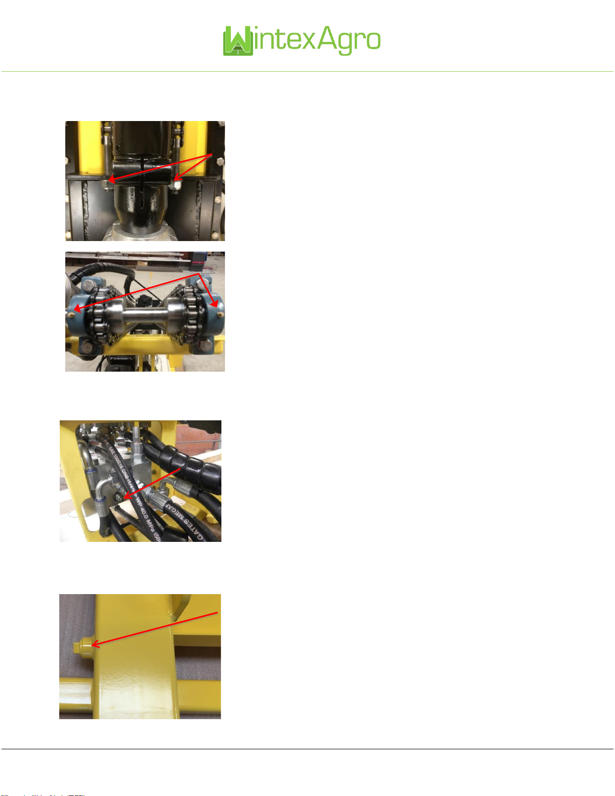
4. HYDRAULIC SYSTEM
The maximum system pressure should be set to 110-120 bar.
The operation of the probe is based on a combination of special valves in the valve block. When activating the valve lever
“penetration”, hydraulic oil is supplied to the two-stage pressure settings, low pressure and high-pressure setting. The low-pressure
stage actuates the cylinder downwards without hammer operation.
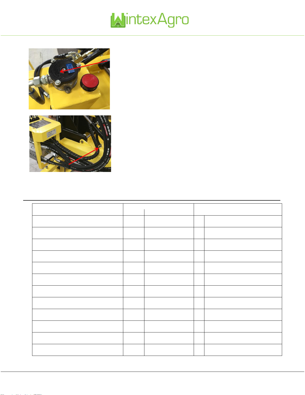
To adjust the two-stage pressure, the two-stage pressure valve must be screwed out as far as possible (anti-clockwise). With the
actuating lever set in penetration mode screw in the adjustment screw until the bottom plate of the soil sampler is just about to lift from
the ground. Lock the adjustment screw in this position.

Wintex Agro, Vilhelmsborgvej 8C, DK-7700 Thisted
+45 97990800, contact@wintexagro.com, www.wintexagro.com
5. TRANSPORTATION
5.1. Lift the foot from ground, using the valve (no. 2 on the picture above) in mast up mode.
5.2. Park the mast with the lever (no. 1 on the picture above) in mast park mode.
5.3. Switch off the petrol engine with the ignition key.
5.4. Close the valve for petrol supply when transporting the soil sampler from site to site, or when the soil sampler is not in use.
6. MAINTENANCE
Weekly
General:
Check the machine for oil leakage.
Loose nuts and bolts and check for defective parts and wear.
Amend by tightening and fitting new parts if necessary.
Hammer system:
Open the hammer clasp on the hammer and withdraw the striker.
The striker should be examined for wear, and the shank greased with moly grease (MoS2).
Replace the striker in the hammer and close the clasp.
Connection slide to cylinder:
Check the six nuts and bolts holding the main slide to the feed cylinder for tightness.
Tighten if necessary.
Hammer clamp:
Check for tightness.
Honda engine:
Maintenance as recommended in the Honda owner’s manual for GX390 engine.
Annually
Service:
Change oil and return filter. The soil sampler is pre-filled with Equivis XV46 oil.
Check and change suction strainer if necessary.

Wintex Agro, Vilhelmsborgvej 8C, DK-7700 Thisted
+45 97990800, contact@wintexagro.com, www.wintexagro.com
6.1. Tightening and lubricating chains
Tighten the chains by tightening the nuts.
It is important to lubricate the chain with oil.
Lubricate the grease nipples.
6.2. Adjusting the pressure for hammer and probe down
To adjust the pressure, unscrew the Allen screw.
Decrease the pressure by screwing the Allen screw anti-clockwise.
Increase the pressure by screwing the Allen screw clockwise.
6.3. Changing oil and return filter
Remove the two drain plugs (one drain plug on each side).
Empty the tank for oil.

Wintex Agro, Vilhelmsborgvej 8C, DK-7700 Thisted
+45 97990800, contact@wintexagro.com, www.wintexagro.com
After 50-100 hours in use the return filter must be changed.
Remove the lit of the filter housing.
Remove the return filter and insert a new one.
Remember to check the suction strainer and change it if necessary.
7. PROBLEM SOLVING
Problem
Possible causes to be controlled
Code list for possible causes
by user:
skilled technician:
Honda motor fails to start
1,2,3
3
1
Empty tank
No hydraulic system pressure
4
4,5,6
2
Flat battery
No vertical mast movement
-
4,5,6,7,8
3
See user manual for Honda motor
No penetration
4
4,6,9,10,11,25
4
Defect coupling for hydraulic pump
No retrieval
4
4,8,10,11
5
Defect relieve valve in control panel
Hammer fails to start
4
4,8,9,15,17,24
6
Defect hydraulic pump
Hammer is weak
-
12,13
7
Leaking counter valve in valve block
Hammer oil leakage
14,16
14,16,23
8
Defect four-way valve actuator
No rotation
4,18,19
4,18,19
9
Defect pressure regulator in block
Creep in mast, park cylinders
20
20
10
Defect counter valve in block
Feed cylinder falls unactuated
-
21
11
Defect counter valve
Uneven stroke, slow feed up
-
21
12
Defect membrane

Wintex Agro, Vilhelmsborgvej 8C, DK-7700 Thisted
+45 97990800, contact@wintexagro.com, www.wintexagro.com
Feed cylinder moves without actuation
-
22
13
Worn hammer
Excessive vibration in hammer tubes
-
12
14
Worn seals
Excessive vibration in engine mountings
23
23
15
Defect start valve in hammer
Excessive heat in oil tank, oil mist from filler cap
23
23
16
Loose screw threads
17
Hammer shuttle valve incorrectly
fitted
18
Broken gear wheel
19
Leaking seals
20
Counter valve leaking
(mounted on cylinder)
21
Counter valve spring too weak
22
Loose retaining latch on control panel
23
Too much engine speed,
excessive oil flow
24
Hammer shuttle valve seized
25
Pilot piston seized
8. FAULT LOCATION HAMMER
The hydraulic hammer contains a gas/oil accumulator which is hermetically charged with nitrogen gas and necessary for the correct
function of the hammer.
After using the soil sampler for a long time (several years), the pressure membrane could become defect causing gas leakage. This
failure can be observed by the operator. The hammer would lose penetration power, and the hydraulic tubes for the hammer which
are feeding oil to and from the hammer would shake violently. The hammer must not be used in this condition. It would require
maintenance, a new membrane and recharging with gas. This service can be carried out by a skilled Technician, but a special tool is
required for the job. Consult your dealer.
Before starting locating faults, check that the oil flow from the power source is correct, and that the pressure relief valve is set correctly.

Wintex Agro, Vilhelmsborgvej 8C, DK-7700 Thisted
+45 97990800, contact@wintexagro.com, www.wintexagro.com
PROBLEM
CAUSE
POSSIBLE SOLUTIONS
The hammer does not start.
There is pressure in hose P.
1) The oil supply goes to connection T
instead of connection P.
2) The striking piston is stuck in the
cylinder.
1) Switch hose P and hose T.
2) Polish or replace the components.
The hammer works irregularly.
1) There are impurities in the hydraulic
oil.
2) The oil level in the power source is
too low.
1) Replace the oil and the oil filter.
2) Add hydraulic oil.
The hammer performs badly.
1) There is an internal leak.
2) The oil flow from the power source
towards the hammer is incorrect.
3) The accumulator pressure is too low.
4) The return pressure is too high.
1) Dismount the valve housing and replace the
o-rings.
2) Check the oil flow.
3) Charge the accumulator with nitrogen or
replace it.
4) Check the power source, the hoses and the
filter.
Table of contents