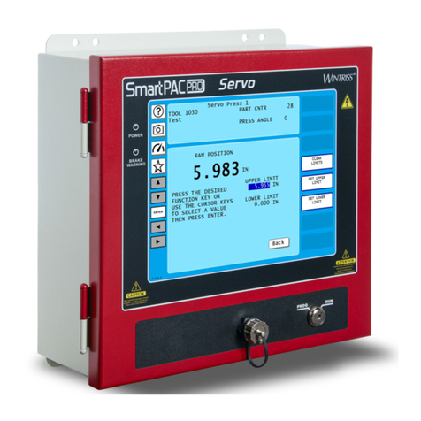
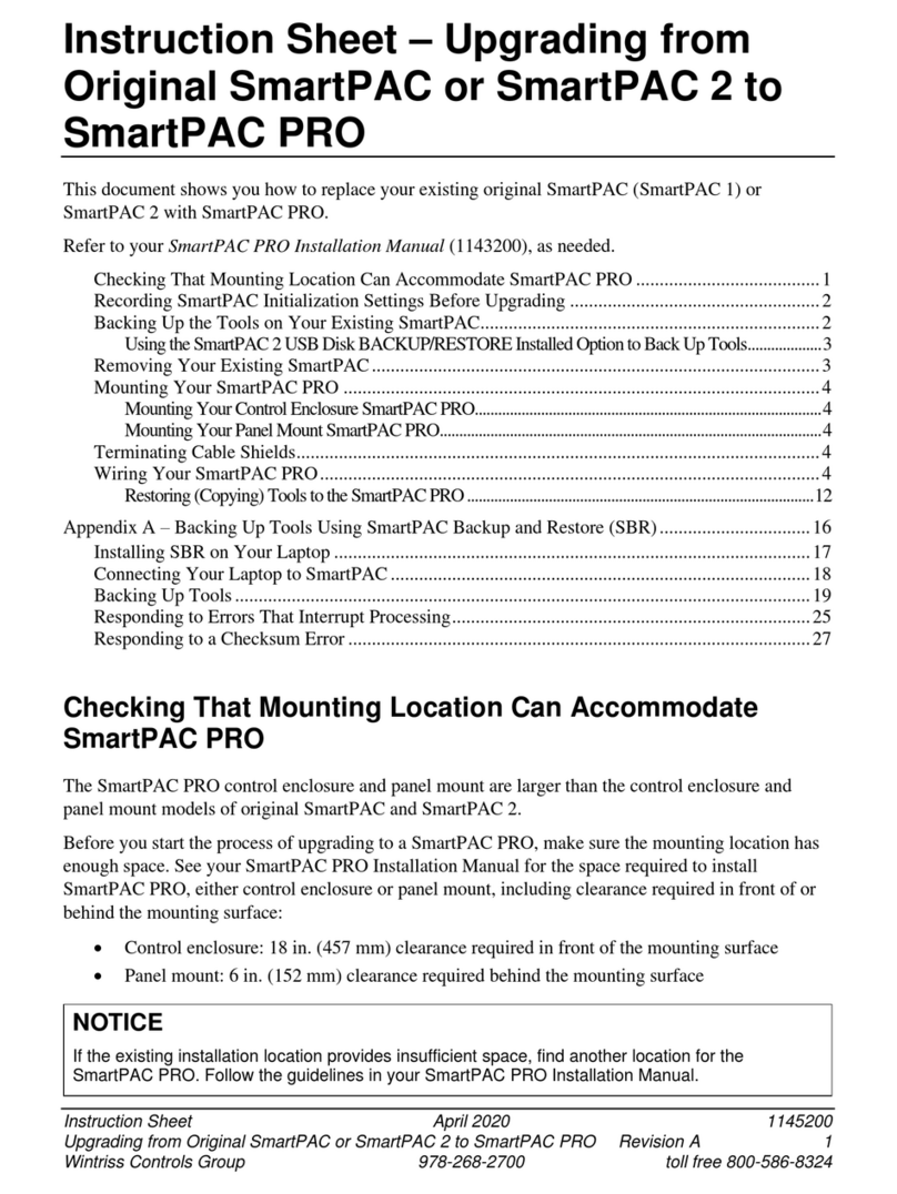
Wintriss SmartPAC PRO Use and care manual

Tech Support Hotline 800-586-8324 8-5 EST
www.wintriss.com
®
®
Wintriss Controls Group, LLC
100 Discovery Way
Unit 110
Acton MA 01720 USA
Phone (800) 586-8324
Fax (978) 263-2048
PRINTED IN USA


Thank you for purchasing a Wintriss product. We appreciate your business and want to do whatever
we can to ensure your satisfaction. Wintriss products are built to stay on the job day after day, and are
backed by an ironclad guarantee, international standards approvals, and unbeatable support.
Whenever you need assistance or service, we back all our products with excellent spare parts
inventories, training programs, and prompt repair service. We would like to share with you a list of
service options–probably the largest number of service options offered in the industry.
•Technical Assistance
We offer a toll-free line for technical assistance. Call our Wintriss Technical Support Hotline at
1-800-586-TECH (8324) should you have any questions about your equipment. Our technical staff is
ready to assist you Monday through Friday, 8 a.m. to 5 p.m. EST. In many cases our experienced
technical staff can resolve your inquiry right over the phone.
•Return Authorization
Please call our “800” number for a return authorization (RMA) number to return a product for repair.
Returned goods must arrive freight prepaid. In order to process your return quickly, we ask that you
provide us with the following pertinent information when you call: purchase order number, shipping
address, contact name and telephone number, and product type. The assigned RMA number should
appear on all packages returned to Wintriss Controls Group to ensure prompt service.
At the time of requesting an RMA, you will be quoted a flat-rate repair price for the product you are
returning. We ask that you either fax us a PO for that amount or enclose the PO with the returned
item. This will enable us to ship the item back to you as soon as the repair has been completed. If the
item cannot be repaired or there are additional charges, you will be contacted for approval.
Please be sure to carefully pack all returned items and ship to our Acton, MA location.
•Expedited Repair Program
Rush service providing 48 hour turnaround is available for most products upon request. An Expedite
Fee will be applied to our standard repair rate.
•Board Exchange Program
If your needs are urgent, you can take advantage of our Board Exchange (EX) program. Call our
“800” number between 8 a.m. and 5 p.m. EST and we will send a replacement to you overnight. A fee
does apply to this service. Contact Wintriss Technical Support at 800-586-8324 for details.
•Service Center
Our Service Center for product service is located at our headquarters in Acton, MA. If your
equipment requires repair, please contact us at 800-586-8324 to obtain a return authorization number.
Nationwide field service is also available. Contact the Wintriss Technical Support group at
800-586-8324.
•Product Training
We also offer both product training and maintenance/troubleshooting courses at our Acton, MA and
Chicago-area facilities. On-site training is available from the factory or through your local Wintriss
representative.
•Restocking Charge
Returned goods are subject to a 20% restocking charge if returned for credit. The minimum charge is
$50, not to exceed $250 per item.
Whatever the product, we are committed to satisfying you with innovative engineering, quality
construction, reliable performance, and ongoing, helpful support. Call us whenever you need
assistance.


SmartPAC PRO - WPC 2000 Integration Manual 1143300
Table of Contents 5
Table of Contents
Chapter 1 – Introduction to SmartPAC PRO with WPC 2000 Integration ......................17
Chapter 2 – Installation.......................................................................................................19
Use This Manual Along with Your SmartPAC PRO and WPC 2000 Manuals............................. 22
Install your SmartPAC PRO According to the SmartPAC PRO Installation Manual ................... 22
Install Your WPC 2000 According to WPC 2000 Installation Manual......................................... 22
Installing the Optional Flywheel Speed Sensor ................................................................................................23
Wiring between WPC 2000 and SmartPAC PRO ......................................................................... 25
Connecting the Resolver Wiring Between SmartPAC PRO and WPC 2000 ..............................................27
Connecting Communications Wiring................................................................................................................29
Connecting Stop Circuits and Input Check Circuit ..........................................................................................29
Setting the Input Check Voltage Switch....................................................................................................30
Setting Up SmartPAC PRO with WPC 2000................................................................................. 31
Turning on Power to SmartPAC PRO and WPC 2000...................................................................................31
Problems at Startup ......................................................................................................................................32
“PRESS CONTROL” Does Not Appear in SmartPAC PRO Initialization Menu..............................32
Verifying the Installation of DiProPAC and ProCamPAC ............................................................ 34
Initializing WPC 2000 Parameters During Installation ................................................................. 34
Entering Initialization Mode ...............................................................................................................................34
Creating a New Tool Setup............................................................................................................ 37
Performing Brake Monitor Tests and Making Settings ................................................................. 38
Final Checkout............................................................................................................................... 38
Installation Verification (WPC 2000 Manual)............................................................................... 39
Final Checkout (SmartPAC PRO Installation Manual) ................................................................. 39
Chapter 3 – Initialization.....................................................................................................43
Entering Initialization Mode.......................................................................................................... 43
Making Press Control Settings in Initialization mode ................................................................... 44
USER INTERLOCKS ................................................................................................................... 46
PRESS PARAMETERS ................................................................................................................ 50
Setting the Top-stop Angle..................................................................................................................................51
Setting the Auto Carry-up Angle........................................................................................................................52
Setting Micro-inch Time and Angle ..................................................................................................................53
Setting Clutch and Counterbalance Air Pressure Limits..................................................................................53
Setting the Stop-time Limit and Start-time Limit .............................................................................................54
Setting the Shutdown Time (Optional)..............................................................................................................54
Setting Flywheel Timer (Optional Hardware Required) .................................................................................55
Setting the ACTS Angle (Optional)...................................................................................................................55
Selecting Pressure Units ......................................................................................................................................55
INPUT STATUS............................................................................................................................ 56
BUTTONS/SWITCHES....................................................................................................................................57
ESTOPS/TOP STOPS ........................................................................................................................................58
INTERLOCKS ....................................................................................................................................................58
TRANSDUCERS................................................................................................................................................59
LUBE CONTROL I/O STATUS......................................................................................................................59
PRESS OPTIONS.......................................................................................................................... 60
Making Settings for Option Switches................................................................................................................61
Making Operator Mode Settings........................................................................................................................62
Dual Operators..............................................................................................................................................63

1143300 SmartPAC PRO - WPC 2000 Integration Manual
6 Table of Contents
Automatic Mode...........................................................................................................................................64
Two Hand Only............................................................................................................................................65
Additional Security........................................................................................................................ 66
Wiring an Optional Keylock Switch to Prevent Changes to WPC 2000 Settings........................................66
Chapter 4 – Program...........................................................................................................67
Entering and Exiting Program Mode............................................................................................. 67
PRESS CONTROL ....................................................................................................................... 68
Setting Top Stop Angle for the Selected Tool ..................................................................................................70
Setting Maximum and Minimum Press Speed for the Selected Tool............................................................71
Setting Counterbalance Setpoint for the Selected Tool....................................................................................72
Chapter 5 – Run ..................................................................................................................73
Entering and Exiting Run Mode.................................................................................................... 73
Settings Locked, or Password Required ........................................................................................ 74
Loading a Tool .............................................................................................................................. 75
Show Overrun Angles .........................................................................................................................................76
BRAKE MONITOR...................................................................................................................... 77
Determining the Stopping Time of Your Press ........................................................................................77
Performing the 90° Stop-time Test.............................................................................................................77
Calculating the Safety Distance ..................................................................................................................77
PRESS CONTROL ....................................................................................................................... 77
Adjusting Program Settings ................................................................................................................................78
Displaying Overrun Sensor On/Off Angles......................................................................................................81
Operating the Press........................................................................................................................ 82
Responding to an Interrupted Stroke..................................................................................................................82
Selecting Operating Mode ..................................................................................................................................82
Operating the Press in Inch Mode ................................................................................................. 83
Top-stop in Inch....................................................................................................................................................84
Top-stop Bypass (Top-stop in Inch Disabled)..................................................................................................84
Micro-inch.....................................................................................................................................................84
Dead Motor Inch ..........................................................................................................................................85
Operating the Press in Single-stroke Mode.......................................................................................................85
Single-stroke, Two-hand Operation...........................................................................................................86
Single-stroke, One-hand Operation............................................................................................................87
Single-stroke, One-hand Control Operation..............................................................................................87
Single-stroke, Foot Operation.............................................................................................................................89
Operating the Press in Automatic Single-stroke Mode....................................................................................90
Operating the Press in Continuous Mode..........................................................................................................91
Continuous, Two-hand Operation..............................................................................................................91
Continuous, Foot Operation........................................................................................................................92
Operating the Press in Automatic Continuous On-demand Mode.........................................................93
Operating the Press in Bar Mode................................................................................................................93
Multiple Operator Stations ............................................................................................................ 94
Chapter 6 – Fault Messages...............................................................................................97
Responding to Fault Messages ...................................................................................................... 98
Lockout Message........................................................................................................................... 99
Brake Monitor Faults..................................................................................................................... 99
Brake Warning LED............................................................................................................................................99
Stop Time Exceeded............................................................................................................................................99
Messages for Press Control Problems ......................................................................................... 100

SmartPAC PRO - WPC 2000 Integration Manual 1143100
Table of Contents 7
Resolver Faults ...................................................................................................................................................102
Operational Faults ..............................................................................................................................................103
Inter-processor Failures......................................................................................................................................109
Input Buffer Test Failures..................................................................................................................................109
Air Pressure Limits Exceeded...........................................................................................................................110
Component Failures...........................................................................................................................................110
Customized Status Codes..................................................................................................................................111
Light Curtain Faults ...........................................................................................................................................113
Emergency-stop Circuit Driver Failure ...........................................................................................................114
Top-stop Circuit Driver Failure ........................................................................................................................115
Shadow Light Curtain Input Faults ..................................................................................................................115
DSV Interface and Lockout Relay Failures ....................................................................................................116
Loss of Rotation..................................................................................................................................................117
Internal Timing Input Failures ..........................................................................................................................117
Top-stop and Overrun Setting Faults ...............................................................................................................118
Overrun Limit Switch Fault ..............................................................................................................................118
Overrun Limit Switch Test Angle Fault ..........................................................................................................119
Overrun Limit Switch Setting Fault .................................................................................................................119
Internal Memory Failures..................................................................................................................................120
Counter Preset Reached Messages............................................................................................... 121
“Good parts counter preset reached”........................................................................................................121
“Strokes counter preset reached”..............................................................................................................121
“Batch # counter preset reached”..............................................................................................................121
Messages for Equipment or Brake Monitor Problems................................................................. 122
“Loss of rotation detected” ........................................................................................................................122
“Angle Resolver Failure” ..........................................................................................................................122
“Input check circuit failure” ......................................................................................................................122
E-Stop errors ...............................................................................................................................................123
“Inboard ram test failure” ..........................................................................................................................123
“Resolver signals incorrect” or “Resolver drive signal incorrect” ........................................................123
“Stop time exceeded”.................................................................................................................................123
Messages for Programming Problems ......................................................................................... 124
“No tool number has been loaded”...........................................................................................................124
“Tool number table checksum error”.......................................................................................................124
Messages for Sensor Faults.......................................................................................................... 125
“Green sensor missed”...............................................................................................................................125
“Green sensor actuated late” .....................................................................................................................125
“Green sensor failure”................................................................................................................................126
“Green constant fault”................................................................................................................................126
“Green quick check sensor actuated outside ready”...............................................................................126
“Green special fault” ..................................................................................................................................126
Fault message for yellow sensors: “This N/O sensor is grounded”....................................................126
Fault message for red sensors: “This N/C sensor is open” ..................................................................127
Miscellaneous Fault Messages..................................................................................................... 127
“Maximum press speed exceeded”..........................................................................................................127
“Minimum press speed exceeded”...........................................................................................................127
“The resolver position is different from when the unit was turned off”...............................................127
“One of the sensor auto enable counters is greater than 99”..................................................................127
“Loss of Communication at Address X”.................................................................................................128
Troubleshooting Using the Error/Event Log ............................................................................... 128
Resetting Ross DM2 DSV Faults ................................................................................................ 129

1143300 SmartPAC PRO - WPC 2000 Integration Manual
8 Table of Contents
Wiring Diagrams at End of Manual
Figure 1. WPC 2000 and SmartPAC PRO System Wiring
Figure 2. WPC 2000 and SmartPAC Pro 24 VDC System Wiring
List of Figures
Figure 1-1. Installation Overview ........................................................................................................ 18
Figure 2-1 . Installing the LMCS and Magnets ................................................................................... 24
Figure 2-2. SmartPAC PRO Board with Terminal Block Locations ................................................... 25
Figure 2-3. WPC 2000 Main Processor Board: Location of Important Components.......................... 26
Figure 2-4. Location of the Master-Slave Jumper on SmartPAC PRO Board..................................... 28
Figure 2-5. Main Program Menu ......................................................................................................... 32
Figure 2-6. SmartPAC PRO board, Rx and Tx LEDs.......................................................................... 33
Figure 2-7. Main Program Menu ......................................................................................................... 35
Figure 2-8. Main Initialization Menu................................................................................................... 35
Figure 2-9. Initialize SmartPAC System Screen.................................................................................. 36
Figure 2-10. Modules to Initialize, Select Module .............................................................................. 36
Figure 2-11. Modules to Initialize, Press Control selected .................................................................. 37
Figure 2-12. Initialize Press Control Warning and Confirmation........................................................ 37
Figure 2-13. LED Map, WPC 2000 Main Processor Board ................................................................ 41
Figure 3-1. Main Program Menu ......................................................................................................... 44
Figure 3-2. Main Initialization Menu................................................................................................... 45
Figure 3-3. WPC Initialization Menu .................................................................................................. 45
Figure 3-4. WPC Initialization Menu .................................................................................................. 47
Figure 3-5. Press Control User Interlock Menu................................................................................... 48
Figure 3-6. Select Stop Name Screen .................................................................................................. 48
Figure 3-7. SmartPAC PRO On-screen Keyboard............................................................................... 49
Figure 3-8. WPC Initialization Menu .................................................................................................. 50
Figure 3-9. Press Control Parameter Menu.......................................................................................... 50
Figure 3-10. Numeric Entry Window .................................................................................................. 51
Figure 3-11. WPC Initialization Menu ................................................................................................ 56
Figure 3-12. Display WPC Input Status Main Screen ......................................................................... 56
Figure 3-13. Buttons and Switches Status Screen................................................................................ 57
Figure 3-14. E-Stops and Top Stops Status Screen.............................................................................. 58
Figure 3-15. Interlock Group 1 Input Status........................................................................................ 58
Figure 3-16. WPC Transducer Input Status ......................................................................................... 59
Figure 3-17. Lube Control I/O Status .................................................................................................. 59
Figure 3-18. WPC Initialization Menu ................................................................................................ 60
Figure 3-19. Press Control Option Switch Menu................................................................................. 60
Figure 3-20. WPC Initialization Menu ................................................................................................ 61
Figure 3-21. Press Control Option Switch Menu – Showing Default Settings.................................... 62
Figure 3-22. WPC Initialization Menu – Dual Operators Screen Mode.............................................. 63
Figure 3-23. WPC Initialization Menu – Automatic Mode Setting ..................................................... 64
Figure 3-24. WPC Initialization Menu – Two Hand Only Setting ...................................................... 65
Figure 4-1. Main Program Menu ......................................................................................................... 67
Figure 4-2. Tool Manager Screen ........................................................................................................ 68
Figure 4-3. Tool Program Menu .......................................................................................................... 68

SmartPAC PRO - WPC 2000 Integration Manual 1143100
Table of Contents 9
Figure 4-4. Press Control Parameters Screen ....................................................................................... 69
Figure 4-5. Change Top Stop Angle..................................................................................................... 70
Figure 4-6. Change Maximum Press Speed ......................................................................................... 71
Figure 4-7. Change Minimum Press Speed.......................................................................................... 72
Figure 4-8. Change Counterbalance Setpoint....................................................................................... 72
Figure 5-1. Main Run Menu................................................................................................................. 73
Figure 5-2. Enter Password Screen ...................................................................................................... 74
Figure 5-3. No Tool Loaded Warning Window ................................................................................... 75
Figure 5-4. Main Program Screen ........................................................................................................ 75
Figure 5-5. Tool Screen........................................................................................................................ 76
Figure 5-6. Show Overrun Angles........................................................................................................ 76
Figure 5-7. Press Control Parameters Screen ....................................................................................... 78
Figure 5-8. Main Run Menu................................................................................................................. 79
Figure 5-9. Press Control Parameters Screen ....................................................................................... 79
Figure 5-10. Numeric Entry Window................................................................................................... 80
Figure 5-11. Maximum Press Speed Exceeded Error Message............................................................ 81
Figure 5-12. Press Control Parameters Screen Showing Overrun Angles Window............................. 81
Figure 5-13. Mode Select Menu........................................................................................................... 82
Figure 6-1. Error Code Window........................................................................................................... 98
Figure 6-2. Counter Preset Message Window...................................................................................... 98
Figure 6-3. WPC 2000 Display Showing Fault Code ........................................................................ 101
Figure 6-4. Ross DM2 DSV Showing Reset Button .......................................................................... 129
List of Tables
Table 2-1. Flywheel Speed Sensor Wiring Connections...................................................................... 24
Table 2-2. Resolver Wiring, SmartPAC PRO and WPC 2000............................................................. 28
Table 2-3. Communications Wiring, SmartPAC PRO to WPC 2000 .................................................. 29
Table 2-4. Stop and Input Check Wiring SmartPAC PRO to WPC 2000............................................ 30
Table 5-1. Instructions for Entering and Exiting Run Mode................................................................ 73
Table 6-1. Fault Codes: Significance of Initial Letter ........................................................................ 101
Table 6-2. Fault Codes for User Inputs .............................................................................................. 112
Table 6-3. Communication Errors: Option at Fault............................................................................ 128


SmartPAC PRO - WPC 2000 Integration Manual 1143100
How to Use this Manual 11
How to Use This Manual
This manual covers any additional information you need to install and operate the SmartPAC PRO
with WPC 2000 integrated product. Refer to the SmartPAC PRO and WPC 2000 manuals for most of
the instructions on installation, initialization, programming, and operation.
Chapter 1 – Introduction introduces the SmartPAC PRO and WPC 2000 integration.
Chapter 2 – Installation tells how to wire the SmartPAC PRO and WPC 2000 integration
Chapter 3 – Initialization shows you how to perform initialization operations relating to the
SmartPAC PRO – WPC 2000 integration.
Chapter 4 – Programming shows you how to perform programming tasks relating to the
SmartPAC PRO – WPC 2000 integration.
Chapter 5– Run shows you how operate the SmartPAC PRO – WPC 2000 integration.
The wiring diagrams at the end of the manual show connections for the SmartPAC PRO – WPC 2000
integration.
NOTICE
Download Wintriss product documents for the SmartPAC PRO and WPC 2000 integration, at
www.wintrissdocs.com


SmartPAC PRO - WPC 2000 Integration Manual 1143100
How to Use this Manual 13
Important Highlighted Information
Important danger, warning, caution, and notice information is highlighted throughout the manual as
follows:
DANGER
A DANGER symbol indicates an imminently hazardous situation, which, if not avoided, will result
in death or serious injury.
WARNING
A WARNING symbol indicates a potentially hazardous situation, which, if not avoided, could
result in death or serious injury.
CAUTION
A CAUTION symbol indicates a potentially hazardous situation, which, if not avoided, may result
in property damage.
NOTICE
A NOTICE symbol indicates important information that you should remember, including tips to aid
you in performance of your job.


15
WARRANTY
Wintriss Controls warrants that Wintriss electronic controls are free from defects in material and
workmanship under normal use and service for a period of one year (two years for Shadow light
curtains) from date of shipment. All software products (SFC/ LETS), electro-mechanical
assemblies, and sensors are warranted to be free from defects in material and workmanship under
normal use and service for a period of 90 days from date of shipment. Wintriss’s obligations under
this warranty are limited to repairing or replacing, at its discretion and at its factory or facility, any
products which shall, within the applicable period after shipment, be returned to Wintriss Controls
freight prepaid and which are, after examination, disclosed to the satisfaction of Wintriss to be
defective. This warranty shall not apply to any equipment which has been subjected to improper
installation, misuse, misapplication, negligence, accident, or unauthorized modification. The
provisions of this warranty do not extend the original warranty of any product which has either
been repaired or replaced by Wintriss Controls. No other warranty is expressed or implied.
Wintriss accepts no liability for damages, including any anticipated or lost profits, incidental
damages, consequential damages, costs, time charges, or other losses incurred in connection with
the purchase, installation, repair or operation of our products, or any part thereof.
Please note:
It is solely the user’s responsibility to properly install and maintain Wintriss controls and
equipment. Wintriss Controls manufactures its products to meet stringent specifications and cannot
assume responsibility for consequences arising from their misuse.
Wintriss Controls Group, LLC SmartPAC PRO - WPC 2000 Integration
100 Discovery Way INTEGRATION MANUAL
Unit 110 1143300
Acton, MA 01720 Wintriss Controls Group, LLC
Telephone: (800) 586-TECH (8324) Copyright 2018
(978) 268-2700
Fax: (978) 263-2048
Internet: http://www.wintriss.com


SmartPAC PRO - WPC 2000 Integration Manual 1143300
Chapter 1– Introduction to SmartPAC PRO with WPC 2000 Integration 17
Chapter 1 – Introduction to
SmartPAC PRO with WPC 2000
Integration
SmartPAC PRO integrated with WPC 2000 provides a comprehensive user interface for the Wintriss
Clutch/Brake control, bringing a multitude of press automation functions to one central location.
This manual gives you the information specific to the integration of SmartPAC PRO with WPC 2000.
Most of the information you need to install and use the integrated system is in the following manuals:
•SmartPAC PRO Installation Manual
•SmartPAC PRO User Manual
•WPC 2000 Installation Manual.
This Integration Manual provides the additional information needed to install and use the SmartPAC
PRO with WPC 2000 integration.
NOTICE
BEFORE YOU PROCEED WITH THIS INTEGRATION MANUAL, COMPLETE THE
FOLLOWING (SEE ALSO PAGE 22):
•Install your WPC 2000 according to the installation manual. Follow the installation procedures
up to, but not including Installation Verification.
•Install your SmartPAC PRO according to the installation manual. Follow the installation
procedure through Final Checkout.
•See the installation overview, Figure 1-1, next page.

1143300 SmartPAC PRO - WPC 2000 Integration Manual
18 Chapter 1– Introduction to SmartPAC PRO with WPC 2000 Integration
Figure 1-1. Installation Overview

SmartPAC PRO - WPC 2000 Integration Manual 1143300
Chapter 2 – Installation 19
Chapter 2 – Installation
Use This Manual Along with Your SmartPAC PRO and WPC 2000 Manuals............................. 22
Install your SmartPAC PRO According to the SmartPAC PRO Installation Manual ................... 22
Install Your WPC 2000 According to WPC 2000 Installation Manual......................................... 22
Installing the Optional Flywheel Speed Sensor ................................................................................................23
Wiring between WPC 2000 and SmartPAC PRO ......................................................................... 25
Connecting the Resolver Wiring Between SmartPAC PRO and WPC 2000 ..............................................27
Connecting Communications Wiring................................................................................................................29
Connecting Stop Circuits and Input Check Circuit ..........................................................................................29
Setting the Input Check Voltage Switch....................................................................................................30
Setting Up SmartPAC PRO with WPC 2000................................................................................. 31
Turning on Power to SmartPAC PRO and WPC 2000...................................................................................31
Problems at Startup ......................................................................................................................................32
“PRESS CONTROL” Does Not Appear in SmartPAC PRO Initialization Menu..............................32
Verifying the Installation of DiProPAC and ProCamPAC ............................................................ 34
Initializing WPC 2000 Parameters During Installation ................................................................. 34
Entering Initialization Mode ...............................................................................................................................34
Creating a New Tool Setup............................................................................................................ 37
Performing Brake Monitor Tests and Making Settings ................................................................. 38
Final Checkout............................................................................................................................... 38
Installation Verification (WPC 2000 Manual)............................................................................... 39
Final Checkout (SmartPAC PRO Installation Manual) ................................................................. 39

1143300 SmartPAC PRO - WPC 2000 Integration Manual
20 Chapter 2 – Installation
IMPROPER INSTALLATION, USE, OR MAINTENANCE
•Follow all procedures in this manual. Perform only the tests and repairs listed in this manual.
Use only factory-supplied replacement parts.
•Ensure that WPC 2000 clutch/brake control is installed, tested, and repaired by qualified
personnel.
•Wire, install and maintain WPC 2000 clutch/brake control in accordance with the applicable
safety standards. Carry out all inspection procedures in OSHA 1910.217.
•Wire and install all equipment in accordance with the requirements of OSHA 1910.147 Control
of Hazardous Energy (Lockout/Tagout).
•Install and maintain your machine guarding system according to OSHA standard 1910.217,
ANSI B11.1, ANSI B11.19 and any other regulations and standards that apply. Ensure that
guarding is properly installed to prevent access to the machine over, under or around any
guarding device.
•Perform the checkout sequence after installation and after any modification or repair of the
WPC 2000 clutch/brake control.
•Lockout/Tagout the press during all installation, modification, repair, or maintenance
procedures.
•Ensure that supervisors, die-setters, maintenance persons, machine operators, foremen, and
any others responsible for operation of the machinery have read and understood all
instructions for use of the WPC 2000 clutch/brake control.
•Disconnect the “Continuous” mode position of your Stroke Select switch and cover the
“CONT” label on your control if the press is not properly guarded for use in Continuous mode.
Failure to comply with these instructions will result in death or serious injury.
FAULTY INSTALLATION
•Ensure that wiring is correct.
•Use only safety-certified components for safety functions, including interlock switches used in
safety applications.
•Install guarding to prevent access to hazardous areas. Prevent access to hazardous areas
over, under, or around any guarding devices.
•Ensure that there is one active Operator Station for each operator if you are using Two-hand
mode.
Failure to comply with these instructions will result in death or serious injury.
Other manuals for SmartPAC PRO
3
Table of contents
Other Wintriss Controllers manuals
Popular Controllers manuals by other brands

IFM Electronic
IFM Electronic A5 Interface AS-i CONTROLLER e AC1333 installation instructions

National Instruments
National Instruments Motion Control 7344 user manual

Timotion
Timotion TDH6 user manual

Thermo Scientific
Thermo Scientific ALPHA COND 1000 manual

Lumel
Lumel RE60 user manual

Aube Technologies
Aube Technologies TH146-N-2H1C installation guide