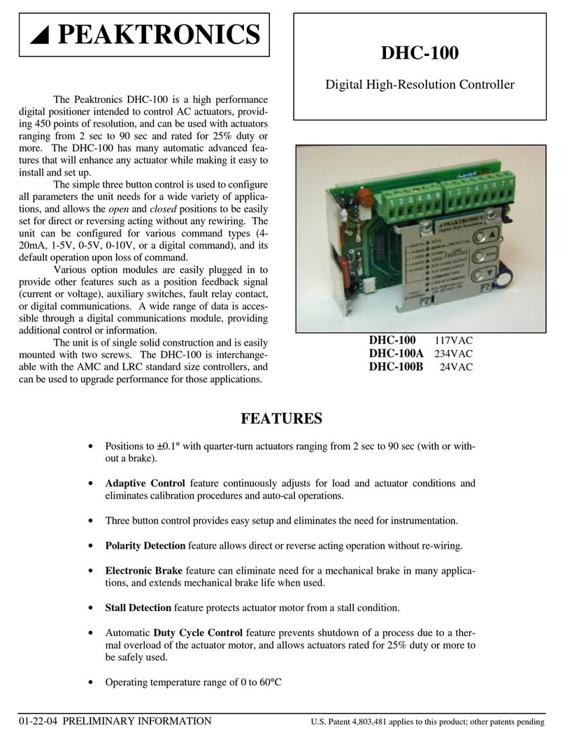
Peaktronics DHC Series User manual

TECHNICAL
MANUAL
Modbus User's Guide
DHC Series Controllers
PEAKTRONICS


2012 Peaktronics, Inc.
www.peaktronics.com
PEAKTRONICS, Inc.
1363 Anderson Clawson, MI 48017 Phone (248) 542-5640 FAX (248) 542-5643
800-161C
PEAKTRONICS
TECHNICAL MANUAL
Modbus User's Guide -
DHC Series Controllers
CONTENTS
page
SECTION I – Overview 1
System Overview
DHC Control Panel
Control Hierarchy
Modbus to PACS
Format
PACS
Parameters
Modbus Functions $03 and $06
Modbus Function $08
SECTION II - PACS
Read Only Parameters 5
Analog Command Input
Battery Voltage
Average Motor Current
Motor Current Trip Setting
Position
AlarmFlags2
Average % Duty Cycle
Maximum Deviation
Hours of Operation
Cycles of Operation
AlarmFlags
Mode
Configuration
Override Control
Serial Number
Serial No. MSB / Model Code
SECTION III - PACS
Read/Write Parameters 13
Aux Closed Position
Aux Open Position
PACS
Command Input
PACS
Control Register
PACS
Timeout Setting
PACS
Reset
User Non-volatile Memory
Unassigned Locations

CONTENTS continued
SECTION IV - Modbus Registers 18
OCM-101 PACS
Off Line Timer Value
Aux Closed Position
Aux Open Position
PACS
Command Input
PACS
Control Register
PACS
Timeout Setting
Analog Command Input
Position
Average % Duty Cycle
Maximum Deviation
Hours of Operation
Cycles of Operation
Configuration / Alarm Flags
Override Control / Mode
Serial No. MSB / Model Code
Serial Number
OCM-101 Version
Battery Voltage
Average Motor Current
Motor Current Trip Setting
Alarm Flags / Alarm Flags 2
SECTION V - APPLICATION INFORMATION 21
Bus Timing
Using a Digital Command Type
Overriding an Analog Command Type
APPENDIX A - PACS
Reference Guide 26
APPENDIX B - ASCII Conversion Table 27

1
SECTION I
Overview
The scope of this document is to provide a description of digital parameters available in a
Peaktronics DHC Series Controller, and how to access those parameters via a Modbus
connection. DHC Series Controllers covered by this manual are listed below. New models
may get added to this list; consult the latest revision of this manual for the most current list.
MODEL No. DESCRIPTION
DHC-100
Digital High-Resolution Controller, 5A 117VAC
DHC-100A
Digital High-Resolution Controller, 5A 234VAC
DHC-100B
Digital High-Resolution Controller, 5A 24VAC
DHC-100C
CE Ready Digital High Resolution Controller, 5A 117VAC
DHC-100D
CE Digital High Resolution Controller, 5A 234VAC
DHC-100E
CE Ready Digital High Resolution Controller, 5A 24VAC
DHC-200
Digital High-Resolution Solenoid Controller, 117VAC
DHC-200A
Digital High-Resolution Solenoid Controller, 234VAC
DHC-200B
Digital High-Resolution Solenoid Controller, 24VAC
DHC-200C
EMI Hardened Digital High Resolution Solenoid Controller, 117VAC
DHC-200D
EMI Hardened Digital High Resolution Solenoid Controller, 234VAC
DHC-200E
EMI Hardened Digital High Resolution Solenoid Controller, 24VAC
DHC-300
Digital High-Resolution 3-Phase Controller, 117VAC
DHC-300A
Digital High-Resolution 3-Phase Controller, 234VAC
DHC-300B
Digital High-Resolution 3-Phase Controller, 24VAC
DHC-400 DC
Digital High-Resolution Controller, 10-30VDC

2
SYSTEM OVERVIEW
The DHC Controller is a high performance digital
positioner designed to control an actuator that is usually
used in automated valve applications. The DHC has an
embedded PACS
®
Level 1 Slave port that provides digital
communications through its option module connector.
To connect to Modbus, the DHC requires an
OCM-101 Modbus Option Module. The OCM-101 acts
as a gateway from Modbus to PACS
®
(Peaktronics
Asynchronous Communications System). The OCM-101
merely plugs into the DHC controller and provides the
necessary connections for the bus. It also provides the
means for configuring the module for various bus settings
such as RTU/ASCII mode, Parity, baud rate, and node
address.
The data sheets for the DHC Controller and the
OCM-101 Modbus Option Module provide complete
details of the use, function, and setup of these devices.
Familiarity with each device may facilitate a better
understanding of the digital parameters discussed in this
manual. While this manual provides detailed examples of
PACS
®
commands that can be used to access or control the
DHC, a more comprehensive description of all PACS
®
commands can be found in "The PACS
®
Standard"
technical manual, available from Peaktronics.
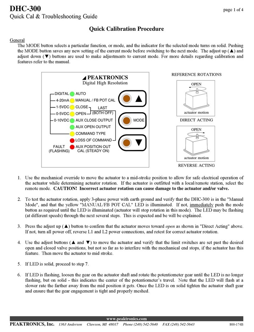
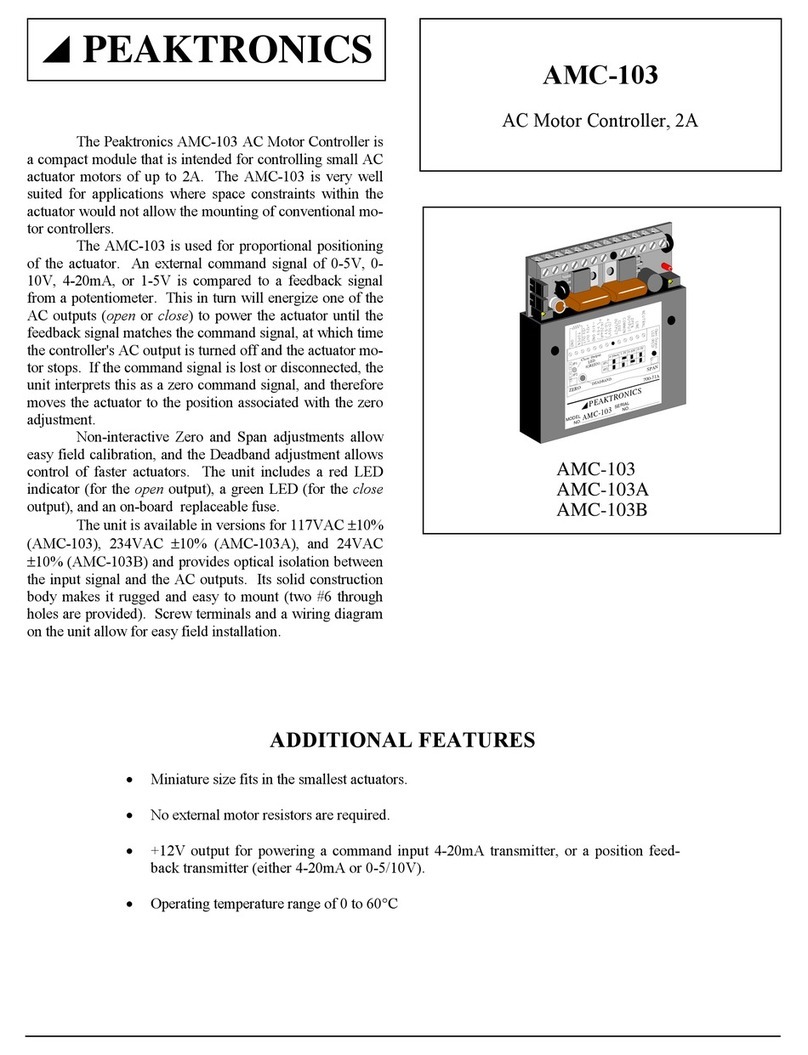
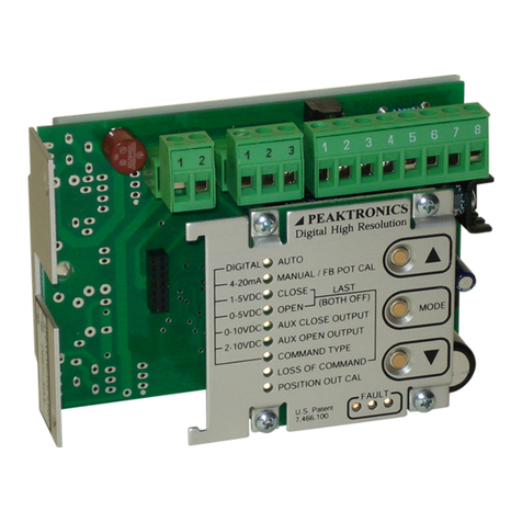
DHC CONTROL PANEL
Many of the DHC parameters relate to functions
that are set from the DHC controller's front panel. These
functions are referenced in the various discussions of the
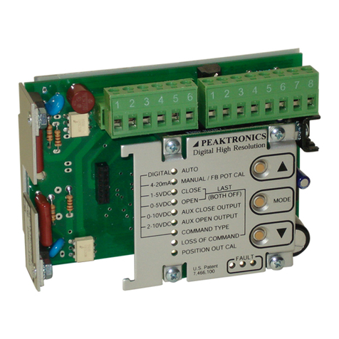
digital parameters. Figures 1 and 2 provide a visual aid of
the DHC control panel.
AUTO
MANUAL / FB POT CAL
CLOSE
OPEN
AUX CLOSE OUTPUT
AUX OPEN OUTPUT
COMMAND TYPE
LOSS OF COMMAND
DIGITAL
4-20mA
1-5VDC
0-5VDC
0-10VDC
LAST
MODE
Digital High Resolution
AUX POSITION OUTFAULT
(FLASHING) CAL (STEADY ON)
(BOTH OFF)
PEAKTRONICS
Figure 1 - DHC-100/200/300 Control Panel
AUTO
MANUAL / FB POT CAL
CLOSE
OPEN
AUX CLOSE OUTPUT
AUX OPEN OUTPUT
COMMAND TYPE
LOSS OF COMMAND
DIGITAL
4-20mA
1-5VDC
0-5VDC
0-10VDC
LAST
MODE
Digital High Resolution
(BOTH OFF)
PEAKTRONICS
POSITION OUT CAL
FAULT
2-10VDC
Figure 2 - DHC-400 Control Panel
CONTROL HIERARCHY
All DHC parameters can be monitored, or read, any
time the DHC is powered and on line. Reading parameters
does not interfere with the DHC's operation or settings.
Some parameters can be changed, or written, via the bus;
these are referred to as Read/Write Parameters. The DHC
will prohibit writing of various parameters to protect
against accidental interference with critical DHC functions
or settings; these are referred to as Read Only Parameters.
The DHC controller has a number of modes of
operation. With the exception of the AUTO mode, all the
modes are intended for either setup or trouble shooting
tasks. In those cases, it usually means that a human
operator has decided to control the actuator at the actuator
site. To prevent confusion, or even a hazard, to the human
operator, the DHC will ignore read/write parameters from
the bus that run the actuator. The automation system can
continue reading or writing such parameters, but the DHC
will not act on those parameters until the DHC is returned
to the AUTO mode. Section III discusses these parameters
in detail.
MODBUS to PACS
®
FORMAT
To convert the Modbus protocol to PACS
®
commands, the OCM-101 employs the user defined
Function Code $41 (65 decimal). The requesting Modbus
Application Data Unit (ADU) is shown below:
Address Function
($41)
PACS
®
command CRC or LRC

3
The PACS
®
command consists of one to eight hexadecimal
bytes and dictates if any data will be returned in the
responding ADU. The responding ADU is shown below:
Address Function
($41)
PACS
®
data CRC or LRC
If the PACS
®
command does not have any returning data,
the CRC or LRC bytes will immediately follow the
Function Code, $41. Otherwise, the PACS
®
data will
either be 1 byte (SING byte commands), 2 bytes (DOUB
byte commands), or 4 bytes (QUAD byte commands).
Appendix "A" provides a summary of all PACS
®
commands. Refer to "The PACS
®
Standard" manual for
complete details.
The basic structure of the PACS
®
command is
shown below:
Command
1 byte
Address
2 bytes
Data
0, 1, 2, or 4 bytes
The Command is always one byte, referred to as the
PACS
®
Code (see Appendix "A"), and dictates how many
Data bytes, if any, are required.
When required, the Address is always a two byte value
with the most significant byte following the command byte.
Some commands do not require an address, such as Indexed
commands; therefore, the data bytes, if any, will follow the
command byte.
The number of Data bytes is dictated by the command byte.
For DOUB (2 bytes) and QUAD (4 bytes) byte values, the
most significant byte is sent first. Some commands, such as
the INCR (increment) command, do not require data. Other
commands, such as the READ command, do not require
data bytes in the PACS
®
command, but rather dictates how
many bytes are to be returned by the DHC controller. Data
is returned most significant byte first.
PACS
®
PARAMETERS
While any two byte address value is valid, only a
select few correspond to parameters of significant meaning
to the user - these are referred to as the PACS
®
Parameters.
PACS
®
parameters can either be Read Only Parameters or
Read/Write Parameters. The following sections describe
the PACS
®
parameters available in the DHC Series
controllers. Table 1 provides a summary of these
parameters.
Reading locations, or addresses, not assigned to a
PACS
®
parameter will return data of unknown values.
Changing locations that are not assigned as Read/Write
Parameters are prohibited by the DHC controller and will
not alter the contents of such locations. It should be noted
that the DHC controller's internal memory pointer, which is
used for Indexed commands, will be set according to the
PACS
®
command and the provided address; even if the
address is not assigned to a parameter.
Table 1 - DHC Series PACS
®
Parameters
ADDRESS SIZE READ ONLY PARAMETERS
00B0 DOUB Analog Command Input
00B2 DOUB Battery Voltage
00B4 DOUB Average Motor Current
00B6 DOUB Motor Current Trip Setting
00B8 DOUB Position
00BD SING Alarm Flags 2
00BE DOUB Average % Duty Cycle
00C0 DOUB Maximum Deviation
00C2 QUAD Hours of Operation
00C6 QUAD Cycles of Operation
00CA SING Alarm Flags
00CB SING Mode
00CC SING Configuration
00CD SING Override Control
606C DOUB Serial No. MSB / Model Code
606E DOUB Serial Number
A
DDRESS SIZE READ
/
WRITE PARAMETERS
00D0 DOUB Aux Closed Position
00D2 DOUB Aux Open Position
00D8 DOUB PACS
®
Command Input
00ED SING PACS
®
Control Register
00EE SING PACS
®
Timeout Setting
00EF SING PACS
®
Reset
6070 DOUB
User Non-volatile Memory
6072 DOUB
6074 DOUB
6076 DOUB
6078 DOUB
607A DOUB
607C DOUB
607E DOUB
4
MODBUS FUNCTIONS $03 and $06
The DHC Series parameters can also be read using
Modbus Function $03 and written using Modbus Function
$06. Function $03 is restricted to reading a single register;
requesting more than 1 register causes an error response
with exception code $03. Table 2 provides a summary of
the available registers.
Register Addresses 0000 to 0017(hex) are
readable parameters; an error response with exception
code $03 is returned if the requested address is 0018(hex)
or higher. Register Addresses 0000 to 0005 are writeable
parameters; an error response with exception code $03 is
returned if Function $06 requests an address higher than
0005. Section IV describes the meaning of the data bytes
associated with the Modbus Function.
MODBUS FUNCTION $08
The OCM-101 supports the Modbus Diagnostics
Function ($08) and can be placed in the Listen Only Mode.
While in the Listen Only Mode, the OCM-101 will not pass
bus commands to the DHC. If the OCM-101 receives a
Broadcast command (Modbus address $00), it will pass all
bus commands it receives to the DHC, provided that the
OCM-101 is not in the Listen Only Mode.
Table 2 - Modbus Functions $03 and $06 Registers
REGISTER
NUMBER REGISTER
ADDRESS PARAMETER
1
0000
OCM-101 PACS
®
Off Line Timer Value
2
0001
Aux Closed Position
3
0002
Aux Open Position
4
0003
PACS
®
Command Input
5
0004
PACS
®
Control Register
6
0005
PACS
®
Timeout Setting
7
0006
Analog Command Input
8
0007
Position
9
0008
Average % Duty Cycle
10
0009
Maximum Deviation
11
000A
Hours of Operation (MSW)
12
000B
Hours of Operation (LSW)
13
000C
Cycles of Operation (MSW)
14
000D
Cycles of Operation (LSW)
15
000E
Configuration / Alarm Flags
16
000F
Override Control / Mode
17
0010
Serial No. MSB / Model Code
18
0011
Serial Number
19
0012
OCM-101 Version (MSW)
20
0013
OCM-101 Version (LSW)
21
0014 Battery Voltage
22
0015 Average Motor Current
23
0016 Motor Current Trip Setting
24
0017
Alarm Flags / Alarm Flags 2

5
SECTION II
PACS
®
Read Only Parameters
ANALOG COMMAND INPUT
00B0 DOUB
The DHC controller can be configured to control
an automated valve using an Analog Command Input
signal, such as 4-20mA. This parameter can be read as a
DOUB byte value as shown below:
PACS
®
Command (RD#B0):
51 00 B0
Returned Data (example):
0D 9E
The returned data is a 16 bit value (DOUB byte) ranging
from 0 to 10000 and represents a reading of 0% to 100%
open. In the example above, $0D9E (3486 decimal)
represents a value of 34.86% open. The DHC
automatically scales this parameter according to the type of
analog signal selected:
Analog 0% 100%
Input Reading Reading
4-20mA 4mA 20mA
1-5V 1V 5V
2-10V 2V 10V (DHC-400 only)
0-5V 0V 5V
0-10V 0V 10V
If the analog signal is not connected to the DHC
controller, a reading of 0% is returned. A reading of 0% is
also returned when the analog signal is less than 4mA for a
4-20mA signal, and less than 1V for a 1-5V signal. If the
analog input signal exceeds the value associated with
100%, a reading of 100% is returned. If the DHC is
configured for a Digital command type, a reading of 0% is
returned. A digital command input must come from the
bus, and can be read and written using the PACS
®
Command Input parameter (see Section III).
The command input type cannot be selected via the
bus, and must be configured at the DHC using the
COMMAND TYPE mode. However, the setting can be
read using the Configuration parameter.
BATTERY VOLTAGE
(DHC-400 only)
00B2 DOUB
The DHC-400 controller monitors the Battery
Voltage, or the DC power source, that is used to power the
unit and the actuator's motor. This parameter is a DOUB
byte value that is automatically scaled from 0 to 3200
which represents 0 to 32.00 volts. Internally, the DHC-400
monitors the battery voltage to detect when a low battery
voltage condition occurs and provides a low battery voltage
alarm (see Alarm Flags 2). In the following example,
$09A0 (2464 decimal) represents a voltage of 24.64V.

6
PACS
®
Command (RD#B2):
51 00 B2
Returned Data (example):
09 A0
AVERAGE MOTOR CURRENT
(DHC-400 only)
00B4 DOUB
The Average Motor Current parameter is a
measure of the average current drawn by the motor during
the past 3 to 4 minutes. This parameter is useful in
monitoring the drain on the DC power source; particular to
batteries, this parameter can be used to project how long a
given battery charge might last. This parameter is a DOUB
byte value that is scaled from 0 to 2500 representing 0 to
25.00A. In the following example, $009B (155 decimal)
represents a current of 1.55A.
PACS
®
Command (RD#B4):
51 00 B4
Returned Data (example):
00 9B
MOTOR CURRENT TRIP SETTING
(DHC-400 only)
00B6 DOUB
The DHC-400 features a current trip function that
can be used in place of, or in addition to, torque switches
that are commonly used in actuators. The trip current is set
by adjusting the on-board trim pot. The setting cannot be
overwritten, but can be read. The Trip Current Setting
parameter is a DOUB byte value that is scaled from 0 to
1200 representing 0 to 12.00A. In the following example,
$0140 (320 decimal) represents a current trip setting of
3.20A.
PACS
®
Command (RD#B6):
51 00 B6
Returned Data (example):
01 40
POSITION
00B8 DOUB
In order to position an automated valve to a desired
position (according to the analog or digital command
input), the DHC controller uses a feedback potentiometer to
monitor the position of the actuator's output shaft that
connects to the valve stem. This parameter is a DOUB byte
value that is automatically scaled from 0 to 10000 which
represents 0% to 100% open. In the following example,
$0D96 (3478 decimal) represents a position of 34.78%
open.
PACS
®
Command (RD#B8):
51 00 B8
Returned Data (example):
0D 96
When setting up the DHC controller, the user can
set the closed position, using the CLOSE mode, to any
point within the range of the actuator. Likewise, the open
position can be set to any desired point using the OPEN
mode. The DHC automatically scales the Position
parameter to associate 0% with the closed position, and
100% with the open position.
If the feedback potentiometer is operated outside of
its range (usually due to incorrect installation), or if it incurs
a failure (broken connection, shorted connection, etc.), the
Position parameter will either read 0% or 100%. When this
occurs, the FAULT light on the DHC controller will flash
and the outputs to the actuator are turned off. The
automation system can monitor this fault condition using
the Alarm Flags parameter.
ALARM FLAGS 2
(DHC-400 only)
00BD DOUB
The Alarm Flags 2 parameter is a SING byte
value, where each bit corresponds to one of the alarm
conditions monitored by a DHC-400 controller. These are
in addition to the alarm conditions that are monitored for
the Alarm Flags parameter. A bit value of "1" indicates
that the associated alarm condition has been detected, while
a "0" bit indicates that no alarm condition has been
detected. These alarm conditions cause a fault, where the
DHC-400 controller disables the outputs to the actuator and
sets the FAULT lights on the control panel accordingly.

7
The bit assignment for each alarm condition is shown
below:
7 6 5 4 3 2 1 0
X command out of range alarm
0 unassigned (always "0")
X motor alarm (no M1 motion)
X motor alarm (no M2 motion)
0 unassigned (always "0")
X motor current trip alarm (M1)
X motor current trip alarm (M2)
X low battery voltage alarm
In the following example, $A0 (1010 0000 binary) indicates
that a "low battery voltage alarm" and a "motor current trip
alarm (M1)" have been detected.
PACS
®
Command (RS#BD):
50 00 BD
Returned Data (example):
A0
Bit 0 - "command out of range alarm"
The DHC-400 detects when the analog command
input signal exceeds its maximum value (e.g., more
than 10V for a 2-10V command signal) and bit 0 is
set to "1" accordingly; note that the actuator will
run to 100% open before the motor is shut off.
When the analog input signal polarity is connected
backwards for a 0-5V or 0-10V command signal,
bit 0 is also set to "1"; note that the actuator will
run to 0% open before the motor is shut off. For a
4-20mA, 1-5V, or 2-10V command signal,
backward polarity is detected as a Loss of
Command and sets bit 0 of the Alarm Flags
($00CA) parameter instead.
Bit 1 - UNASSIGNED (always "0")
Bit 2 - "motor alarm (no M1 motion)"
When the DHC-400 turns on its M1 output to run
the actuator and does not detect any motion after a
period of time, bit 2 will be set to "1" if the motor
current was less than 0.5A. If the motor current
was greater than 0.5A, a motor stall is detected, and
bit 2 of the Alarm Flags ($00CA) parameter is set
to "1" instead. Whether the M1 direction is toward
open or closed depends on where those positions
have been set. When the DHC-400 is operated in
the manual mode from its control panel (see Figure
2), the ▲button turns on the M1 output.
Bit 3 - "motor alarm (no M2 motion)"
Bit 3 is set to "1" in the same manner as bit 2
except for the M2 direction. The M2 direction is
associated with the ▼button when the DHC is
operated in the manual mode.
NOTE: When bits 2 and 3 are both set to "1", this
indicates no motion detected in both directions.
The alarms can be cleared mechanically at the
actuator, but also by powering the unit down and
back up. This allows the DHC-400 to attempt
moving the actuator. A power down sequence can
also be simulated via the bus using the PACS
®
Reset parameter (see Section III).
Bit 4 - UNASSIGNED (always "0")
Bit 5 - "motor current trip alarm (M1)"
When the DHC-400 turns on its M1 output to run
the actuator and detects a motor current that
exceeds the trip current setting, bit 5 will be set to
"1". Whether the M1 direction is toward open or
closed depends on where those positions have been
set. When the DHC-400 is operated in the manual
mode from its control panel (see Figure 2), the ▲
button turns on the M1 output.
Bit 6 - "motor current trip alarm (M2)"
When the DHC-400 turns on its M2 output to run
the actuator and detects a motor current that
exceeds the trip current setting, bit 6 will be set to
"1". Whether the M2 direction is toward open or
closed depends on where those positions have been
set. When the DHC-400 is operated in the manual
mode from its control panel (see Figure 2), the ▼
button turns on the M2 output.
NOTE: When bits 5 and 6 are both set to "1", this
indicates a current trip in both directions. The
alarms can be cleared mechanically at the actuator,
but also by powering the unit down and back up.
This allows the DHC-400 to attempt moving the
actuator. A power down sequence can also be
simulated via the bus using the PACS
®
Reset
parameter (see Section III).
Bit 7 - "low battery voltage alarm"
Bit 7 is set to "1" whenever the DHC-400 detects a
battery voltage below 10VDC. While the battery
voltage is below 10VDC, communications, as well
as motor operations, are suspended, but continue
immediately after the voltage returns above
10VDC. For this reason, bit 7 remains set for 3
seconds after the battery voltage returns above
10VDC.

8
AVERAGE % DUTY CYCLE
00BE DOUB
Duty cycle is a measure of the amount of time an
actuator is turned on versus the amount of time it is turned
off. The measurement is expressed as a percentage of time
the actuator is turned on. For example, if over a 50 second
period, the actuator was turned on for a total of 10 seconds,
it is said that the percent duty cycle is 20% (10 seconds
divided by 50 seconds).
In a typical PID control application, the average
duty cycle will range from 10% to 20%. Persistent readings
above 20% duty can indicate that PID settings are changing
too fast for the process being controlled. It can also
indicate that the actuator/valve combination is not suitably
sized for the application.
To protect an electric actuator motor from
overheating, the DHC-100, 300, and 400 Series controllers
incorporate a duty control feature that intentionally reduces
the duty cycle to a safe level when they detect excessive
heating of the motor. This has the effect of slowing down
the actuator, which offsets PID signals that are changing too
fast. In this case, the reduced duty cycle is reflected in the
Average % Duty Cycle parameter.
The Average % Duty Cycle parameter represents
the duty cycle measured during the past 80 to 100 seconds.
This parameter is assigned to a DOUB byte value that
ranges from 0 to 100, representing 0% to 100% duty.
In the following example, $000D (13 decimal) represents a
duty cycle of 13%.
PACS
®
Command (RD#BE):
51 00 BE
Returned Data (example):
00 0D
Since the Average % Duty Cycle parameter is
limited to a value of 100 ($64 hexadecimal), the most
significant byte of the returned data is always zero. This
parameter can also be read as a SING byte value as shown
below:
PACS
®
Command (RS#BF):
50 00 BF
Returned Data (example):
0D
MAXIMUM DEVIATION
00C0 DOUB
While the command input signal provides the
desired position, the actual achievable position will most
often be somewhat less or more. The difference between
the actual position achieved and the desired position is
called deviation. The DHC controller automatically
determines the best performance that can be attained based
on the actuator being controlled.
The Maximum Deviation parameter provides a
measure of this performance. The parameter is a DOUB
byte value ranging from 0 to 10000 that represents 0% to
100%. In the example below, $000F (15 decimal) indicates
a maximum deviation of 0.15%. If the command input
signal is 40.00%, then the position the DHC controller can
achieve will be from 39.85% to 40.15%.
PACS
®
Command (RD#C0):
51 00 C0
Returned Data (example):
00 0F
In a typical PID application, the Maximum
Deviation parameter will be 0.50% or less, and quite
commonly will vary between 0.10% and 0.20%. When this
parameter exceeds 0.50%, the PID control algorithm will
tend to move the actuator more often which will be
reflected in the Average % Duty Cycle parameter.
HOURS OF OPERATION
00C2 QUAD
The DHC controller maintains an internal "hour
meter" which can be read as the Hours of Operation
parameter. The parameter is a QUAD byte value that
ranges from 0 to 4,294,967,295 representing the number of
hours that power has been applied to the DHC since its time
of manufacture. The parameter is set to zero at the time of
manufacture and cannot be changed or reset by the user.
The Hours of Operation parameter can be useful in
automating preventative maintenance schedules. In the
following example, $0000131C (4892 decimal) indicates
that the DHC controller has been powered for 4,892 hours.
PACS
®
Command (RQ#C2):
52 00 C2
Returned Data (example):
00 00 13 1C

9
CYCLES OF OPERATION
00C6 QUAD
While the Hours of Operation parameter can
provide a measure of how long an actuator/valve has been
in service, the wear on the mechanical components in an
actuator and valve is better measured by how often the
valve is moved. The Cycles of Operation parameter is a
cycle counter that indicates how many times the actuator
was switched from off to on by the DHC controller. The
parameter is set to zero at the time of manufacture and
cannot be changed or reset by the user.
This parameter is a QUAD byte value that ranges
from 0 to 4,294,967,295 representing the number of cycles.
In the following example, $001A5E06 (1728006 decimal)
indicates that the DHC controller turned the actuator on
1,728,006 times.
PACS
®
Command (RQ#C6):
52 00 C6
Returned Data (example):
00 1A 5E 06
ALARM FLAGS
00CA SING
The Alarm Flags parameter is a SING byte value,
where each bit corresponds to one of the alarm conditions
monitored by the DHC controller. A bit value of "1"
indicates that the associated alarm condition has been
detected, while a "0" bit indicates that no alarm condition
has been detected. The bit assignment for each alarm
condition is shown below:
7 6 5 4 3 2 1 0
X loss of command
X feedback potentiometer alarm
X motor alarm (M1 stall)
X motor alarm (M2 stall)
X open limit switch alarm
X close limit switch alarm
X aux open limit alarm
X aux close limit alarm
Bits 0-5 are alarm conditions that cause a fault, where the
DHC controller disables the outputs to the actuator. A
FAULT condition is also indicated on the DHC control
panel (see Figures 1 and 2).
In the following example, $81 (1000 0001 binary) indicates
that an "aux close limit alarm" and a "loss of command"
alarm have been detected.
PACS
®
Command (RS#CA):
50 00 CA
Returned Data (example):
81
Bit 0 - "loss of command"
When configured for a 4-20mA, 1-5V, 2-10V
(DHC-400 only), or Digital command type, the
DHC controller can detect when the command
signal has been lost and sets this bit accordingly.
For a 0-5V or 0-10V command type, a loss of
command cannot be detected and this bit will
always read "0". The DHC can also be configured
to run to the open or closed position when a "loss
of command" alarm is detected.
The DHC-100, 200, and 300 Series controllers
detect a loss of command when the analog input
signal goes below its minimum value (e.g., less
than 4mA for 4-20mA command type) or above its
maximum value (e.g., more than 20mA for a 4-
20mA command type). The DHC-400 differs in
that it detects a command out of range alarm for
signals that are above the maximum value (see
Alarm Flags 2 ($00BD) parameter).
Bit 1 - "feedback potentiometer alarm"
If the feedback potentiometer, which provides
position information to the DHC, is operated
outside of its range, bit 1 will be set to "1". The out
of range condition is detected when the
potentiometer reaches less than 5%, or more than
95%, of its resistance value. A broken or shorted
wire will cause the feedback signal to be at one of
the extremes, and therefore is detected as well.
Bit 2 - "motor alarm (M1 stall)"
When the DHC controller turns on its M1 output to
run the actuator and does not detect any motion
after a period of time, bit 2 will be set to "1". This
indicates that the DHC has detected a stall in the
M1 direction. Since the DHC-400 measures motor
current, this bit is set if the current was greater than
0.5A, otherwise bit 2 of the Alarm Flags 2
($00BD) parameter is set. Whether the M1
direction is toward open or closed depends on
where those positions have been set. When the
DHC is operated in the manual mode from its
control panel (see Figure 1), the ▲button turns on
the M1 output.

10
Bit 3 - "motor alarm (M2 stall)"
Bit 3 is set to "1" if the DHC detects a stall in the
M2 direction. The M2 direction is associated with
the ▼button when the DHC is operated in the
manual mode.
NOTE: When bits 2 and 3 are both set to "1", this
indicates a stall detected in both directions. The
alarms can be cleared mechanically at the actuator,
but also by powering the unit down and back up.
This allows the DHC to attempt moving the
actuator. A power down sequence can also be
simulated via the bus using the PACS
®
Reset
parameter (see Section III).
Bits 4 - "open limit switch alarm" (DHC-400 only)
The actuator's limit switches should be set outside
of the open and closed positions so that the DHC
controller can accurately position at 0% and 100%.
Since the DHC-400 requires the limit switches be
connected to the controller, it will detect when the
limit switch is reached and sets bit 4 to "1"
accordingly. While this causes a fault condition,
the unit flashes the OPEN indicator rather than one
of the FAULT indicators.
Bits 5 - "close limit switch alarm" (DHC-400 only)
Bit 5 performs a similar function as bit 4 for the
close limit switch. The CLOSE indicator flashes,
rather than one of the FAULT indicators, when the
close limit switch is reached.
Bit 6 - "aux open limit alarm"
Mechanical auxiliary switches are commonly
installed in actuators to provide a signal when the
actuator's position reaches a critical point before
full open. Bit 6 can be used to eliminate the need
for such a switch. The desired position can be set
using the AUX OPEN OUTPUT mode from the
DHC control panel. Alternatively, the aux open
position can be precisely set using the Aux Open
Position parameter (see Section III). Bit 6 is set to
"1" whenever the actuator's position is between the
aux open position and the open position.
Technically, this alarm is not considered a fault
condition, and the DHC flashes the AUX OPEN
OUTPUT light whenever bit 6 is "1".
Bit 7 - "aux close limit alarm"
Bit 7 performs a similar function as bit 6 for the
aux close position. The aux close position can be
set with the AUX CLOSE OUTPUT mode on the
DHC controller, or by using the Aux Closed
Position parameter (see Section III). Bit 7 is set to
"1", and the DHC flashes the AUX CLOSE
OUTPUT light, whenever the actuator's position is
between the aux close position and the closed
position.
MODE
00CB SING
The Mode parameter is a SING byte value that
indicates what mode of operation the DHC controller is in.
Since the bus cannot control the DHC outputs to the
actuator unless the DHC controller is set to the AUTO
mode, it can be useful to monitor this parameter. The
values of the Mode parameter are listed below, and are the
only values returned by the DHC controller.
decimal value DHC mode
0 AUTO
1 MANUAL
2 CLOSE
3 OPEN
4 COMMAND TYPE
5 AUX CLOSE OUTPUT
6 AUX OPEN OUTPUT
7 LOSS OF COMMAND
10 PACS
®
MANUAL
11 POSITION OUT CAL (Close)
12 POSITION OUT CAL (Open)
In the following example, $0B (11 decimal)
indicates that the DHC is in the POSITION OUT CAL
(Close) mode.
PACS
®
Command (RS#CB):
50 00 CB
Returned Data (example):
0B
DHC controllers feature an override input that
allows an operator to manual control the actuator from an
external local/remote station. When override operation is
enabled, the Mode parameter reports the mode of operation
the DHC was in prior to override control. If bit 7 of the
Override Control parameter is "0", the Mode parameter
indicates the active mode of operation. If bit 7 of the
Override Control parameter is "1", the mode of operation
indicated by the Mode parameter is not active, and the
DHC is in override operation. If a local/remote station is
used, both parameters will need to be monitored to
determine the DHC controller's mode of operation.

11
CONFIGURATION
00CC SING
The Configuration parameter is a SING byte
value, where groups of bits are assigned to various DHC
controller settings. The bit assignments are shown below:
7 6 5 4 3 2 1 0
X polarity
XXX command type setting
XX loss of command setting
XX indeterminate
In the following example, $12 (0001 0010 binary)
indicates that the DHC controller is configured for a 4-
20mA command input and a loss of command setting that
will close the actuator upon a loss of command.
PACS
®
Command (RS#CC):
50 00 CC
Returned Data (example):
12
Bit 0 - "polarity"
This bit is automatically set by the DHC
controller's polarity detection feature, and is not
meaningful to the automation system except for
advanced trouble shooting purposes. When this bit
is "0", it indicates that the DHC's M1 output drives
the actuator in a direction that corresponds to a
decreasing voltage on the DHC's feedback
potentiometer WIPER input. The M1 output is the
one that turns on with the ▲button when the DHC
controller is in the MANUAL mode. When this bit
is "1", it indicates that the M2 output (the ▼
button) corresponds to a decreasing voltage on the
WIPER input.
Bits 1, 2, & 3 - "command type setting"
These three bits indicate the command type the
DHC controller is expecting to use to position the
actuator in the AUTO mode. Only the values
shown below are returned.
3 2 1
0 0 0 Digital command (PACS
®
Command)
0 0 1 4-20mA command
0 1 0 1-5V command
0 1 1 2-10V command (DHC-400 only)
1 0 0 0-10V command
1 1 0 0-5V command
Bits 4 & 5 - "loss of command setting"
These bits indicate what action the DHC controller
will take when it detects a loss of command. Only
the values shown below are returned.
5 4
0 0
last position (DHC outputs disabled)
0 1
close (DHC moves to closed position)
1 0
open (DHC moves to open position)
Bits 6 & 7 - These bits are not used by the DHC controller
and should be ignored. Their value is unknown,
and therefore they are indeterminate.
OVERRIDE CONTROL
00CD SING
The Override Control parameter is a SING byte
value where bit 7 is "1" when override operation is enabled
by an external local/remote station. While in override
operation, the DHC controller is disabled (including the
three control panel buttons), and the local/remote station
has direct control of the DHC controller's outputs. When
bit 7 is "0", the DHC controller is in normal operation, and
the Mode parameter indicates the DHC's mode of
operation. The remaining bit assignments are shown
below.
7 6 5 4 3 2 1 0
XX local/remote function
0 0 0 0 0 unassigned (always "0")
X override status
In the following example, $82 (1000 0010 binary)
indicates that the DHC is in override operation and the
DHC output associated with the closed position is on.
PACS
®
Command (RS#CD):
50 00 CD
Returned Data (example):
82
Bits 0 & 1 - "local/remote function"
These bits are useful for trouble shooting problems
with the local/remote switches and indicate which
DHC output is turned on. Only the values shown
below are returned.
1 0
0 0
off (both outputs off)
0 1
open output on
1 0
close output on

12
Bits 2, 3, 4, 5, & 6 - UNASSIGNED (always "0")
Bit 7 - "override status"
A "1" indicates that override operation is enabled,
and a "0" indicates that the DHC is in normal
operation. When this bit is "0", the remaining bits
will also be "0".
SERIAL NUMBER
606E DOUB
The Serial Number parameter is a DOUB byte
value that represents the two least significant bytes of the
DHC controller's serial number. This parameter can only
be read using the READ DOUB byte command with direct
addressing (PACS
®
Code $51) as shown in the example
below. Any other READ command will return $FF data.
PACS
®
Command (RD#606E):
51 60 6E
Returned Data (example):
05 E3
To obtain the complete serial number, the most
significant byte of the Model Code parameter provides the
most significant byte of the serial number.
SERIAL No. MSB / MODEL CODE
606C DOUB
The Model Code parameter is a DOUB byte value
that indicates which model of DHC controller (see page 1)
is being used. This parameter can only be read using the
READ DOUB byte command with direct addressing
(PACS
®
Code $51) as shown in the example below. Any
other READ command will return $FF data.
PACS
®
Command (RD#606C):
51 60 6C
Returned Data (example):
01 02
In the previous example, the most significant byte,
$01, provides the most significant byte of the 3 byte serial
number value. The least significant byte, $02 (2 decimal),
represents the DHC model as shown in the following table.
Refer to the most recent revision of this manual for model
codes that are not shown. No model is assigned a Model
Code of $00 or $FF (255 decimal). Model code 13 ($0D) is
assigned to a custom product; consult Peaktronics, Inc. for
details.
Model Code DHC model
(decimal)
1 DHC-100
2 DHC-100A
3 DHC-100B
4 DHC-300
5 DHC-300A
6 DHC-300B
7 DHC-200
8 DHC-200A
9 DHC-200B
10 DHC-100C
11 DHC-100D
12 DHC-100E
13 DHC-100Z (custom product)
14 DHC-200C
15 DHC-200D
16 DHC-200E
17 DHC-400
Each DHC model has its own serial number
sequence, so two different model numbers could have the
same serial number. By reading both the Model Code
parameter and the Serial Number parameter, a specific
DHC controller can be identified. In the previous
examples, model code, $02, indicates a DHC-100A with
serial number 67043 ($0105E3). This combination is
unique to that specific DHC controller.
If the 3 byte serial number value reads $000000, it
could indicate that there is an internal problem with the
DHC controller. A model code of $00 or $FF (255
decimal) could also indicate an internal problem. Consult
Peaktronics, Inc. for assistance in these cases.

13
SECTION III
PACS
®
Read/Write Parameters
AUX CLOSED POSITION
00D0 DOUB
The Aux Closed Position parameter is a DOUB
byte value that represents the aux close setting associated
with the "close limit alarm" (bit 7 of the Alarm Flags
parameter described in Section II). The value ranges from
0 to 10000 and represents a setting of 0% to 100%, where
0% is the closed position and 100% is the open position. In
the following example, the parameter is changed via the bus
to $09E7 (2535 decimal), which is a setting of 25.35%.
PACS
®
Command (CD#D0,2535):
82 00 D0 09 E7
This parameter can be read (as shown below) or
written at any time and is stored in non-volatile memory
within the DHC controller. The OCM-101 returns a normal
response to a CHANGE command, only when the DHC
controller has successfully stored the value. When writing
values greater than 10000 (2710 hexadecimal), the DHC
automatically limits the value to 10000.
PACS
®
Command (RD#00D0):
51 00 D0
Returned Data (example):
09 E7
The DHC controller will set bit 7 of the Alarm
Flags parameter to "1" whenever the Position parameter
(see Section II) is less than the aux close setting. Bit 7 is set
to "0" when the Position parameter is greater than or equal
to the aux close setting plus 1%. This provides hysteresis
that prevents the alarm flag from toggling between "1" and
"0" due to random electrical or mechanical variations. In
the previous example, the parameter is set to 25.35%. Bit 7
is set to "1" when Position is 25.34% or less, and bit 7 is set
to "0" when Position is 26.35% or more.
It should be noted that the aux close position can
also be set from the DHC control panel using the AUX
CLOSE OUTPUT mode. However, setting this parameter
precisely from the DHC controller can be difficult. If a
precise setting via the bus is desired, occasionally reading
this parameter to insure that an operator has not changed the
setting may be prudent.
AUX OPEN POSITION
00D2 DOUB
The Aux Open Position parameter is used the
same way as the Aux Closed Position parameter. It is a
DOUB byte value that represents the aux open setting
associated with the "open limit alarm" (bit 6 of the Alarm
Flags parameter). Bit 6 of the Alarm Flags parameter is
set to "1" whenever the Position parameter is greater than
the aux open setting. Bit 6 is set to "0" when the Position

14
parameter is less than or equal to the aux open setting
minus 1%. The aux open position can also be set from the
DHC control panel using the AUX OPEN OUTPUT mode.
In the following example, the parameter is changed
via the bus to $1D29 (7465 decimal), which is a setting of
74.65%. Bit 6 of Alarm Flags is set to "1" when Position
is 74.66% or more, and bit 6 is set to "0" when Position is
73.65% or less.
PACS
®
Command (CD#D2,7465):
82 00 D2 1D 29
The parameter can be read as shown below:
PACS
®
Command (RD#00D2):
51 00 D2
Returned Data (example):
1D 29
PACS
®
COMMAND INPUT
00D8 DOUB
The PACS
®
Command Input parameter is a
DOUB byte value that is used to control the position of the
valve via the bus. The value ranges from 0 to 10000 and
represents 0% to 100% open. The parameter can be written
at anytime as shown in the example below. The value of
$11DF (4575 decimal) represents a command signal of
45.75% open. When writing values greater than 10000
(2710 hexadecimal), the DHC automatically limits the
value to 10000.
PACS
®
Command (CD#D8,4575):
82 00 D8 11 DF
The parameter can be read at anytime as shown below:
PACS
®
Command (RD#00D8):
51 00 D8
Returned Data (example):
11 DF
The DHC controller will use the PACS
®
Command Input parameter instead of the Analog
Command Input parameter (see Section II) when it is
configured to do so. Before the DHC uses the PACS
®
Command Input parameter, the PACS
®
Timeout Setting
parameter must be set via the bus. If the timeout setting is
zero when the PACS
®
Command Input parameter is
written to a DHC-400 controller, the DHC-400 will
automatically set the timeout value to 4 (2 seconds).
The DHC can be configured in two ways to use the
PACS
®
Command Input parameter. First, the DHC can
be configured for a Digital command type from the DHC
control panel using the COMMAND TYPE mode. In this
case, the DHC controller ignores the analog input signals
and will wait for a command from the bus, being the
PACS
®
Command Input parameter.
In the second configuration, the DHC is configured
for one of the analog command types, and the bus can
override the analog command. In this case, the PACS
®
Control Register parameter must also be configured, via
the bus, to override the analog signal.
The PACS
®
Command Input, PACS
®
Timeout
Setting, and PACS
®
Control Register parameters are not
saved in non-volatile memory. This means that the
parameters' values are lost when the DHC controller loses
power, or is reset using the PACS
®
Reset parameter.
Following a power up or reset condition, the DHC sets
these parameters to zero. Therefore, it may be desirable to
use the PACS
®
Control Register parameter to detect when
a power down condition has occurred.
PACS
®
CONTROL REGISTER
00ED SING
The PACS
®
Control Register parameter is a
SING byte value, where groups of bits are assigned to
various DHC controller functions. The bit assignments are
shown below:
7 6 5 4 3 2 1 0
X command override control
XX PACS
®
manual control
X unassigned
XX set loss of command
X unassigned
X power monitor
The parameter can be written at anytime as shown
in the following example, where $80 (1000 0000 binary)
sets bit 7 ("power monitor") to "1" and bits 0 to 6 to "0".
PACS
®
Command (CS#ED,#80):
62 00 ED 80
The parameter can be read at anytime as shown below:
PACS
®
Command (RS#00ED):
50 00 ED
Returned Data (example):
80

15
On power up, or following a reset using the
PACS
®
Reset parameter, the PACS
®
Control Register
parameter is cleared to $00. If a PACS
®
timeout occurs,
bits 0, 1, and 2 will be cleared by the DHC controller. A
PACS
®
timeout occurs when the DHC controller does not
receive a requesting ADU (which can be a broadcast
command) from the bus after a certain amount of time. The
time allowed is set using the PACS
®
Timeout Setting
parameter.
Note that the PACS
®
Timeout Setting parameter
is also cleared on power up and must be set to a non-zero
value before bits 0 to 2 can be changed. If the timeout
setting is zero when the PACS
®
Control Register
parameter is written to a DHC-400 controller, the DHC-400
will automatically set the timeout value to 4 (2 seconds) if
bit 0, 1, or 2 are set to "1".
Since bits 0 to 2 allow the bus to run the actuator,
the DHC controller must be in the AUTO mode (see
CONTROL HIERARCHY in Section I) before it acts on
these bits. The values of bits 0 to 2 are not affected if the
DHC is put in a mode other than AUTO.
Bit 0 - "command override control"
When this bit is "0", the DHC controller will use
the Analog Command Input parameter (see
Section II) to control the valve. When this bit is
"1", the DHC will use the PACS
®
Command
Input parameter to control the valve. If the DHC
is configured for a Digital command type, this bit is
essentially ignored since there is no analog
command signal. In this case, the DHC will use
the PACS
®
Command Input regardless of the
value of bit 0.
Bits 1 & 2 - "PACS
®
manual control"
These bits are used to directly control the DHC
outputs in the same way as the MANUAL mode
from the DHC control panel. The bits are assigned
as follows:
2 1
0 0
PACS
®
manual control disabled
0 1
turn on M2
1 0
turn on M1
1 1
turn off M1 and M2
When both bits are "0", manual control from the
bus is disabled. When either bit is set to "1", the
Mode parameter (see Section II) will read 10
decimal to indicate PACS
®
Manual mode. Also,
bit 0 and the command input signal (analog or
digital) are ignored, which gives "PACS
®
manual
control" priority over "command override control".
The M1 output is the one that turns on with the ▲
button when the DHC controller is in the
MANUAL mode, and the M2 output corresponds
to the ▼button. The direction the actuator moves
depends on the wiring to the actuator motor.
CAUTION! These bits turn on the DHC outputs;
power to the output is maintained until turned off
via the bus. Limit switches in the actuator will be
required to disconnect power at the mechanical
limits of the actuator. Upon reaching a limit
switch, or a mechanical limit, the DHC controller
will detect a stall which can be read using the alarm
flags parameters (see Section II).
Bits 3 & 6 - unassigned
Bits 3 and 6 are unassigned and can be set to "1" or
"0", but their values perform no function. Using
these bits is not recommended since future versions
of the DHC Series may assign these bits to other
control functions.
Bits 4 & 5 - "set loss of command"
When configured for a 4-20mA, 1-5V, 2-10V
(DHC-400 only), or Digital command type, the
DHC controller can detect when the command
signal has been lost. From the DHC control panel,
the DHC can be configured to go to close, go to
open, or turn off the outputs (last position) using
the LOSS OF COMMAND mode. Alternatively,
the DHC can be configured via the bus using bits 4
and 5 as shown below:
5 4
0 1
last position (both outputs off)
1 0
close
1 1
open
These bits will always read zero; to read the
setting, use the Configuration parameter (see
Section II). Setting both bits to "0" has no affect,
and the previous setting remains. The setting is
saved in non-volatile memory, so the setting is
retained until it is changed from the DHC control
panel or via the bus.
Bit 7 - "power monitor"
This bit is set to "0" when the DHC powers up, or
is reset using the PACS
®
Reset parameter. This bit
can only be set to "1" via the bus. After setting this
bit to "1", the bit can be monitored to detect that the
DHC controller experienced a power loss. This is
particularly useful if the bus is being used to
control the DHC outputs - see PACS
®
Command
Input and PACS
®
Timeout Setting parameters.
Since the PACS
®
Control Register parameter is
divided into groups of bits, setting particular bits without
affecting others can be more effectively done using the

16
PACS
®
logic commands. The OR command can be used to
set specific bits to "1", while the AND command can be
used to clear specific bits to "0". The EX OR (exclusive-or)
command can be used to toggle specific bits between "0"
and "1". In the following example, the OR command is
used to set bit 7, while leaving bits 0 to 6 unchanged.
PACS
®
Command (ORS#ED,#80):
6A 00 ED 80
PACS
®
TIMEOUT SETTING
00EE SING
The PACS
®
Timeout Setting parameter is a SING
byte value, where all values from $00 to $FF are valid. The
value of the parameter represents time in 0.5 second
increments. For example, a value of $14 (20 decimal)
represents 10 seconds. If a PACS
®
command is not
received before this time expires (referred to as a PACS
®
timeout), the DHC controller will clear bits 0, 1, and 2 of
the PACS
®
Control Register parameter. This has the
effect of disabling bus control of the DHC outputs.
The DHC uses a PACS
®
timeout to detect a loss of
command when it is configured for a Digital command
type. In this case, bit 0 of the Alarm Flags parameter (see
Section II) is set to "1", and the DHC outputs are controlled
according to the "loss of command setting" (see Con-
figuration parameter in Section II).
Note that the OCM-101 Modbus Option Module
supports other Modbus functions. The OCM-101 only
sends PACS
®
commands to the DHC in response to
Function Code $41 (PACS
®
Function). Broadcast
commands (node 0) with the PACS
®
Function are
processed as normal; however, the OCM-101 will not send
a responding ADU.
The PACS
®
Timeout Setting parameter can be
written at anytime as shown in the example below:
PACS
®
Command (CS#EE,20):
62 00 EE 14
The parameter can be read at anytime as shown below:
PACS
®
Command (RS#00EE):
50 00 EE
Returned Data (example):
14
PACS
®
RESET
00EF SING
The PACS
®
Reset parameter is a SING byte value
that is used to force a DHC controller reset. This has the
same effect as powering the DHC off and then on. To reset
the DHC controller via the bus, write a value of $FF to this
parameter as shown in the following example. Reading this
parameter returns an unknown value and has no significant
meaning to the user.
PACS
®
Command (CS#EF,#FF):
62 00 EF FF
USER NON-VOLATILE MEMORY
6070 DOUB
6072 DOUB
6074 DOUB
6076 DOUB
6078 DOUB
607A DOUB
607C DOUB
607E DOUB
This group of DOUB byte values provides 16 bytes
of non-volatile memory that may be used by the user for
any purpose. The initial values of these locations are
cleared to zero at the time of manufacture. Writing these
locations can only be done using the CHANGE DOUB byte
command with direct addressing (PACS
®
Code $82) as
shown in the example below. Using any other writing
command will result in no operation.
PACS
®
Command (CD#6070,#03E8):
82 60 70 03 E8
These locations can only be read using the READ
DOUB byte command with direct addressing (PACS
®
Code $51) as shown below. Any other READ command
will return $FF data.
PACS
®
Command (RD#6070):
51 60 70
Returned Data (example):
03 E8
This manual suits for next models
16
Table of contents
Other Peaktronics Controllers manuals

Peaktronics
Peaktronics DHC-300 User manual

Peaktronics
Peaktronics DHC-301 User manual

Peaktronics
Peaktronics DHC-300A User manual

Peaktronics
Peaktronics DHC-100 User manual

Peaktronics
Peaktronics DHC-301 User manual

Peaktronics
Peaktronics AMC-103 User manual

Peaktronics
Peaktronics DHC-100 User manual

Peaktronics
Peaktronics DHC-400 User manual