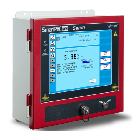
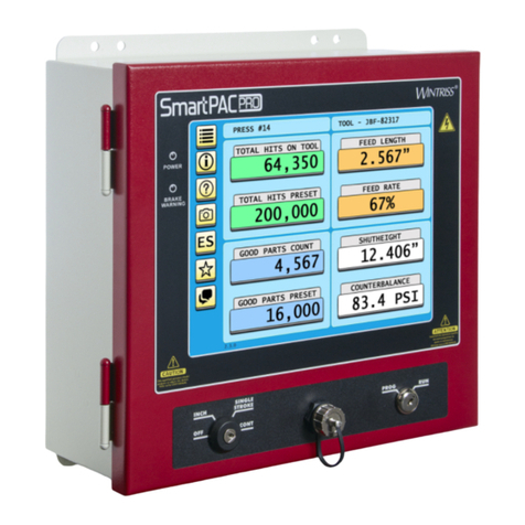
Wintriss SmartPAC2 User manual

SmartPAC 2
®
Wintriss Press Automation Control
includes optional DiPro PAC and ProCam PAC
1126700
Rev. F ctober 2014
UserUserUser
ManualManualManual
User
Manual
Tech Support Hotline 800-586-8324 8-5 EST
www.wintriss.com
®
®®
®
®
Wintriss Controls Group, LLC
100 Discovery Way
Unit 110
Acton MA 01720 USA
Phone (800) 586 8324
Fax (978) 263 2048
PRINTED IN USA DA70070

Changes for Revision F of the
SmartPAC 2 User Manual (1126700)
This revision of the SmartPAC 2 user manual covers SmartPAC 2 software version 12.73 and
higher. The changes include:
•Added to the cover of the installation manual the URL and QR code user needs to
download the user manual

Thank you for purchasing a Wintriss Product. We appreciate your business and want to do whatever
we can to ensure your satisfaction. Wintriss products are built to stay on the job day after day, and are
backed by an ironclad guarantee, international standards approvals, and unbeatable support.
Whenever you need assistance or service, we back all our products with excellent spare parts
inventories, training programs, and prompt repair service. We would like to share with you a list of
service options–probably the largest number of service options offered in the industry.
• Technical Assistance
We offer a toll-free line for technical assistance. Call our Wintriss Technical Support Hotline at
1-800-586-TECH (8324) should you have any questions about your equipment. Our technical
staff is ready to assist you Monday through Friday, 8 a.m. to 5 p.m. EST. In many cases our
experienced technical staff can resolve your inquiry right over the phone.
• Return Authorization
Please call our “800” number for a return authorization (RMA) number to return a product for
repair. Returned goods must arrive freight prepaid. In order to process your return quickly, we ask
that you provide us with the following pertinent information when you call: purchase order
number, shipping address, contact name and telephone number, and product type. The assigned
RMA number should appear on all packages returned to Wintriss Controls Group to ensure prompt
service.
At the time of requesting an RMA, you will be quoted a flat-rate repair price for the product you
are returning. We ask that you either fax us a PO for that amount or enclose the PO with the
returned item. This will enable us to ship the item back to you as soon as the repair has been
completed. If the item cannot be repaired or there are additional charges, you will be contacted for
approval.
Please be sure to carefully pack all returned items and ship to our Acton, MA location.
• Expedited Repair Program
Rush service providing 48 hour turnaround is available for most products upon request. An
Expedite Fee will be applied to our standard repair rate.
• Board Exchange Program
If your needs are urgent, you can take advantage of our Board Exchange (EX) program. Call our
“800” number between 8 a.m. and 5 p.m. EST and we will send a replacement to you overnight. A
fee does apply to this service. Contact Wintriss Technical Support at 800-586-8324 for details.
• Service Center
Our Service Center for product service is located at our headquarters in Acton MA. If your
equipment requires repair, please contact us at 800-586-8324 to obtain a return authorization
number.
Nationwide field service is also available. Contact the Wintriss Technical Support group at
800-586-8324.
• Product Training
We also offer both product training and maintenance/troubleshooting courses at our Acton, MA
and Chicago-area facilities. On-site training is available from the factory or through your local
Wintriss representative.
• Restocking Charge
Returned goods are subject to a 20% restocking charge if returned for credit. The minimum charge
is $50, not to exceed $250 per item.
Whatever the product, we are committed to satisfying you with innovative engineering, quality
construction, reliable performance, and ongoing, helpful support. Call us whenever you need
assistance.

Table of Contents i
Table of Contents
Chapter 1. Introduction to SmartPAC 2 . . . . . . . . . . . . . . . . . . . .1-1
SmartPAC 2 Standard Features . . . . . . . . . . . . . . . . . . . . . . . . . . . . . . . . . . . . . .1-1
SmartPAC 2 Options . . . . . . . . . . . . . . . . . . . . . . . . . . . . . . . . . . . . . . . . . . . . . .1-2
SmartPAC 2 Front Panel . . . . . . . . . . . . . . . . . . . . . . . . . . . . . . . . . . . . . . . . . . .1-2
Resolver-based Operation . . . . . . . . . . . . . . . . . . . . . . . . . . . . . . . . . . . . . . . . . .1-4
SmartPAC 2 Settings. . . . . . . . . . . . . . . . . . . . . . . . . . . . . . . . . . . . . . . . . . . . . .1-4
Sensors Available for DiProPAC. . . . . . . . . . . . . . . . . . . . . . . . . . . . . . . . . . . . .1-5
ProCamPAC Programmable Cams . . . . . . . . . . . . . . . . . . . . . . . . . . . . . . . . . . .1-6
SmartPAC 2’s Three Modes of Operation. . . . . . . . . . . . . . . . . . . . . . . . . . . . . .1-6
SmartPAC 2 Specifications . . . . . . . . . . . . . . . . . . . . . . . . . . . . . . . . . . . . . . . . .1-7
Chapter 2. Installing SmartPAC 2. . . . . . . . . . . . . . . . . . . . . . . . .2-1
Before You Start . . . . . . . . . . . . . . . . . . . . . . . . . . . . . . . . . . . . . . . . . . . . . . . . .2-2
Installation Guidelines. . . . . . . . . . . . . . . . . . . . . . . . . . . . . . . . . . . . . . . . . . . . .2-3
Connecting Wires to Terminal Block Connectors. . . . . . . . . . . . . . . . . . . . . . . .2-5
Terminating Cable Shields . . . . . . . . . . . . . . . . . . . . . . . . . . . . . . . . . . . . . . . . .2-5
Checking the Press . . . . . . . . . . . . . . . . . . . . . . . . . . . . . . . . . . . . . . . . . . . . . . .2-6
Mounting the SmartPAC 2 Control Enclosure . . . . . . . . . . . . . . . . . . . . . . . . . .2-7
Installing SmartPAC 2 as a Panel Mount . . . . . . . . . . . . . . . . . . . . . . . . . . . . . .2-8
Installing the Resolver. . . . . . . . . . . . . . . . . . . . . . . . . . . . . . . . . . . . . . . . . . . .2-10
Mounting the Resolver . . . . . . . . . . . . . . . . . . . . . . . . . . . . . . . . . . . . . . . . . . . . . 2-11
Wiring the Resolver. . . . . . . . . . . . . . . . . . . . . . . . . . . . . . . . . . . . . . . . . . . . . . . . 2-12
Connecting AC Wiring . . . . . . . . . . . . . . . . . . . . . . . . . . . . . . . . . . . . . . . . . . .2-14
Connecting Stop Circuits and Input Check Circuit. . . . . . . . . . . . . . . . . . . . . .2-15
Making Wiring Connections . . . . . . . . . . . . . . . . . . . . . . . . . . . . . . . . . . . . . . . . . 2-16
Setting the Input Check Voltage Switch . . . . . . . . . . . . . . . . . . . . . . . . . . . . . . . . 2-16
Connecting to Network . . . . . . . . . . . . . . . . . . . . . . . . . . . . . . . . . . . . . . . . . . .2-17
Adding or Upgrading DiProPAC or ProCamPAC. . . . . . . . . . . . . . . . . . . . . . .2-18
Replacing an Existing Board . . . . . . . . . . . . . . . . . . . . . . . . . . . . . . . . . . . . . . . . . 2-18
Installing a New Board . . . . . . . . . . . . . . . . . . . . . . . . . . . . . . . . . . . . . . . . . . . . . 2-21
Connecting DiPro Sensor Interface to SmartPAC 2 . . . . . . . . . . . . . . . . . . . . .2-22
Connecting Programmable Cam Channels . . . . . . . . . . . . . . . . . . . . . . . . . . . .2-25
Wiring Setup Mode Circuit. . . . . . . . . . . . . . . . . . . . . . . . . . . . . . . . . . . . . . . .2-31
Wiring a Remote Reset Switch (Optional) . . . . . . . . . . . . . . . . . . . . . . . . . . . .2-31
Wiring a Sensor-Disabled Output (Optional) . . . . . . . . . . . . . . . . . . . . . . . . . .2-31
Wiring the ProCamPAC Output with Your Mechanical Top Stop Cam Switch
(Optional) . . . . . . . . . . . . . . . . . . . . . . . . . . . . . . . . . . . . . . . . . . . . . . . . . . . . .2-32
Turning on Power to SmartPAC 2. . . . . . . . . . . . . . . . . . . . . . . . . . . . . . . . . . .2-33
Verifying Installation of DiProPAC and ProCamPAC . . . . . . . . . . . . . . . . . . .2-34

1126700 SmartPAC 2 User Manual
ii Table of Contents
Zeroing the Resolver . . . . . . . . . . . . . . . . . . . . . . . . . . . . . . . . . . . . . . . . . . . . 2-35
Moving the Ram to Top Dead Center (TDC). . . . . . . . . . . . . . . . . . . . . . . . . . . . .2-36
Setting the Resolver Zero Position . . . . . . . . . . . . . . . . . . . . . . . . . . . . . . . . . . . . .2-36
Installing the Position Sensor (Optional). . . . . . . . . . . . . . . . . . . . . . . . . . . . . 2-37
Setting Up High Speed Version of SmartPAC 2 (Optional) . . . . . . . . . . . . . . 2-41
Final Checkout. . . . . . . . . . . . . . . . . . . . . . . . . . . . . . . . . . . . . . . . . . . . . . . . . 2-41
Set Up a “Test” Tool . . . . . . . . . . . . . . . . . . . . . . . . . . . . . . . . . . . . . . . . . . . . . . . .2-41
Check and Set Direction of Rotation of Resolver. . . . . . . . . . . . . . . . . . . . . . . . . .2-42
Check for Position Sensor (If Installed) Error Messages . . . . . . . . . . . . . . . . . . . .2-42
Check the Top-stop Circuit. . . . . . . . . . . . . . . . . . . . . . . . . . . . . . . . . . . . . . . . . . .2-42
Check the Emergency-stop Circuit. . . . . . . . . . . . . . . . . . . . . . . . . . . . . . . . . . . . .2-42
Check Cam Channels (ProCamPAC Only). . . . . . . . . . . . . . . . . . . . . . . . . . . . . . .2-42
Test Complete . . . . . . . . . . . . . . . . . . . . . . . . . . . . . . . . . . . . . . . . . . . . . . . . . . . . .2-43
What Next? . . . . . . . . . . . . . . . . . . . . . . . . . . . . . . . . . . . . . . . . . . . . . . . . . . . 2-43
Wiring Tables for SmartPAC 2 Options. . . . . . . . . . . . . . . . . . . . . . . . . . . . . . 2-43
Chapter 3. SmartPAC 2 Keyboard, Displays and Operating
Modes . . . . . . . . . . . . . . . . . . . . . . . . . . . . . . . . . . . . . 3-1
Comparing SmartPAC 2 with Original SmartPAC . . . . . . . . . . . . . . . . . . . . . . 3-2
SmartPAC 2 Keyboard. . . . . . . . . . . . . . . . . . . . . . . . . . . . . . . . . . . . . . . . . . . . 3-3
Number Keys . . . . . . . . . . . . . . . . . . . . . . . . . . . . . . . . . . . . . . . . . . . . . . . . . . . . . .3-3
CLEAR Key . . . . . . . . . . . . . . . . . . . . . . . . . . . . . . . . . . . . . . . . . . . . . . . . . . . . . . .3-4
Cursor Keys . . . . . . . . . . . . . . . . . . . . . . . . . . . . . . . . . . . . . . . . . . . . . . . . . . . . . . .3-5
HELP Key. . . . . . . . . . . . . . . . . . . . . . . . . . . . . . . . . . . . . . . . . . . . . . . . . . . . . . . . .3-9
ENTER Key . . . . . . . . . . . . . . . . . . . . . . . . . . . . . . . . . . . . . . . . . . . . . . . . . . . . . . .3-9
RESET Key. . . . . . . . . . . . . . . . . . . . . . . . . . . . . . . . . . . . . . . . . . . . . . . . . . . . . . .3-10
Program/Run Key Switch. . . . . . . . . . . . . . . . . . . . . . . . . . . . . . . . . . . . . . . . . . . .3-10
Function Keys. . . . . . . . . . . . . . . . . . . . . . . . . . . . . . . . . . . . . . . . . . . . . . . . . . . . .3-11
Hot Keys. . . . . . . . . . . . . . . . . . . . . . . . . . . . . . . . . . . . . . . . . . . . . . . . . . . . . . . . . 3-11
SmartPAC 2 Display Layout in Run Mode . . . . . . . . . . . . . . . . . . . . . . . . . . . 3-12
Selecting an Item on a Display . . . . . . . . . . . . . . . . . . . . . . . . . . . . . . . . . . . . 3-13
SmartPAC 2 Operating Modes. . . . . . . . . . . . . . . . . . . . . . . . . . . . . . . . . . . . . 3-14
Initialization Mode. . . . . . . . . . . . . . . . . . . . . . . . . . . . . . . . . . . . . . . . . . . . . . 3-16
Program Mode . . . . . . . . . . . . . . . . . . . . . . . . . . . . . . . . . . . . . . . . . . . . . . . . . 3-18
Run Mode. . . . . . . . . . . . . . . . . . . . . . . . . . . . . . . . . . . . . . . . . . . . . . . . . . . . . 3-20
Screen Capture. . . . . . . . . . . . . . . . . . . . . . . . . . . . . . . . . . . . . . . . . . . . . . . . . 3-22
Screen Capture in SmartPAC 2 Main Versions Earlier than V 5.3.1 . . . . . . . . . . .3-22
Screen Capture in SmartPAC 2 Main Versions V 5.3.1 and Later . . . . . . . . . . . . .3-24
Chapter 4. SmartPAC 2 Initialization Mode . . . . . . . . . . . . . . . . 4-1
Entering and Exiting Initialization Mode . . . . . . . . . . . . . . . . . . . . . . . . . . . . . 4-1
RESOLVER ZERO . . . . . . . . . . . . . . . . . . . . . . . . . . . . . . . . . . . . . . . . . . . . . . 4-2

SmartPAC 2 User Manual 1126700
Table of Contents iii
POSITION SENSOR . . . . . . . . . . . . . . . . . . . . . . . . . . . . . . . . . . . . . . . . . . . . .4-3
Position Sensor Mode . . . . . . . . . . . . . . . . . . . . . . . . . . . . . . . . . . . . . . . . . . . . . . . 4-3
Resolver Motion Mode (Normal Motion – Link Motion). . . . . . . . . . . . . . . . . . . . 4-4
Angle Wheel Rotation (Clockwise – Counterclockwise) . . . . . . . . . . . . . . . . . . . . 4-4
Tool Number Mode . . . . . . . . . . . . . . . . . . . . . . . . . . . . . . . . . . . . . . . . . . . . . . . . . 4-4
Counter Setup Mode . . . . . . . . . . . . . . . . . . . . . . . . . . . . . . . . . . . . . . . . . . . . . . . . 4-6
Counter Increment Mode. . . . . . . . . . . . . . . . . . . . . . . . . . . . . . . . . . . . . . . . . . . . . 4-6
INSTALLED OPTIONS . . . . . . . . . . . . . . . . . . . . . . . . . . . . . . . . . . . . . . . . . . .4-7
PRESS NAME . . . . . . . . . . . . . . . . . . . . . . . . . . . . . . . . . . . . . . . . . . . . . . . . . .4-8
SET BRAKE MONITOR . . . . . . . . . . . . . . . . . . . . . . . . . . . . . . . . . . . . . . . . . .4-8
Calculating the Stop Time Limit . . . . . . . . . . . . . . . . . . . . . . . . . . . . . . . . . . . . . . . 4-9
Setting Stop Time and Start Time Limits . . . . . . . . . . . . . . . . . . . . . . . . . . . . . . . 4-10
SELECT CAM NAMES (Optional) . . . . . . . . . . . . . . . . . . . . . . . . . . . . . . . . .4-10
AUTO ADVANCE and Slow RPM (Optional). . . . . . . . . . . . . . . . . . . . . . . . .4-12
Calculating the Auto Advance Constant . . . . . . . . . . . . . . . . . . . . . . . . . . . . . . . . 4-14
Setting Auto Advance Constants and Slow RPM . . . . . . . . . . . . . . . . . . . . . . . . . 4-14
SET GLOBAL CAMS (Optional). . . . . . . . . . . . . . . . . . . . . . . . . . . . . . . . . . .4-15
CUSTOM SENSOR NAMES (Optional) . . . . . . . . . . . . . . . . . . . . . . . . . . . . .4-17
SENSOR ENABLE MODE (Optional) . . . . . . . . . . . . . . . . . . . . . . . . . . . . . .4-18
Selecting Sensor Enable Mode . . . . . . . . . . . . . . . . . . . . . . . . . . . . . . . . . . . . . . . 4-19
Enabling Setup Mode . . . . . . . . . . . . . . . . . . . . . . . . . . . . . . . . . . . . . . . . . . . . . . 4-20
TOOL INFORMATION . . . . . . . . . . . . . . . . . . . . . . . . . . . . . . . . . . . . . . . . . .4-20
SECURITY ACCESS . . . . . . . . . . . . . . . . . . . . . . . . . . . . . . . . . . . . . . . . . . . .4-24
Setting Security Access. . . . . . . . . . . . . . . . . . . . . . . . . . . . . . . . . . . . . . . . . . . . . 4-27
Changing Passwords . . . . . . . . . . . . . . . . . . . . . . . . . . . . . . . . . . . . . . . . . . . . . . . 4-28
BACKUP/RESTORE . . . . . . . . . . . . . . . . . . . . . . . . . . . . . . . . . . . . . . . . . . . .4-29
Backing Up Tools to a USB Disk . . . . . . . . . . . . . . . . . . . . . . . . . . . . . . . . . . . . . 4-30
Restoring Tools from a USB Disk. . . . . . . . . . . . . . . . . . . . . . . . . . . . . . . . . . . . . 4-32
SETUP DATA COMMS (Optional) . . . . . . . . . . . . . . . . . . . . . . . . . . . . . . . . .4-33
SETUP NETWORK . . . . . . . . . . . . . . . . . . . . . . . . . . . . . . . . . . . . . . . . . . . . .4-34
E-MAIL FUNCTION . . . . . . . . . . . . . . . . . . . . . . . . . . . . . . . . . . . . . . . . . . . . . . 4-34
SMARTVIEW FUNCTION . . . . . . . . . . . . . . . . . . . . . . . . . . . . . . . . . . . . . . . . . 4-35
SETUP E-MAIL . . . . . . . . . . . . . . . . . . . . . . . . . . . . . . . . . . . . . . . . . . . . . . . . . . 4-35
CHANGE NETWORK SETTINGS . . . . . . . . . . . . . . . . . . . . . . . . . . . . . . . . . . . 4-37
PRESS TYPE . . . . . . . . . . . . . . . . . . . . . . . . . . . . . . . . . . . . . . . . . . . . . . . . . . . . 4-38
DIAGNOSTICS . . . . . . . . . . . . . . . . . . . . . . . . . . . . . . . . . . . . . . . . . . . . . . . .4-38
COMMUNICATIONS. . . . . . . . . . . . . . . . . . . . . . . . . . . . . . . . . . . . . . . . . . . . . . 4-39
SET CLOCK . . . . . . . . . . . . . . . . . . . . . . . . . . . . . . . . . . . . . . . . . . . . . . . . . . . . . 4-41
SAVE TO USB DISK . . . . . . . . . . . . . . . . . . . . . . . . . . . . . . . . . . . . . . . . . . . . . . 4-42
UPDATE FIRMWARE . . . . . . . . . . . . . . . . . . . . . . . . . . . . . . . . . . . . . . . . . . . . . 4-42
Using SmartPAC 2 with a Link-motion Press. . . . . . . . . . . . . . . . . . . . . . . . . .4-42
Setting Link Motion. . . . . . . . . . . . . . . . . . . . . . . . . . . . . . . . . . . . . . . . . . . . . . . . 4-43
Using a ServoFeed Interface with Link Motion . . . . . . . . . . . . . . . . . . . . . . . . . . 4-43
Using a Computer Keyboard to Enter Names. . . . . . . . . . . . . . . . . . . . . . . . . .4-45

1126700 SmartPAC 2 User Manual
iv Table of Contents
Chapter 5. SmartPAC 2 Program Mode . . . . . . . . . . . . . . . . . . . 5-1
Entering and Exiting Program Mode. . . . . . . . . . . . . . . . . . . . . . . . . . . . . . . . . 5-1
TOOL MANAGER . . . . . . . . . . . . . . . . . . . . . . . . . . . . . . . . . . . . . . . . . . . . . . 5-2
Creating a New Tool. . . . . . . . . . . . . . . . . . . . . . . . . . . . . . . . . . . . . . . . . . . . . . . . .5-3
Copying an Existing Tool . . . . . . . . . . . . . . . . . . . . . . . . . . . . . . . . . . . . . . . . . . . . .5-4
Copying Tool Template to a New Tool. . . . . . . . . . . . . . . . . . . . . . . . . . . . . . . . . . .5-5
Loading a Tool . . . . . . . . . . . . . . . . . . . . . . . . . . . . . . . . . . . . . . . . . . . . . . . . . . . . .5-5
Changing Settings for a Loaded Tool . . . . . . . . . . . . . . . . . . . . . . . . . . . . . . . . . . . .5-6
Deleting a Tool . . . . . . . . . . . . . . . . . . . . . . . . . . . . . . . . . . . . . . . . . . . . . . . . . . . . .5-7
Tool Program Menu. . . . . . . . . . . . . . . . . . . . . . . . . . . . . . . . . . . . . . . . . . . . . . 5-8
TOOL NAME or TOOL ID. . . . . . . . . . . . . . . . . . . . . . . . . . . . . . . . . . . . . . . . 5-8
COUNTERS . . . . . . . . . . . . . . . . . . . . . . . . . . . . . . . . . . . . . . . . . . . . . . . . . . . 5-9
Setting Preset Values. . . . . . . . . . . . . . . . . . . . . . . . . . . . . . . . . . . . . . . . . . . . . . . . 5-11
Changing Count Values . . . . . . . . . . . . . . . . . . . . . . . . . . . . . . . . . . . . . . . . . . . . . 5-11
Clearing the Total Hits Counter . . . . . . . . . . . . . . . . . . . . . . . . . . . . . . . . . . . . . . .5-12
Setting Batch Counter Output and Increment Modes. . . . . . . . . . . . . . . . . . . . . . .5-13
Setting Counter Increment Angle . . . . . . . . . . . . . . . . . . . . . . . . . . . . . . . . . . . . . .5-14
Setting Parts per Stroke or Strokes per Part . . . . . . . . . . . . . . . . . . . . . . . . . . . . . .5-14
Setting Batch Pre-Load Counts. . . . . . . . . . . . . . . . . . . . . . . . . . . . . . . . . . . . . . . .5-15
DIE PROTECTION (Optional) . . . . . . . . . . . . . . . . . . . . . . . . . . . . . . . . . . . . 5-16
Understanding Sensor Terminology . . . . . . . . . . . . . . . . . . . . . . . . . . . . . . . . . . . .5-16
Programming Sensor Settings. . . . . . . . . . . . . . . . . . . . . . . . . . . . . . . . . . . . . . . . .5-20
Programming DiProPAC 32 Sensors . . . . . . . . . . . . . . . . . . . . . . . . . . . . . . . . . . .5-31
CAM SWITCH (Optional) . . . . . . . . . . . . . . . . . . . . . . . . . . . . . . . . . . . . . . . 5-37
Selecting a Cam Channel . . . . . . . . . . . . . . . . . . . . . . . . . . . . . . . . . . . . . . . . . . . .5-38
Making an ON/OFF Setting . . . . . . . . . . . . . . . . . . . . . . . . . . . . . . . . . . . . . . . . . .5-39
Setting Multiple ON/OFF Cycles . . . . . . . . . . . . . . . . . . . . . . . . . . . . . . . . . . . . . .5-40
Making a Timed Output Setting . . . . . . . . . . . . . . . . . . . . . . . . . . . . . . . . . . . . . . .5-42
Making an Auto Advance Setting. . . . . . . . . . . . . . . . . . . . . . . . . . . . . . . . . . . . . .5-44
Setting DSV ON Channel Timing . . . . . . . . . . . . . . . . . . . . . . . . . . . . . . . . . . . . .5-45
Deleting Channel Settings . . . . . . . . . . . . . . . . . . . . . . . . . . . . . . . . . . . . . . . . . . .5-46
Viewing the Cam Summary . . . . . . . . . . . . . . . . . . . . . . . . . . . . . . . . . . . . . . . . . .5-46
Viewing Global Cams. . . . . . . . . . . . . . . . . . . . . . . . . . . . . . . . . . . . . . . . . . . . . . .5-47
PRESS SPEED. . . . . . . . . . . . . . . . . . . . . . . . . . . . . . . . . . . . . . . . . . . . . . . . . 5-48
TOOL INFORMATION . . . . . . . . . . . . . . . . . . . . . . . . . . . . . . . . . . . . . . . . . 5-49
SENSOR ENABLE/DISABLE & STATUS (Optional) . . . . . . . . . . . . . . . . . 5-51
Viewing Sensor Status . . . . . . . . . . . . . . . . . . . . . . . . . . . . . . . . . . . . . . . . . . . . . .5-51
Enabling or Disabling All Sensors . . . . . . . . . . . . . . . . . . . . . . . . . . . . . . . . . . . . .5-52
Turning a Sensor Off or On . . . . . . . . . . . . . . . . . . . . . . . . . . . . . . . . . . . . . . . . . .5-52
Chapter 6. SmartPAC 2 Run Mode . . . . . . . . . . . . . . . . . . . . . . . 6-1
Entering and Exiting Run Mode . . . . . . . . . . . . . . . . . . . . . . . . . . . . . . . . . . . . 6-2
Loading a Tool. . . . . . . . . . . . . . . . . . . . . . . . . . . . . . . . . . . . . . . . . . . . . . . . . . 6-2
Programming Hot Keys . . . . . . . . . . . . . . . . . . . . . . . . . . . . . . . . . . . . . . . . . . . 6-3
Settings Locked, or Password Required . . . . . . . . . . . . . . . . . . . . . . . . . . . . . . 6-4

SmartPAC 2 User Manual 1126700
Table of Contents v
Displaying Multiple Faults . . . . . . . . . . . . . . . . . . . . . . . . . . . . . . . . . . . . . . . . .6-5
DISABLE (ENABLE) SENSORS . . . . . . . . . . . . . . . . . . . . . . . . . . . . . . . . . . .6-5
COUNTERS . . . . . . . . . . . . . . . . . . . . . . . . . . . . . . . . . . . . . . . . . . . . . . . . . . . .6-7
DIE PROTECTION (Optional). . . . . . . . . . . . . . . . . . . . . . . . . . . . . . . . . . . . . .6-9
Adjusting the Ready Signal for Green Sensors . . . . . . . . . . . . . . . . . . . . . . . . . . . 6-10
Adjusting the Stroke Preset for Green Special Sensors. . . . . . . . . . . . . . . . . . . . . 6-12
Viewing the Sensor Summary . . . . . . . . . . . . . . . . . . . . . . . . . . . . . . . . . . . . . . . . 6-12
Viewing Sensor Status. . . . . . . . . . . . . . . . . . . . . . . . . . . . . . . . . . . . . . . . . . . . . . 6-12
Adjusting DiProPAC 32 Sensors. . . . . . . . . . . . . . . . . . . . . . . . . . . . . . . . . . . . . . 6-14
CAM SWITCH (Optional). . . . . . . . . . . . . . . . . . . . . . . . . . . . . . . . . . . . . . . .6-16
Viewing Cam Timing. . . . . . . . . . . . . . . . . . . . . . . . . . . . . . . . . . . . . . . . . . . . . . . 6-17
Viewing the Global Cam Summary. . . . . . . . . . . . . . . . . . . . . . . . . . . . . . . . . . . . 6-18
Viewing the Cam Summary. . . . . . . . . . . . . . . . . . . . . . . . . . . . . . . . . . . . . . . . . . 6-19
BRAKE MONITOR . . . . . . . . . . . . . . . . . . . . . . . . . . . . . . . . . . . . . . . . . . . . .6-19
Determining the Stopping Time of Your Press . . . . . . . . . . . . . . . . . . . . . . . . . . . 6-20
Performing the 90× Stop-time Test . . . . . . . . . . . . . . . . . . . . . . . . . . . . . . . . . . . . 6-20
Calculating the Safety Distance. . . . . . . . . . . . . . . . . . . . . . . . . . . . . . . . . . . . . . . 6-21
PRESS SPEED . . . . . . . . . . . . . . . . . . . . . . . . . . . . . . . . . . . . . . . . . . . . . . . . .6-27
TOOL INFORMATION . . . . . . . . . . . . . . . . . . . . . . . . . . . . . . . . . . . . . . . . . .6-28
ERROR/EVENT LOG . . . . . . . . . . . . . . . . . . . . . . . . . . . . . . . . . . . . . . . . . . .6-30
LOAD NEW TOOL . . . . . . . . . . . . . . . . . . . . . . . . . . . . . . . . . . . . . . . . . . . . .6-31
MESSAGING . . . . . . . . . . . . . . . . . . . . . . . . . . . . . . . . . . . . . . . . . . . . . . . . . .6-32
Sending E-mail to Wintriss Technical Support . . . . . . . . . . . . . . . . . . . . . . . . . . . 6-34
TOGGLE HOT KEYS . . . . . . . . . . . . . . . . . . . . . . . . . . . . . . . . . . . . . . . . . . .6-35
Chapter 7. SmartPAC 2 Fault Messages . . . . . . . . . . . . . . . . . . .7-1
Responding to the Brake Warning LED . . . . . . . . . . . . . . . . . . . . . . . . . . . . . . .7-1
Responding to Fault Messages . . . . . . . . . . . . . . . . . . . . . . . . . . . . . . . . . . . . . .7-1
Counter Preset Reached Messages . . . . . . . . . . . . . . . . . . . . . . . . . . . . . . . . . . .7-2
Messages for Equipment or Brake Monitor Problems . . . . . . . . . . . . . . . . . . . .7-3
Messages for Programming Problems. . . . . . . . . . . . . . . . . . . . . . . . . . . . . . . . .7-6
Messages for Sensor Faults. . . . . . . . . . . . . . . . . . . . . . . . . . . . . . . . . . . . . . . . .7-8
Miscellaneous Fault Messages . . . . . . . . . . . . . . . . . . . . . . . . . . . . . . . . . . . . .7-10
Troubleshooting Using the Error/Event Log. . . . . . . . . . . . . . . . . . . . . . . . . . .7-11
Appendix A. SmartPAC Preventive Maintenance (PM) Monitor
(Optional) . . . . . . . . . . . . . . . . . . . . . . . . . . . . . . . . . . .A-1
About SmartPAC PM Monitor . . . . . . . . . . . . . . . . . . . . . . . . . . . . . . . . . . . . . A-1
Comparison with Traditional Preventive Maintenance. . . . . . . . . . . . . . . . . . . . . . A-1
How the PM Monitor Works . . . . . . . . . . . . . . . . . . . . . . . . . . . . . . . . . . . . . . . . . . A-2
Examples of How to Use the PM Monitor . . . . . . . . . . . . . . . . . . . . . . . . . . . . . . . A-2

1126700 SmartPAC 2 User Manual
vi Table of Contents
Installing the PM Monitor . . . . . . . . . . . . . . . . . . . . . . . . . . . . . . . . . . . . . . . . . A-3
For New Systems from the Factory . . . . . . . . . . . . . . . . . . . . . . . . . . . . . . . . . . . . A-3
For Existing Systems . . . . . . . . . . . . . . . . . . . . . . . . . . . . . . . . . . . . . . . . . . . . . . . A-3
Using the PM Monitor in Initialization Mode . . . . . . . . . . . . . . . . . . . . . . . . . . A-4
How to Get into SmartPAC Initialization and PM Monitor . . . . . . . . . . . . . . . . . . A-4
Initializing the PM Monitor . . . . . . . . . . . . . . . . . . . . . . . . . . . . . . . . . . . . . . . . . . A-6
Assigning a New PM Password Number . . . . . . . . . . . . . . . . . . . . . . . . . . . . . . . . A-8
Selecting PM Item Names . . . . . . . . . . . . . . . . . . . . . . . . . . . . . . . . . . . . . . . . . . . A-8
Using the PM Monitor in Run mode . . . . . . . . . . . . . . . . . . . . . . . . . . . . . . . . A-12
How to Get into SmartPAC Run Mode. . . . . . . . . . . . . . . . . . . . . . . . . . . . . . . . . A-12
A Tool Number Must Be Loaded Before Switching to Run Mode . . . . . . . . . . . A-12
Viewing and Modifying PM Alerts . . . . . . . . . . . . . . . . . . . . . . . . . . . . . . . . . . . A-13
Appendix B. Updating SmartPAC 2 Firmware. . . . . . . . . . . . . . . . B-1
Updating Firmware Using a USB Disk . . . . . . . . . . . . . . . . . . . . . . . . . . . . . . . B-1
Installing Updated Firmware from USB Disk to SmartPAC 2. . . . . . . . . . . . . . . . B-2
Downloading Updated Firmware from the Wintriss Server. . . . . . . . . . . . . . . . . . B-7
Installing Firmware from a Replacement Compact Flash (CF) Card . . . . . . . . B-9
Appendix C. SmartView Remote Viewing and E-mail Setup . . . . C-1
Network Requirements . . . . . . . . . . . . . . . . . . . . . . . . . . . . . . . . . . . . . . . . . . . C-1
Network Setup . . . . . . . . . . . . . . . . . . . . . . . . . . . . . . . . . . . . . . . . . . . . . . . . . . C-1
Plugging in the Network Cable. . . . . . . . . . . . . . . . . . . . . . . . . . . . . . . . . . . . . . . . C-2
Programming Network Settings . . . . . . . . . . . . . . . . . . . . . . . . . . . . . . . . . . . . . . . C-2
Changing Network Settings . . . . . . . . . . . . . . . . . . . . . . . . . . . . . . . . . . . . . . . . . . C-3
Installing SmartView . . . . . . . . . . . . . . . . . . . . . . . . . . . . . . . . . . . . . . . . . . . . C-6
Checking Explorer Settings . . . . . . . . . . . . . . . . . . . . . . . . . . . . . . . . . . . . . . . . . . C-6
Installing SmartView on Your Computer . . . . . . . . . . . . . . . . . . . . . . . . . . . . . . . . C-8
SmartView Operation. . . . . . . . . . . . . . . . . . . . . . . . . . . . . . . . . . . . . . . . . . . . C-10
Setup Page. . . . . . . . . . . . . . . . . . . . . . . . . . . . . . . . . . . . . . . . . . . . . . . . . . . . . . . C-10
Main Page. . . . . . . . . . . . . . . . . . . . . . . . . . . . . . . . . . . . . . . . . . . . . . . . . . . . . . . .C-11
Press Status Information Page . . . . . . . . . . . . . . . . . . . . . . . . . . . . . . . . . . . . . . . C-12
Remote Messaging. . . . . . . . . . . . . . . . . . . . . . . . . . . . . . . . . . . . . . . . . . . . . . C-13
E-mail Setup. . . . . . . . . . . . . . . . . . . . . . . . . . . . . . . . . . . . . . . . . . . . . . . . . . . C-14
SmartView Ping Utility . . . . . . . . . . . . . . . . . . . . . . . . . . . . . . . . . . . . . . . . . . C-15
Appendix D. Upgrading from Original SmartPAC to SmartPAC 2 D-1
Backing Up Tools on Original SmartPAC . . . . . . . . . . . . . . . . . . . . . . . . . . . . . D-1
Removing SmartPAC 1 and Mounting SmartPAC 2 . . . . . . . . . . . . . . . . . . . . . D-3
Wiring the SmartPAC 2 . . . . . . . . . . . . . . . . . . . . . . . . . . . . . . . . . . . . . . . . . . . D-4
AC Wiring on SmartPAC 2. . . . . . . . . . . . . . . . . . . . . . . . . . . . . . . . . . . . . . . . . . D-12
Restoring Tools to SmartPAC 2. . . . . . . . . . . . . . . . . . . . . . . . . . . . . . . . . . . . D-12
System Checkout . . . . . . . . . . . . . . . . . . . . . . . . . . . . . . . . . . . . . . . . . . . . . . . D-14

SmartPAC 2 User Manual 1126700
Table of Contents vii
Appendix E. Replacing SmartPAC 2 PC Board . . . . . . . . . . . . . . .E-1
Unpacking the Replacement Board. . . . . . . . . . . . . . . . . . . . . . . . . . . . . . . . . . E-1
Installing the Replacement Board . . . . . . . . . . . . . . . . . . . . . . . . . . . . . . . . . . . E-2
Appendix F. Reporting Downtime and Scrap to SFC . . . . . . . . . .F-1
Machine States to Which SFC Logs Press Time. . . . . . . . . . . . . . . . . . . . . . . . .F-1
SmartPAC 2 Downtime Reporting Features . . . . . . . . . . . . . . . . . . . . . . . . . . . .F-2
Forced Idle Dialog Mode. . . . . . . . . . . . . . . . . . . . . . . . . . . . . . . . . . . . . . . . . . . . . F-2
Backfilling vs. Forward Filling . . . . . . . . . . . . . . . . . . . . . . . . . . . . . . . . . . . . . . . . F-2
Putting the Press “Back on Line” . . . . . . . . . . . . . . . . . . . . . . . . . . . . . . . . . . . . . . F-3
Forced Error Dialog Mode . . . . . . . . . . . . . . . . . . . . . . . . . . . . . . . . . . . . . . . . . . . F-4
Persist Dialog Mode . . . . . . . . . . . . . . . . . . . . . . . . . . . . . . . . . . . . . . . . . . . . . . . . F-5
Single-stroke Mode . . . . . . . . . . . . . . . . . . . . . . . . . . . . . . . . . . . . . . . . . . . . . . . . . F-6
Reset Strokes Counters . . . . . . . . . . . . . . . . . . . . . . . . . . . . . . . . . . . . . . . . . . . . . . F-6
Setting up SmartPAC 2 to Report Downtime . . . . . . . . . . . . . . . . . . . . . . . . . . .F-7
Making Downtime Reporting Settings . . . . . . . . . . . . . . . . . . . . . . . . . . . . . . . . . . F-7
Programming Downtime Reasons. . . . . . . . . . . . . . . . . . . . . . . . . . . . . . . . . . . . . F-12
Documenting Downtime on the Dialog Menu . . . . . . . . . . . . . . . . . . . . . . . . .F-16
Documenting Downtime in Response to the Forced Dialog Message . . . . . . . . . F-16
Documenting Downtime in Other Situations . . . . . . . . . . . . . . . . . . . . . . . . . . . . F-19
Ending a Job . . . . . . . . . . . . . . . . . . . . . . . . . . . . . . . . . . . . . . . . . . . . . . . . . . . . . F-20
Creating Hot Keys for Dialog Menu Functions. . . . . . . . . . . . . . . . . . . . . . . . . . . F-21
Reporting Scrap and Good Parts to SFC. . . . . . . . . . . . . . . . . . . . . . . . . . . . . .F-22
Making Scrap Entries . . . . . . . . . . . . . . . . . . . . . . . . . . . . . . . . . . . . . . . . . . . . . . F-22
Adjusting the Good Parts Counter. . . . . . . . . . . . . . . . . . . . . . . . . . . . . . . . . . . . . F-25
Appendix G. Reporting Downtime and Scrap to LETS . . . . . . . . G-1
Machine States to Which LETS Logs Press Time . . . . . . . . . . . . . . . . . . . . . . G-1
SmartPAC 2 Downtime Reporting Features . . . . . . . . . . . . . . . . . . . . . . . . . . . G-2
Forced Idle Dialog Mode. . . . . . . . . . . . . . . . . . . . . . . . . . . . . . . . . . . . . . . . . . . . . G-2
Backfilling vs. Forward Filling . . . . . . . . . . . . . . . . . . . . . . . . . . . . . . . . . . . . . . . . G-2
Putting the Press “Back on Line” . . . . . . . . . . . . . . . . . . . . . . . . . . . . . . . . . . . . . . G-3
Forced Error Dialog Mode . . . . . . . . . . . . . . . . . . . . . . . . . . . . . . . . . . . . . . . . . . . G-4
Persist Dialog Mode . . . . . . . . . . . . . . . . . . . . . . . . . . . . . . . . . . . . . . . . . . . . . . . . G-5
Single-stroke Mode . . . . . . . . . . . . . . . . . . . . . . . . . . . . . . . . . . . . . . . . . . . . . . . . . G-6
Reset Strokes Counters . . . . . . . . . . . . . . . . . . . . . . . . . . . . . . . . . . . . . . . . . . . . . . G-6
Setting up SmartPAC 2 to Report Downtime . . . . . . . . . . . . . . . . . . . . . . . . . . G-6
Making Downtime Reporting Settings . . . . . . . . . . . . . . . . . . . . . . . . . . . . . . . . . . G-7
Programming Downtime Reasons. . . . . . . . . . . . . . . . . . . . . . . . . . . . . . . . . . . . . G-11
Documenting Downtime on the Dialog Menu . . . . . . . . . . . . . . . . . . . . . . . . G-14
Documenting Downtime in Response to the Forced Dialog Message . . . . . . . . . G-14
Documenting Downtime in Other Situations . . . . . . . . . . . . . . . . . . . . . . . . . . . . G-17
Creating Hot Keys for Dialog Menu Functions. . . . . . . . . . . . . . . . . . . . . . . . . . . G-18

1126700 SmartPAC 2 User Manual
viii Table of Contents
Reporting Scrap and Good Parts to LETS. . . . . . . . . . . . . . . . . . . . . . . . . . . . G-19
Making Scrap Entries . . . . . . . . . . . . . . . . . . . . . . . . . . . . . . . . . . . . . . . . . . . . . . G-20
Adjusting the Good Parts Counter . . . . . . . . . . . . . . . . . . . . . . . . . . . . . . . . . . . . G-23
Glossary. . . . . . . . . . . . . . . . . . . . . . . . . . . . . . . . . . . . . . . . . . . . . . GL-1
Index. . . . . . . . . . . . . . . . . . . . . . . . . . . . . . . . . . . . . . . . . . . . . . . . . . . I-1
Wintriss Manuals
SmartPAC 2 Setup Sheets
Figures at End of Manual
Figure 1. DiProPAC Sensors 1-16 to DSI 2 Wiring Diagram
Figure 2. DiProPAC Sensors 17-32 to DSI 2 Wiring Diagram
Figure 3. ProCamPAC 16 to Cam Output Wiring Diagram
Figure 4. SmartPAC 2 Wiring Configuration
Figure 5. SmartPAC 2 Loopback Wiring Connections
List of Figures
Figure 1-1. SmartPAC 2 Front Panel ..............................................................................................1-3
Figure 2-1. Installation Overview ................................................................................................... 2-4
Figure 2-2. Attaching Wires to Connector ...................................................................................... 2-5
Figure 2-3. Connecting Shield Drain Wire to Ground Stud ............................................................ 2-6
Figure 2-4. SmartPAC 2 Mounting Dimensions: Enclosure ...........................................................2-7
Figure 2-5. SmartPAC 2 Mounting and Cutout Dimensions: Panel Mount ................................... 2-9
Figure 2-6. Resolver Dimensions (“Military-style” Connector) ...................................................2-10
Figure 2-7. SmartPAC 2 Board: Location of Components ...........................................................2-13
Figure 2-8. Wiring AC to Terminal Block, Inside Enclosure, Top Right ..................................... 2-14
Figure 2-9. Schematic of Input Check Circuit for 10-130 Vac or Vdc ......................................... 2-15
Figure 2-10. Input Check Voltage Switch (S101) ...........................................................................2-17
Figure 2-11. DiProPAC and ProCamPAC Boards Installed on SmartPAC 2 Board ...................... 2-19
Figure 2-12. DiProPAC Boards (8-, 16-, and 32-Sensor): Location of Components .....................2-20
Figure 2-13. ProCamPAC Boards (8- and 16-Channel): Location of Components .......................2-20
Figure 2-14. ProCamPAC Output Assembly ..................................................................................2-26
Figure 2-15. Cam Outputs Board .................................................................................................... 2-27
Figure 2-16. Connector TB302 and TB303 for Wiring Relays to Equipment ................................ 2-29
Figure 2-17. Installing Suppressors Across an AC Load ................................................................2-30
Figure 2-18. Installing a Diode Across a DC Load .........................................................................2-30
Figure 2-19. Optional Top-Stop Wiring ..........................................................................................2-32
Figure 2-20. SmartPAC 2 Startup Screen .......................................................................................2-33
Figure 2-21. Main Program Menu ..................................................................................................2-34

SmartPAC 2 User Manual 1126700
Table of Contents ix
Figure 2-22. Main Initialization Menu ............................................................................................2-35
Figure 2-23. Installed Options Screen .............................................................................................2-35
Figure 2-24. “Resolver Zero” Screen ..............................................................................................2-37
Figure 2-25. Position Sensor Dwell on Different Diameter Shafts .................................................2-38
Figure 2-26. Position Sensor Screen ................................................................................................2-39
Figure 2-27. Position Sensor Installation ........................................................................................2-40
Figure 3-1. SmartPAC 2 Front Panel ...............................................................................................3-1
Figure 3-2. Differences Between SmartPAC 2 and Original SmartPAC ........................................3-2
Figure 3-3. SmartPAC 2 Keyboard .................................................................................................3-3
Figure 3-4. Number Keys ................................................................................................................3-3
Figure 3-5. Numeric Entry Window (Left); Alphabetic Entry Window (Right) .............................3-4
Figure 3-6. Alphanumeric Entry Window .......................................................................................3-4
Figure 3-7. Clear Key ......................................................................................................................3-4
Figure 3-8. Cursor Keys ..................................................................................................................3-5
Figure 3-9. Highlighted Item on Run Menu ....................................................................................3-5
Figure 3-10. Cam Channel Timing: On=0×, Off=0× ........................................................................3-7
Figure 3-11. Cam Channel Timing: On=239×, Off=0× ....................................................................3-8
Figure 3-12. Cam Channel Timing: On=239×, Off=270× ................................................................3-8
Figure 3-13. HELP Key .....................................................................................................................3-9
Figure 3-14. ENTER Key ..................................................................................................................3-9
Figure 3-15. RESET Key .................................................................................................................3-10
Figure 3-16. Program/Run Key Switch ...........................................................................................3-10
Figure 3-17. Function Keys .............................................................................................................3-11
Figure 3-18. Hot Keys Programmed on Main Run Menu ...............................................................3-12
Figure 3-19. SmartPAC 2 Display, Run Mode ................................................................................3-13
Figure 3-20. Main Run Menu with “CAM SWITCH” Highlighted ................................................3-13
Figure 3-21. SmartPAC 2 Operating Modes, Showing Main Menus ..............................................3-14
Figure 3-22. Initialization Mode Main Menu ..................................................................................3-16
Figure 3-23. Navigation Example: Initialization Mode ..................................................................3-17
Figure 3-24. Program Mode Main Menu .........................................................................................3-18
Figure 3-25. Navigation Example: Program Mode ........................................................................3-19
Figure 3-26. Run Mode Main Menu ................................................................................................3-20
Figure 3-27. Navigation Example: Run Mode ...............................................................................3-21
Figure 4-1. Main Initialization Menu ..............................................................................................4-1
Figure 4-2. Position Sensor Screen ..................................................................................................4-3
Figure 4-3. Installed Options Screen ...............................................................................................4-7
Figure 4-4. Select Language Screen ................................................................................................4-7
Figure 4-5. Alphabetic Entry Window ............................................................................................4-8
Figure 4-6. Brake Monitor Screen ...................................................................................................4-9
Figure 4-7. Numeric Entry Window ..............................................................................................4-10
Figure 4-8. Cam Channel Name Menu ..........................................................................................4-11
Figure 4-9. Cam Channel Name Selection Screen ........................................................................4-11
Figure 4-10. Auto Advance Menu ...................................................................................................4-13
Figure 4-11. Global Cams Menu .....................................................................................................4-16
Figure 4-12. Global Cam Timing Type Screen ...............................................................................4-17
Figure 4-13. Custom Sensor Names Screen ....................................................................................4-18
Figure 4-14. Die Protection Mode Selection Menu .........................................................................4-19
Figure 4-15. Tool Information Setup Screen ...................................................................................4-21
Figure 4-16. Tool Information Name Screen ..................................................................................4-21
Figure 4-17. Tool Information Units Selection Screen ...................................................................4-22

1126700 SmartPAC 2 User Manual
xTable of Contents
Figure 4-18. Tool Information Setup Screen with Sample Entries .................................................4-24
Figure 4-19. Security Access Menu ................................................................................................4-24
Figure 4-20. “Enter Your Password” Screen .................................................................................. 4-27
Figure 4-21. Set Passwords Menu ...................................................................................................4-29
Figure 4-22. “Enter a New Password” Window .............................................................................4-29
Figure 4-23. Backup/Restore Control Menu ...................................................................................4-31
Figure 4-24. Backup/Restore Control Menu with Restore Confirmation Window Displayed .......4-32
Figure 4-25. Set Communications Menu ........................................................................................4-33
Figure 4-26. Network Setup Utility Screen ..................................................................................... 4-34
Figure 4-27. Setup E-mail Screen ................................................................................................... 4-36
Figure 4-28. Alphanumeric Entry Window with Default Mail Server Displayed ..........................4-36
Figure 4-29. Diagnostics Menu .......................................................................................................4-38
Figure 4-30. Communications Data Viewer Screen .......................................................................4-39
Figure 4-31. Transmit and Receive Data Screen: Combined View (Left), Split View (Right) ...... 4-39
Figure 4-32. Set the Clock Screen ................................................................................................... 4-41
Figure 5-1. Main Program Menu .................................................................................................... 5-1
Figure 5-2. Tool Manager Screen ................................................................................................... 5-3
Figure 5-3. Numeric Entry Window (Left); Alphanumeric Entry Window (Right) .......................5-3
Figure 5-4. Copy Tool Template Window ...................................................................................... 5-4
Figure 5-5. “Enter Your Password” Screen .................................................................................... 5-6
Figure 5-6. Load Tool Warning Window .......................................................................................5-6
Figure 5-7. “Enter Your Password” Screen .................................................................................... 5-7
Figure 5-8. Delete Tool Confirmation Message ............................................................................. 5-7
Figure 5-9. Tool Program Menu ..................................................................................................... 5-8
Figure 5-10. Alphabetic Entry Window ............................................................................................5-9
Figure 5-11. Counters Screen .......................................................................................................... 5-10
Figure 5-12. “Enter Your Password” Screen .................................................................................. 5-11
Figure 5-13. Change Count Confirmation Window ........................................................................ 5-12
Figure 5-14. Counter Mode Selections Screen ...............................................................................5-13
Figure 5-15. Advanced Counter Mode Selections Screen ..............................................................5-15
Figure 5-16. Die Protection Sensor Menu .......................................................................................5-16
Figure 5-17. Ready Signal Programming for a “Green” Sensor .....................................................5-18
Figure 5-18. Ready Signal Programming for a “Green Quick Check” Sensor ...............................5-19
Figure 5-19. Ready Signal Programming for a “Green Constant” Sensor ......................................5-19
Figure 5-20. “Enter Your Password” Screen .................................................................................. 5-21
Figure 5-21. Die Protection Sensor Menu with Auto Enable by Tool Counter ..............................5-21
Figure 5-22. Sensor Names Screen .................................................................................................5-22
Figure 5-23. Custom Sensor Names Screen ....................................................................................5-23
Figure 5-24. Auto Enable by Sensor Counter Screen .....................................................................5-23
Figure 5-25. Sensor Type Screen ....................................................................................................5-24
Figure 5-26. Sensor Stop Type Screen ............................................................................................5-25
Figure 5-27. Critical Angle Programming Screen ..........................................................................5-26
Figure 5-28. Ready Signal Programming Screen ............................................................................5-28
Figure 5-29. Green Special Sensor Stroke Count Screen ...............................................................5-29
Figure 5-30. Sensor Settings Screen ............................................................................................... 5-30
Figure 5-31. Sensor Summary Screen .............................................................................................5-31
Figure 5-32. Tool Program Menu with DIPROPAC 1-16 and DIPROPAC 17-32 Items ..............5-32
Figure 5-33. Die Protection Sensor 17-32 Menu ............................................................................5-32
Figure 5-34. Sensor Names Screen with Stripper Function Highlighted ........................................5-33
Figure 5-35. Sensor Type Screen with “GREEN” Highlighted ...................................................... 5-33

SmartPAC 2 User Manual 1126700
Table of Contents xi
Figure 5-36. Sensor Stop Type Screen ............................................................................................5-34
Figure 5-37. Sensor Summary Screen Showing Ready Signals for Green Sensors ........................5-34
Figure 5-38. Sensor Settings Screen ................................................................................................5-35
Figure 5-39. Sensor Names Screen with Slug Detection Function Highlighted .............................5-35
Figure 5-40. Sensor Type Screen with “GREEN SPECIAL” Highlighted .....................................5-36
Figure 5-41. Sensor Summary Screen Showing Stroke Counts for Green Special Sensors ...........5-36
Figure 5-42. Sensor Settings Screen ................................................................................................5-37
Figure 5-43. Cam Channel Menu ....................................................................................................5-38
Figure 5-44. “Enter Your Password” Screen ...................................................................................5-38
Figure 5-45. Cam Channel Program Type Menu ............................................................................5-39
Figure 5-46. Cam Channel On/Off Program Screen .......................................................................5-39
Figure 5-47. Cam Channel On/Off Program Screen: One On/Off Arc ...........................................5-41
Figure 5-48. Cam Channel On/Off Program Screen: Two On/Off Arcs .........................................5-41
Figure 5-49. Cam Channel On/Off Program Screen: Three On/Off Arcs .......................................5-42
Figure 5-50. Cam Channel Timed Output Program Screen ............................................................5-43
Figure 5-51. Cam Channel Auto Advance Program Screen ............................................................5-44
Figure 5-52. Cam Channel DSV On Program Screen .....................................................................5-45
Figure 5-53. Cam Channel Deletion Confirmation Window ..........................................................5-46
Figure 5-54. Cam Summary Screen ................................................................................................5-47
Figure 5-55. Global Cam Summary Screen .....................................................................................5-47
Figure 5-56. Press Speed Screen .....................................................................................................5-48
Figure 5-57. “Enter Your Password” Screen ...................................................................................5-49
Figure 5-58. Tool Information Screen .............................................................................................5-50
Figure 5-59. “Enter Your Password” Screen ...................................................................................5-50
Figure 5-60. Sensor On/Off Status ..................................................................................................5-51
Figure 5-61. “Sensor Turned Off” Message ....................................................................................5-53
Figure 6-1. Main Run Menu ............................................................................................................6-1
Figure 6-2. No Tool Loaded Warning Window ..............................................................................6-2
Figure 6-3. Main Run Menu, Showing Hot Keys Programmed ......................................................6-3
Figure 6-4. Hot Keys Instruction Window ......................................................................................6-4
Figure 6-5. “Enter Your Password” Screen .....................................................................................6-5
Figure 6-6. Display All Errors Message Window ...........................................................................6-5
Figure 6-7. Main Run Menu with SENSORS ENABLED and SENSORS DISABLED Displays .6-6
Figure 6-8. Disable Sensors Confirmation Message .......................................................................6-6
Figure 6-9. Counters Screen ............................................................................................................6-7
Figure 6-10. Counters Screen with “Reload Batch Counters” Function ...........................................6-8
Figure 6-11. Die Protection Menu (Run Mode) ................................................................................6-9
Figure 6-12. Ready Signal Programming Screen ............................................................................6-10
Figure 6-13. Sensor Status Screen ...................................................................................................6-13
Figure 6-14. Main Run Menu with DIPROPAC 1-16 and DIPROPAC 17-32 Items Shown .........6-14
Figure 6-15. Die Protection Sensor Menu for Sensors 17-32 ..........................................................6-15
Figure 6-16. Ready Signal Programming Screen, Run Mode .........................................................6-15
Figure 6-17. Green Special Sensor Stroke Count Screen, Run Mode .............................................6-16
Figure 6-18. Cam Switch Menu ......................................................................................................6-17
Figure 6-19. Cam Timing Screen ....................................................................................................6-18
Figure 6-20. Stop Time Status Screen .............................................................................................6-19
Figure 6-21. View of Light Curtains and Press Showing Safety Distance ......................................6-22
Figure 6-22. Press Speed Parameters Screen ...................................................................................6-27
Figure 6-23. Tool Number Information Screen ...............................................................................6-29
Figure 6-24. Error/Event Log ..........................................................................................................6-30

1126700 SmartPAC 2 User Manual
xii Table of Contents
Figure 6-25. Tool Manager Screen .................................................................................................6-31
Figure 6-26. Load Tool Warning Window .....................................................................................6-32
Figure 6-27. Messaging Screen: List of Recipients ........................................................................ 6-33
Figure 6-28. Messaging Screen: List of Messages .......................................................................... 6-33
Figure 6-29. Sample E-mail to Wintriss Tech. Support .................................................................. 6-34
Figure 6-30. Toggle Hot Keys 1 and 2 Menu Items .......................................................................6-35
Figure 7-1. Error Code Window ..................................................................................................... 7-1
Figure 7-2. Counter Preset Message Window .................................................................................7-2
Figure A-1. “PM Monitor” Highlighted on SmartPAC 2 Initialization Menu ............................... A-4
Figure A-2. PM Password Screen ................................................................................................... A-5
Figure A-3. PM Password Screen Showing Password Retrieval Number ...................................... A-6
Figure A-4. PM Entry Screen ......................................................................................................... A-7
Figure A-5. Initialize PM Screen .................................................................................................... A-7
Figure A-6. Initialize Warning Screen ............................................................................................ A-8
Figure A-7. PM Monitor Screen ..................................................................................................... A-9
Figure A-8. List of Available PM Names Screen ........................................................................... A-9
Figure A-9. Alphanumeric Display Superimposed over PM Names Screen ................................ A-10
Figure A-10. Tracking Units Selection Screen ............................................................................... A-10
Figure A-11. Superimposed Number Display ................................................................................. A-11
Figure A-12. Programmed PM Item: Example ............................................................................... A-11
Figure A-13. “PM Monitor” Highlighted on SmartPAC 2 Run Menu ........................................... A-12
Figure A-14. Run Mode Screen Showing PM Monitor in “Normal” Status Mode ........................ A-13
Figure A-15. Run Mode Screen Showing “Slide Adjust Motor” in “Alert” Mode ........................ A-14
Figure B-1. Firmware Load Menu with “XFER FROM USB DISK” Highlighted ........................B-3
Figure B-2. Firmware Load Menu with “LOAD NEW FIRMWARE” Highlighted ......................B-4
Figure B-3. Firmware Load Menu with Yellow Status Window ....................................................B-5
Figure B-4. SmartPAC 2 Display with “Loading Firmware” Message ...........................................B-6
Figure B-5. Firmware Load Menu with “RELOAD CURRENT FIRMWARE” Highlighted ......B-10
Figure B-6. Firmware Load Menu with Yellow Status Window ..................................................B-10
Figure B-7. SmartPAC 2 Display with “Loading Firmware” Message .........................................B-11
Figure C-1. Internet Explorer Window with “Internet Options” Selected ......................................C-6
Figure C-2. Internet Options Screen ................................................................................................C-7
Figure C-3. Security Tab with “Custom Level” Button ..................................................................C-7
Figure C-4. SmartView Introductory Page ......................................................................................C-8
Figure C-5. SmartView Setup Page .................................................................................................C-8
Figure C-6. Mabry Winsock ActiveX Control Window ..................................................................C-9
Figure C-7. SmartView Main Page ................................................................................................C-10
Figure C-8. SmartView Main Page with Status of Multiple Presses Shown .................................C-12
Figure C-9. Press Status Information Page ....................................................................................C-13
Figure C-10. SmartPAC 2 Remote Message ...................................................................................C-14
Figure C-11. Email Setup Page ........................................................................................................C-15
Figure C-12. Mabry Internet Ping Window .....................................................................................C-16
Figure C-13. Ping Utility Window ..................................................................................................C-16
Figure C-14. Ping Utility Window with Example of a Successful Ping ..........................................C-17
Figure C-15. Ping Utility Window with Examples of Two Unsuccessful Pings .............................C-17
Figure D-1. Backup/Restore Control Menu .................................................................................... D-2
Figure D-2. SmartPAC 2 AC Wiring (Inside Enclosure, Top Right) ........................................... D-12
Figure D-3. Backup/Restore Control Menu with Restore Confirmation Message Displayed ...... D-13
Figure E-1. SmartPAC 2 PC Board .................................................................................................E-3
Figure E-2. Firmware Load Menu with “RELOAD CURRENT FIRMWARE” Highlighted ........E-5

SmartPAC 2 User Manual 1126700
Table of Contents xiii
Figure F-1. Forced Idle Dialog Mode Time Line (Downtime Reason Backfilled) .........................F-3
Figure F-2. Forced Idle Dialog Mode Time Line (Downtime Reason Forward Filled) ..................F-4
Figure F-3. Forced Error Dialog Mode Time Line ..........................................................................F-5
Figure F-4. SmartPAC 2 Main Initialization Menu .........................................................................F-8
Figure F-5. Set Communications Menu ...........................................................................................F-8
Figure F-6. Dialog Fixed Name Choice Menu ..............................................................................F-13
Figure F-7. Dialog Special Choice Name Menu ............................................................................F-15
Figure F-8. SmartPAC 2 Run Mode Main Menu with Forced Dialog Message Displayed ..........F-16
Figure F-9. Dialog Menu (“16/16” Dialog Screen Mode) .............................................................F-17
Figure F-10. Dialog Menu (“32 CUSTOM” Dialog Screen Mode) ................................................F-17
Figure F-11. Dialog Menu with F2/F3 Option Window Displayed ................................................F-18
Figure F-12. SmartPAC 2 Run Mode Main Menu with DIALOG MENU Item Selected ..............F-19
Figure F-13. Security Access Menu with CHANGE COUNT and CHG GOOD PRTS CNT
Items Set to “PROGRAM AND RUN MODES” .......................................................F-22
Figure F-14. Counters Screen with “Scrap Value” Function (F3) Shown .......................................F-23
Figure F-15. Counters Screen with Scrap Value Entry Window Displayed (30 Items Shown) ......F-23
Figure F-16. Counters Screen with Scrap Value Updated to 30 Items ............................................F-24
Figure F-17. Counters Screen with Scrap Value Entry Window Displayed (10 Items Shown) ......F-24
Figure F-18. Counters Screen with Scrap Value Updated to 40 Items ............................................F-25
Figure F-19. Good Parts Counter Adjustment Confirmation Window ............................................F-26
Figure G-1. Forced Idle Dialog Mode Time Line (Downtime Reason Backfilled) ........................G-3
Figure G-2. Forced Idle Dialog Mode Time Line (Downtime Reason Forward Filled) .................G-4
Figure G-3. Forced Error Dialog Mode Time Line .........................................................................G-5
Figure G-4. SmartPAC 2 Main Initialization Menu ........................................................................G-7
Figure G-5. Set Communications Menu ..........................................................................................G-7
Figure G-6. Dialog Fixed Name Choice Menu .............................................................................G-11
Figure G-7. Dialog Special Choice Name Menu ...........................................................................G-13
Figure G-8. SmartPAC 2 Run Mode Main Menu with Forced Dialog Message Displayed .........G-15
Figure G-9. Dialog Menu ..............................................................................................................G-15
Figure G-10. Dialog Menu with F2/F3 Option Window Displayed ...............................................G-16
Figure G-11. SmartPAC 2 Run Mode Main Menu with DIALOG MENU Item Selected .............G-17
Figure G-12. Security Access Menu with CHANGE COUNT and CHG GOOD PRTS CNT
Items Set to “PROGRAM AND RUN MODES” ......................................................G-19
Figure G-13. Counters Screen with “Scrap Value” Function (F3) Shown ......................................G-20
Figure G-14. Counters Screen with Scrap Value Entry Window Displayed (30 Items Shown) .....G-20
Figure G-15. Counters Screen with Scrap Value Updated to 30 Items ...........................................G-21
Figure G-16. Counters Screen with Scrap Value Entry Window Displayed (40 Items Shown) .....G-22
Figure G-17. Counters Screen with Scrap Value Updated to 40 Items ...........................................G-22
Figure G-18. Good Parts Counter Adjustment Confirmation Window ...........................................G-23
List of Tables
Table 1-1. SmartPAC 2 Specifications . . . . . . . . . . . . . . . . . . . . . . . . . . . . . . . . . . . . . . . . . . . . . .1-7
Table 2-1. Resolver Wiring . . . . . . . . . . . . . . . . . . . . . . . . . . . . . . . . . . . . . . . . . . . . . . . . . . . . . .2-13
Table 2-2. Stop and Input Check Circuit Wiring Connections: TB102 . . . . . . . . . . . . . . . . . . . .2-16
Table 2-3. DiPro Sensor Interface (DSI) 2 to SmartPAC 2 Wiring, Sensors 1-8 . . . . . . . . . . . . .2-23
Table 2-4. DiPro Sensor Interface (DSI) 2 to SmartPAC 2 Wiring, Sensors 9-16 . . . . . . . . . . . .2-23
Table 2-5. DiPro Sensor Interface (DSI) 2 to SmartPAC 2 Wiring, Sensors 17-24 . . . . . . . . . . .2-24

1126700 SmartPAC 2 User Manual
xiv Table of Contents
Table 2-6. DiPro Sensor Interface (DSI) 2 to SmartPAC 2 Wiring, Sensors 25-32 . . . . . . . . . . 2-24
Table 2-7. ProCamPAC to Cam Output Assembly TB301 Wiring, Cams 1-8 . . . . . . . . . . . . . . 2-28
Table 2-8. ProCamPAC to Cam Output Assembly TB301 Wiring, Cams 9-16 . . . . . . . . . . . . . 2-28
Table 2-9. Connections to Relays . . . . . . . . . . . . . . . . . . . . . . . . . . . . . . . . . . . . . . . . . . . . . . . . 2-29
Table 2-10. SFI Port (1) and Module Port (2) (TB103) Wiring . . . . . . . . . . . . . . . . . . . . . . . . . . . 2-43
Table 2-11. Special Port (3) and PACNet Port (4) (TB104) Wiring . . . . . . . . . . . . . . . . . . . . . . . 2-43
Table 2-12. Spare 1 Port (5) and WPC Port (6) (TB105) Wiring . . . . . . . . . . . . . . . . . . . . . . . . . 2-44
Table 2-13. Spare 3 Port (7) and Spare 4 Port (8) (TB106) Wiring . . . . . . . . . . . . . . . . . . . . . . . . 2-44
Table 2-14. Aux I/O (TB107) Wiring . . . . . . . . . . . . . . . . . . . . . . . . . . . . . . . . . . . . . . . . . . . . . . 2-44
Table 3-1. Initialization, Program and Run Modes: Entry and Exit Procedures . . . . . . . . . . . . . 3-15
Table 4-1. Instructions for Entering and Exiting Initialization Mode . . . . . . . . . . . . . . . . . . . . . . 4-2
Table 4-2. Numeric and Alphanumeric Tool Number Modes . . . . . . . . . . . . . . . . . . . . . . . . . . . . 4-5
Table 4-3. Tool Information Setup Screen: Abbreviations for Units . . . . . . . . . . . . . . . . . . . . . . 4-23
Table 4-4. Tool Information Setup Screen: Decimal Places and Formats . . . . . . . . . . . . . . . . . . 4-23
Table 4-5. Security Access Settings . . . . . . . . . . . . . . . . . . . . . . . . . . . . . . . . . . . . . . . . . . . . . . . 4-25
Table 4-6. Setup E-mail Items . . . . . . . . . . . . . . . . . . . . . . . . . . . . . . . . . . . . . . . . . . . . . . . . . . . 4-37
Table 5-1. Instructions for Entering and Exiting Program Mode . . . . . . . . . . . . . . . . . . . . . . . . . 5-2
Table 5-2. Additional On/Off Settings, 8-channel ProCamPAC: Examples . . . . . . . . . . . . . . . . 5-40
Table 6-1. Instructions for Entering and Exiting Run Mode . . . . . . . . . . . . . . . . . . . . . . . . . . . . . 6-2
Table 6-2. Shadow Light Curtain Response Time and Object Sensitivity . . . . . . . . . . . . . . . . . 6-23
Table 7-1. Communication Errors: SmartPAC 2 Option Identified by Address Number . . . . . . 7-11
Table A-1. Preventive Maintenance Items . . . . . . . . . . . . . . . . . . . . . . . . . . . . . . . . . . . . . . . . . . . A-3
Table A-2. PM Tracking Units . . . . . . . . . . . . . . . . . . . . . . . . . . . . . . . . . . . . . . . . . . . . . . . . . . . . A-3
Table B-1. Record of Current Counts . . . . . . . . . . . . . . . . . . . . . . . . . . . . . . . . . . . . . . . . . . . . . . . B-2
Table C-1. SmartPAC 2 Board: PS 2 and Y-Cable Configuration . . . . . . . . . . . . . . . . . . . . . . . . . C-4
Table D-1. SmartPAC 1 to SmartPAC 2 Wiring Changes: Main Power . . . . . . . . . . . . . . . . . . . . D-6
Table D-2. SmartPAC 1 to SmartPAC 2 Wiring Changes: Zero Cam . . . . . . . . . . . . . . . . . . . . . . D-6
Table D-3. SmartPAC 1 to SmartPAC 2 Wiring Changes: Input Check, E-Stop, and Top Stop . . D-6
Table D-4. SmartPAC 1 to SmartPAC 2 Wiring Changes: Resolver Port . . . . . . . . . . . . . . . . . . . D-7
Table D-5. SmartPAC 1 to SmartPAC 2 Wiring Changes: Position Sensor (If Used) . . . . . . . . . . D-7
Table D-6. SmartPAC 1 to SmartPAC 2 Wiring Changes: DiProPAC, 8-Channel . . . . . . . . . . . . D-7
Table D-7. SmartPAC 1 to SmartPAC 2 Wiring Changes: DiProPAC, 16-Channel . . . . . . . . . . . D-8
Table D-8. SmartPAC 1 to SmartPAC 2 Wiring Changes: ProCamPAC, 8-Channel . . . . . . . . . . D-8
Table D-9. SmartPAC 1 to SmartPAC 2 Wiring Changes: ProCamPAC, 16-Channel . . . . . . . . . D-9
Table D-10. SmartPAC 1 to SmartPAC 2 Wiring Changes: WPC Port (Integration Only) . . . . . . . D-9
Table D-11. SmartPAC 1 to SmartPAC 2 Wiring Changes: Remote Dual Op. Station Select
(Optional Remote Switch) . . . . . . . . . . . . . . . . . . . . . . . . . . . . . . . . . . . . . . . . . . . . . D-10
Table D-12. SmartPAC 1 to SmartPAC 2 Wiring Changes: WPC Adjustment Lockout Switch
(Optional) . . . . . . . . . . . . . . . . . . . . . . . . . . . . . . . . . . . . . . . . . . . . . . . . . . . . . . . . . . D-10
Table D-13. SmartPAC 1 to SmartPAC 2 Wiring Changes: Remote Reset (Optional) . . . . . . . . . D-10
Table D-14. SmartPAC 1 to SmartPAC 2 Wiring Changes: AutoSetPAC/WaveFormPAC,
2 or 4 Channel (Integration Only) . . . . . . . . . . . . . . . . . . . . . . . . . . . . . . . . . . . . . . . D-10
Table D-15. SmartPAC 1 to SmartPAC 2 Wiring Changes: SFI (Optional) . . . . . . . . . . . . . . . . .D-11
Table D-16. SmartPAC 1 to SmartPAC 2 Wiring Changes: MultiPAC (Special Port - Optional) D-11
Table F-1. Set Communications Menu Settings . . . . . . . . . . . . . . . . . . . . . . . . . . . . . . . . . . . . . . . F-9
Table G-1. Set Communications Menu Settings . . . . . . . . . . . . . . . . . . . . . . . . . . . . . . . . . . . . . . . G-8

SmartPAC 2 User Manual 1126700
Table of Contents xv
How To Use This Manual
This manual shows you how to install, set up, program, operate, and troubleshoot SmartPAC
2 including the optional DiProPAC and ProCamPAC modules.
Chapter 1 provides an overview of the operation and features of SmartPAC 2.
Chapter 2 shows you how to install SmartPAC 2.
Chapter 3 shows you how to use the SmartPAC 2 displays and keyboard.
Chapter 4 shows you how to use SmartPAC 2 in Initialization mode, which is the mode you
select to make settings that apply to SmartPAC 2 operation for all tools.
Chapter 5 shows you how to use SmartPAC 2 in Program mode, which is the mode you select
to program settings that apply to SmartPAC 2 operation for individual tools.
Chapters 6 shows you how to use SmartPAC 2 in Run mode, which is the mode you select to
run the press and make minor adjustments to programmed settings.
Chapter 7 provides explanations of the messages that display on the SmartPAC 2 front panel
when a fault condition occurs or a counter preset is reached, and shows you how to correct
SmartPAC 2 faults.
Appendix A shows you how to use the optional PM (Preventative Maintenance) Monitor
available with SmartPAC 2.
Appendix B shows you how to upgrade SmartPAC 2 firmware.
Appendix C shows you how to install and use the SmartView remote viewing utility.
Appendix D provides instructions in upgrading from an original SmartPAC to a SmartPAC 2.
Appendix E shows you how to install a replacement SmartPAC 2 board.
Appendix F shows you how to report downtime and scrap to Wintriss’s ShopFloorConnect
Asset Utilization Software (SFC).
Appendix G shows you how to report downtime and scrap to Wintriss’s Line Efficiency
Tracking Software (LETS).
The Glossary provides definitions of some of the terms used in the manual that may be
unfamiliar to you.
Setup sheets at the back of the manual provide forms on which you can maintain a record of
Initialization and Program settings for your SmartPAC 2.
Wiring diagrams (Figures 1 through 5) following the Setup sheets provide wiring connections
for SmartPAC 2, DiProPAC, ProCamPAC, and the SmartPAC 2 loopback test.

1126700 SmartPAC 2 User Manual
xvi Table of Contents
Important Highlighted Information
Important danger, warning, caution and notice information is highlighted throughout the
manual as follows:
A DANGER symbol indicates an imminently hazardous situation, which, if not avoided, will result
in death or serious injury.
A WARNING symbol indicates a potentially hazardous situation, which, if not avoided, could result
in death or serious injury.
A CAUTION symbol indicates a potentially hazardous situation, which, if not avoided, may result in
property damage.
A NOTICE symbol indicates important information that you should remember, including tips to aid
you in performance of your job.
DANGER
!
WARNING
!
CAUTION
NOTICE

SmartPAC 2 User Manual 1126700
Table of Contents xvii
This product is covered by US patent #5455848.
Wintriss Controls Group, LLC SMARTPAC 2 PRESS AUTOMATION CONTROL
100 Discovery Way USER MANUAL
Unit 110 1126700
Acton, MA 01720 ©2014 Wintriss Controls Group, LLC
Telephone: (800) 586-TECH (8324)
(978) 268-2700
Fax: (978) 263-2048
Internet: http://www.wintriss.com
WARRANTY
Wintriss Controls warrants that Wintriss electronic controls are free from defects in
material and workmanship under normal use and service for a period of one year (two
years for Shadow light curtains) from date of shipment. All software products (LETS/
SFC and SBR), electro-mechanical assemblies, and sensors are warranted to be free
from defects in material and workmanship under normal use and service for a period
of 90 days from date of shipment. Wintriss’s obligations under this warranty are
limited to repairing or replacing, at its discretion and at its factory or facility, any
products which shall, within the applicable period after shipment, be returned to
Wintriss Controls freight prepaid and which are, after examination, disclosed to the
satisfaction of Wintriss to be defective. This warranty shall not apply to any equipment
which has been subjected to improper installation, misuse, misapplication, negligence,
accident, or unauthorized modification. The provisions of this warranty do not extend
the original warranty of any product which has either been repaired or replaced by
Wintriss Controls. No other warranty is expressed or implied. Wintriss accepts no
liability for damages, including any anticipated or lost profits, incidental damages,
consequential damages, costs, time charges, or other losses incurred in connection
with the purchase, installation, repair or operation of our products, or any part thereof.
Please note:
It is solely the user’s responsibility to properly install and maintain Wintriss controls
and equipment. Wintriss Controls manufactures its products to meet stringent
specifications and cannot assume responsibility for consequences arising from their
misuse.
Table of contents
Other Wintriss Controllers manuals
Popular Controllers manuals by other brands

Teledyne
Teledyne Foxy R1 manual

PS Automation
PS Automation PS-AMS PSQ Series operating instructions

AAT
AAT KaDe KDH-KS3024-IP installation manual

AAT
AAT KaDe KDH-KS2024-IP installation manual

Cepex
Cepex CPC004 Operating and instalation instructions

Task Force Tips
Task Force Tips HYDRANT MASTER INSTRUCTIONS FOR SAFE OPERATION AND MAINTENANCE

Kramer
Kramer SL-1 user manual

Heatcraft
Heatcraft intelligen Webserver Card Installation & operation manual

vlahova
vlahova HPC11 manual

Bosch
Bosch Worcester TDS 10 Installation, user instructions & customer care guide

DeZurik
DeZurik POWERRAC R1 instruction manual

Aprimatic
Aprimatic ONDA 624 Mechanical installation, Use and Maintenance instructions