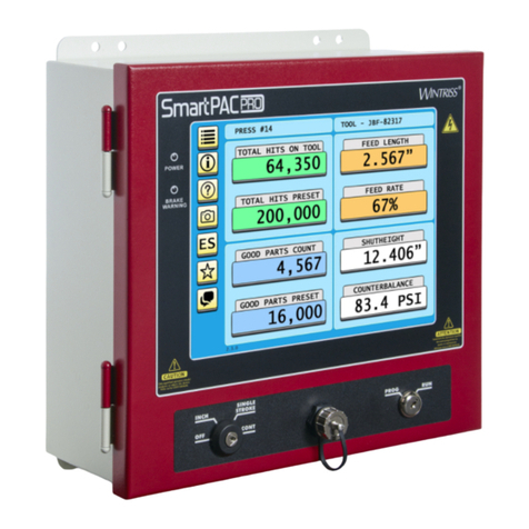
Wintriss SmartPAC PRO Servo User manual

Tech Support Hotline 800-586-8324 8-5 EST
www.wintriss.com
®
Servo
Wintriss Press Automation Control
1147100
Rev. A April 2020
®
Wintriss Controls Group, LLC
100 Discovery Way
Unit 110
Acton MA 01720 USA
Phone (800) 586-8324
Fax (978) 263-2048
PRINTED IN USA
®
Smartpacprologo


Thank you for purchasing a Wintriss product. We appreciate your business and want to do whatever
we can to ensure your satisfaction. Wintriss products are built to stay on the job day after day, and are
backed by an ironclad guarantee, international standards approvals, and unbeatable support.
Whenever you need assistance or service, we back all our products with excellent spare parts
inventories, training programs, and prompt repair service. We would like to share with you a list of
service options–probably the largest number of service options offered in the industry.
•Technical Assistance
We offer a toll-free line for technical assistance. Call our Wintriss Technical Support Hotline at
1-800-586-TECH (8324) should you have any questions about your equipment. Our technical
staff is ready to assist you Monday through Friday, 8 a.m. to 5 p.m. Eastern Time. In many cases
our experienced technical staff can resolve your inquiry right over the phone.
•Return Authorization
Please call our “800” number for a return authorization (RMA) number to return a product for
repair. Returned goods must arrive freight prepaid. In order to process your return quickly, we ask
that you provide us with the following pertinent information when you call: purchase order
number, shipping address, contact name and telephone number, and product type. The assigned
RMA number should appear on all packages returned to Wintriss Controls Group to ensure
prompt service.
At the time of requesting an RMA, you will be quoted a flat-rate repair price for the product you
are returning. We ask that you either fax us a PO for that amount or enclose the PO with the
returned item. This will enable us to ship the item back to you as soon as the repair has been
completed. If the item cannot be repaired or there are additional charges, you will be contacted
for approval.
Please be sure to carefully pack all returned items and ship to our Acton, MA location.
•Expedited Repair Program
Rush service providing 48 hour turnaround is available for most products upon request. An
Expedite Fee will be applied to our standard repair rate.
•Board Exchange Program
If your needs are urgent, you can take advantage of our Board Exchange (EX) program. Call our
“800” number between 8 a.m. and 5 p.m. EST and we will send a replacement to you overnight.
A fee does apply to this service. Contact Wintriss Technical Support at 800-586-8324 for details.
•Service Center
Our Service Center for product service is located at our headquarters in Acton, MA. If your
equipment requires repair, please contact us at 800-586-8324 to obtain a return authorization
number. Nationwide field service is also available. Contact the Wintriss Technical Support group
at 800-586-8324.
•Product Training
We also offer both product training and maintenance/troubleshooting courses at our Acton, MA
and Chicago-area facilities. On-site training is available from the factory or through your local
Wintriss representative.
•Restocking Charge
Returned goods are subject to a 20% restocking charge if returned for credit. The minimum
charge is $50, not to exceed $250 per item.
Whatever the product, we are committed to satisfying you with innovative engineering, quality
construction, reliable performance, and ongoing, helpful support. Call us whenever you need
assistance.


1147100 SmartPAC PRO Servo User Manual
Table of Contents 5
Table of Contents
Chapter 1 –Introduction...................................................................................................19
SmartPAC PRO Servo Standard Features .....................................................................................20
SmartPAC PRO Servo Options .....................................................................................................21
SmartPAC PRO Servo Operation..................................................................................................21
SmartPAC PRO Servo Settings.....................................................................................................21
Sensors Available for DiProPAC...................................................................................................22
Programmable Cam Channels........................................................................................................23
SmartPAC PRO Servo’s Three Modes of Operation.....................................................................23
SmartPAC PRO Servo Specifications ...........................................................................................24
Chapter 2 –Installation.....................................................................................................27
Before You Start............................................................................................................................28
Installation Guidelines...................................................................................................................28
Terminating Cable Shields.............................................................................................................31
Checking the Press.........................................................................................................................31
Mounting the SmartPAC PRO Servo Control Enclosure ..............................................................32
Installing SmartPAC PRO Servo as a Panel Mount ......................................................................33
Installing SmartPAC PRO Servo with Remote HMI.....................................................................34
Installing the MTS Linear Transducer...........................................................................................35
MountingtheTransducer....................................................................................................................................35
WiringtheTransducer.........................................................................................................................................37
WiringtheTransducertoDCPower.................................................................................................................39
Connecting Power Wiring –AC Powered Units ...........................................................................40
Connecting Power Wiring –24 VDC Powered Units....................................................................41
Connecting Stop Circuits and Input Check Circuit........................................................................41
MakingWiringConnections...............................................................................................................................42
SettingtheInput CheckVoltage Switch............................................................................................................42
Connecting to the Network............................................................................................................43
Adding or Upgrading DiProPAC or ProCamPAC.........................................................................43
Connecting DiPro Sensor Interface to SmartPAC PRO Servo......................................................45
Connecting Programmable Cam Channels....................................................................................49
Wiring Setup Mode Circuit............................................................................................................55
Wiring a Remote Reset Switch (Optional) ....................................................................................55
Wiring a Sensor-Disabled Output (Optional) ................................................................................55
Turning on Power to SmartPAC PRO Servo.................................................................................56
Verifying Installation of DiProPAC and ProCamPAC..................................................................57
Final Checkout...............................................................................................................................58
Set Up a “Test” Tool............................................................................................................................................58
Check StrokeLimits............................................................................................................................................59
ChecktheTop-stop Circuit.................................................................................................................................59
ChecktheEmergency-stopCircuit....................................................................................................................59
Check CamChannels..........................................................................................................................................59
TestComplete.......................................................................................................................................................59
What Next? ....................................................................................................................................60
Wiring Tables for SmartPAC PRO Servo Options........................................................................60

1147100 SmartPAC PRO Servo User Manual
6 Table of Contents
Chapter 3 –Displays and Operating Modes....................................................................63
SmartPAC PRO Operating Modes................................................................................................ 64
InitializationMode...............................................................................................................................................66
ProgramMode......................................................................................................................................................66
RunMode.............................................................................................................................................................66
On-Screen Data Entry ................................................................................................................... 66
On-ScreenNumericKeypad..............................................................................................................................66
On-ScreenKeyboard...........................................................................................................................................67
The “ALT” Menu .......................................................................................................................... 68
ScreenCaptures....................................................................................................................................................68
Chapter 4 –SmartPAC PRO Servo Initialization Mode...................................................71
POSITION SENSOR .................................................................................................................... 73
PositionSensorMode..........................................................................................................................................73
ResolverMotionMode(NormalMotion–LinkMotion)..............................................................................73
AngleWheelRotation(Clockwise–Counterclockwise)...............................................................................73
CounterSetupMode............................................................................................................................................74
CounterIncrementMode....................................................................................................................................74
INSTALLED OPTIONS............................................................................................................... 75
OPTIONS MANAGER................................................................................................................. 75
PREFERENCES............................................................................................................................ 76
SELECTLANGUAGE(OPTIONAL)............................................................................................................77
PRESS NAME .............................................................................................................................. 78
SELECT CAM NAMES (Optional).............................................................................................. 78
SET GLOBAL CAMS (Optional)................................................................................................. 80
CUSTOM SENSOR NAMES (Optional) ..................................................................................... 82
SENSOR ENABLE MODE (Optional)......................................................................................... 83
SelectingSensor EnableMode...........................................................................................................................83
EnablingSetupMode..........................................................................................................................................84
LINEAR SENSOR........................................................................................................................ 84
TOOL INFORMATION ............................................................................................................... 87
SECURITY ACCESS ................................................................................................................... 92
SettingSecurityAccess.......................................................................................................................................95
ChangingPasswords............................................................................................................................................96
BACKUP/RESTORE.........................................................................................................................................97
BackingUpToolstoaUSBDisk......................................................................................................................98
RestoringToolsfromaUSBDisk.....................................................................................................................98
SETUP DATA COMMS (Optional)............................................................................................. 98
SETUP NETWORK...................................................................................................................... 99
E-MAILFUNCTION.........................................................................................................................................99
SMARTVIEWFUNCTION...........................................................................................................................100
SETUPE-MAIL................................................................................................................................................100
CHANGENETWORKSETTINGS..............................................................................................................100
PRESSTYPE.....................................................................................................................................................100
DIAGNOSTICS .......................................................................................................................... 101
COMMUNICATIONS....................................................................................................................................102
SETCLOCK......................................................................................................................................................102
SAVETOUSBDISK......................................................................................................................................103
UPDATEFIRMWARE...................................................................................................................................104

SmartPAC PRO Servo User Manual 1147100
Table of Contents 7
Chapter 5 –Program Mode.............................................................................................105
Entering and Exiting Program Mode...........................................................................................106
TOOL MANAGER......................................................................................................................106
Creating aNewTool..........................................................................................................................................107
CopyinganExistingTool..................................................................................................................................108
CopyingToolTemplatetoaNewTool...........................................................................................................109
LoadingaTool....................................................................................................................................................110
ChangingSettingsforaLoadedTool..............................................................................................................111
Deleting aTool...................................................................................................................................................112
Tool Program Menu.....................................................................................................................112
TOOLNAME....................................................................................................................................................113
COUNTERS ................................................................................................................................114
SettingPresetValues..........................................................................................................................................115
ChangingCountValues....................................................................................................................................116
Clearing the Total Hits Counter...................................................................................................117
SettingBatch CounterOutputandIncrementModes....................................................................................117
SettingCounterIncrementAngle.....................................................................................................................118
SettingPartsper StrokeorStrokesperPart.....................................................................................................119
SettingBatch Pre-Load Counts........................................................................................................................120
DIE PROTECTION (Optional) ...................................................................................................120
UnderstandingSensorTerminology................................................................................................................121
Programming SensorSettings...........................................................................................................................125
Programming DiProPAC32Sensors..............................................................................................................136
CAM SWITCH............................................................................................................................142
SelectingaCamChannel..................................................................................................................................144
MakinganON/OFFSetting..............................................................................................................................145
SettingMultiple ON/OFFCycles.....................................................................................................................145
MakingaTimedOutputSetting.......................................................................................................................148
SettingDSVONChannelTiming...................................................................................................................149
Deleting Channel Settings.................................................................................................................................150
ViewingtheCamSummary.............................................................................................................................151
ViewingGlobalCams.......................................................................................................................................151
TOOL INFORMATION..............................................................................................................152
RAM POSITION.........................................................................................................................154
SENSOR ENABLE/DISABLE & STATUS (Optional)..............................................................156
ViewingSensorStatus.......................................................................................................................................157
EnablingorDisablingAllSensors...................................................................................................................157
TurningaSensorOfforOn..............................................................................................................................157
Chapter 6 –Run Mode ....................................................................................................159
Entering and Exiting Run Mode..................................................................................................160
Loading a Tool.............................................................................................................................161
Settings Locked, or Password Required ......................................................................................161
Displaying Multiple Faults ..........................................................................................................162
Opening the Ram Angle Window................................................................................................162
DISABLE (ENABLE) SENSORS...............................................................................................163
COUNTERS ................................................................................................................................165
DIE PROTECTION (Optional) ...................................................................................................167
AdjustingtheReadySignalforGreenSensors...............................................................................................168
AdjustingtheStrokePresetforGreenSpecial Sensors..................................................................................170
ViewingtheSensorSummary..........................................................................................................................170

1147100 SmartPAC PRO Servo User Manual
8 Table of Contents
ViewingSensorStatus.......................................................................................................................................171
AdjustingDiProPAC32Sensors.....................................................................................................................172
CAM SWITCH............................................................................................................................ 175
ViewingCamTiming........................................................................................................................................176
ViewingtheGlobalCamSummary................................................................................................................177
ViewingtheCamSummary.............................................................................................................................177
TOOL INFORMATION ............................................................................................................. 177
RAM POSITION......................................................................................................................... 179
ERROR/EVENT LOG ................................................................................................................ 180
LOAD NEW TOOL.................................................................................................................... 181
MESSAGING.............................................................................................................................. 182
SendingE-mailtoWintrissTechnicalSupport..............................................................................................184
Chapter 7 –Fault Messages...........................................................................................185
Responding to Fault Messages.................................................................................................... 186
Counter Preset Reached Messages.............................................................................................. 187
Messages for Equipment Problems............................................................................................. 187
Messages for Programming Problems......................................................................................... 188
Messages for Sensor Faults......................................................................................................... 189
Miscellaneous Fault Messages.................................................................................................... 191
Troubleshooting Using the Error/Event Log............................................................................... 192
Appendix A –Installing the Balluff Linear Transducer..............................................193
Mounting the Transducer ............................................................................................................ 193
WiringtheTransducer.......................................................................................................................................194
Glossary ..........................................................................................................................197
Index................................................................................................................................199
Setup Sheets
SmartPAC PRO Servo Setup Sheet
ProCamPAC Cam Switch –SmartPAC PRO Servo Setup Sheet Channels 1 –8
ProCamPAC Cam Switch –SmartPAC PRO Servo Setup Sheet Channels 9 –15
DiProPAC Die Protection –SmartPAC PRO Servo Setup Form Sensors 1-16
DiProPAC Die Protection –SmartPAC PRO Servo Setup Form Sensors 17-32

SmartPAC PRO Servo User Manual 1147100
Table of Contents 9
Wiring Diagrams at End of Manual
Figure 1. SmartPAC Pro Servo 8 Cams with DSI 2 MTS Internal PS
Figure 2. SmartPAC Pro Servo Press ProCamPAC 15 MTS Transducer Wiring Diagram
Figure 3. SmartPAC Pro Servo Press Wiring
Figure 4. DiProPAC Sensors 1-16 to DSI 2 Wiring Diagram
Figure 5. DiProPAC Sensors 17-32nto DSI 2 Wiring Diagram
Figure 6. SmartPAC Pro Servo Press ProCamPAC 8 Balluff Transducer Wiring Diagram
Figure 7. SmartPAC Pro Servo Press ProCamPAC 15 Balluff Transducer Wiring Diagram
Figure 8. SmartPAC Pro Loopback Test Wiring
List of Figures
Figure 1-1. SmartPAC PRO Servo Front Panel ...................................................................................19
Figure 2-1. Installation Overview.........................................................................................................30
Figure 2-2. SmartPAC PRO Servo Mounting Dimensions..................................................................32
Figure 2-3. SmartPAC PRO Servo Panel Mount Cutout Dimensions..................................................33
Figure 2-4. SmartPAC PRO Servo Panel Mount Dimensions .............................................................34
Figure 2-5. Real Time SmartPAC (RTS) Board Mounting Dimensions..............................................35
Figure 2-6. MTS Linear Transducer Dimensions.................................................................................36
Figure 2-7. SmartPAC PRO Servo Board –ProCamPAC Board, Left, Outlined in Red.....................37
Figure 2-8. ProCamPAC Linear Boards, Location of Components.....................................................38
Figure 2-9. MTS Linear Transducer Pinout .........................................................................................39
Figure 2-10. Wiring AC to Terminal Block, Inside Enclosure, Top Right ..........................................40
Figure 2-11. Location of Terminal Blocks TB1 to TB8.......................................................................41
Figure 2-12. Input Check Voltage Switch (S101) in the Factory Default (60-250V) Position............43
Figure 2-13. SmartPAC PRO Servo Board –DiProPAC Board, Right, Outlined in Red....................44
Figure 2-14. ProCamPAC Output Assembly .......................................................................................50
Figure 2-15. Cam Outputs Board .........................................................................................................51
Figure 2-16. TB302 and TB 303 for Wiring Relays to Equipment......................................................53
Figure 2-17. Install Suppressors Across AC Loads..............................................................................54
Figure 2-18. Installing a Diode Across a DC Load..............................................................................54
Figure 2-19. Main Program Menu........................................................................................................56
Figure 2-20. Main Program Menu........................................................................................................57
Figure 2-21. Main Initialization Menu.................................................................................................58
Figure 2-22. Installed Options Screen..................................................................................................58
Figure 3-1. SmartPAC PRO Servo.......................................................................................................63
Figure 3-2. SmartPAC PRO Servo Operating Modes, Showing Main Menus.....................................64
Figure 3-3. Numeric Keypad................................................................................................................67
Figure 3-4. SmartPAC PRO Servo On-screen Keyboard.....................................................................67
Figure 3-5. Save to USB Disk..............................................................................................................69
Figure 3-6. USB Disk Error Message...................................................................................................69
Figure 4-1. Main Initialization Menu...................................................................................................71
Figure 4-2. Main Initialization Menu, Next Items................................................................................72

1147100 SmartPAC PRO Servo User Manual
10 Table of Contents
Figure 4-3. Position Sensor Screen...................................................................................................... 73
Figure 4-4. Installed Options Screen.................................................................................................... 75
Figure 4-5. Options Manager Screen................................................................................................... 75
Figure 4-6. Main Initialization Menu................................................................................................... 76
Figure 4-7. Preferences Screen ............................................................................................................ 76
Figure 4-8. Select Language Screen .................................................................................................... 77
Figure 4-9.Press Name Entry Window................................................................................................ 78
Figure 4-10. Cam Channel Name Menu.............................................................................................. 79
Figure 4-11. Select Name for Cam Channel Screen............................................................................ 79
Figure 4-12. Global Cams Menu.......................................................................................................... 81
Figure 4-13. Global Cam Timing Type Screen.................................................................................... 81
Figure 4-14. Custom Sensor Names Screen......................................................................................... 82
Figure 4-15. Die Protection Enable Mode Selection Menu................................................................. 83
Figure 4-16. Linear Sensor Setup Screen............................................................................................. 85
Figure 4-17. Tool Information Setup Screen ....................................................................................... 88
Figure 4-18. Tool Information Name Screen....................................................................................... 89
Figure 4-19. Tool Information Units Selection Screen........................................................................ 90
Figure 4-20. Tool Information Setup Screen with Sample Entries...................................................... 92
Figure 4-21. Security Access Menu..................................................................................................... 92
Figure 4-22. Enter Password Window................................................................................................. 93
Figure 4-23. Set Passwords Menu........................................................................................................ 97
Figure 4-24. “Enter a New Password” Window .................................................................................. 97
Figure 4-25. Network Setup Utility Screen ......................................................................................... 99
Figure 4-26. Diagnostics Menu.......................................................................................................... 101
Figure 4-27. Communications Data Viewer Screen .......................................................................... 102
Figure 4-28. Set the Clock Screen ..................................................................................................... 103
Figure 5-1. Mail Program Menu........................................................................................................ 105
Figure 5-2. Tool Manager Screen...................................................................................................... 107
Figure 5-3. Enter New Tool Number Window.................................................................................. 107
Figure 5-4. Copy Tool Template Window......................................................................................... 108
Figure 5-5. Tool Template Copied..................................................................................................... 109
Figure 5-6. Load Tool Warning Window .......................................................................................... 110
Figure 5-7. Enter Password Window................................................................................................. 110
Figure 5-8. Enter Password Window................................................................................................. 111
Figure 5-9. Delete Tool Confirmation Message ................................................................................ 112
Figure 5-10. Tool Program Menu...................................................................................................... 113
Figure 5-11. Tool Name Entry Window............................................................................................ 114
Figure 5-12. Counters Screen ............................................................................................................ 114
Figure 5-13. Enter Password Window............................................................................................... 116
Figure 5-14. Change Count Confirmation Window........................................................................... 117
Figure 5-15. Counter Mode Selections Screen .................................................................................. 118
Figure 5-16. Advanced Counter Mode Selections Screen................................................................. 119
Figure 5-17. Die Protection Sensor Menu ......................................................................................... 121
Figure 5-18. Ready Signal Programming for a “Green” Sensor ........................................................ 123
Figure 5-19. Ready Signal Programming for a “Green Quick Check” Sensor .................................. 123
Figure 5-20. Ready Signal Programming for a “Green Constant” Sensor......................................... 124
Figure 5-21. “Enter General Password” Screen................................................................................. 126
Figure 5-22. Die Protection Sensor Menu with Auto Enable by Tool Counter................................. 126
Figure 5-23. Sensor Names Screen.................................................................................................... 127
Figure 5-24. Custom Sensor Names Screen....................................................................................... 128
Figure 5-25. Auto Enable by Sensor Counter Screen........................................................................ 128

SmartPAC PRO Servo User Manual 1147100
Table of Contents 11
Figure 5-26. Sensor Type Screen .......................................................................................................129
Figure 5-27. Sensor Stop Type Screen...............................................................................................130
Figure 5-28. Critical Angle Programming Screen..............................................................................131
Figure 5-29. Ready Signal Programming Screen...............................................................................133
Figure 5-30. Green Special Sensor Stroke Count Screen...................................................................134
Figure 5-31. Sensor Settings Screen...................................................................................................135
Figure 5-32. Sensor Summary Screen................................................................................................136
Figure 5-33. Tool Program Menu with DIPROPAC 1-16 and DIPROPAC 17-32 Items..................137
Figure 5-34. Die Protection Sensor 17-32 Menu................................................................................137
Figure 5-35. Sensor Names Screen with Stripper Function Highlighted ...........................................138
Figure 5-36. Sensor Type Screen with “GREEN” Highlighted .........................................................138
Figure 5-37. Sensor Stop Type Screen...............................................................................................139
Figure 5-38. Sensor Summary Screen Showing Ready Signals for Green Sensors...........................139
Figure 5-39. Sensor Settings Screen...................................................................................................140
Figure 5-40. Sensor Names Screen with Slug Detection Function Highlighted ................................140
Figure 5-41. Sensor Type Screen with “GREEN SPECIAL” Highlighted ........................................141
Figure 5-42. Sensor Summary Screen Showing Stroke Counts for Green Special Sensors...............141
Figure 5-43. Sensor Settings Screen...................................................................................................142
Figure 5-44. Cam Channel Menu.......................................................................................................143
Figure 5-45. “Enter General Password” Screen .................................................................................144
Figure 5-46. Cam Channel Program Type Menu...............................................................................144
Figure 5-47. Cam Channel On/Off Program Screen ..........................................................................145
Figure 5-48. Cam Channel On/Off Program Screen: One On/Off Arc..............................................146
Figure 5-49. Cam Channel On/Off Program Screen: Two On/Off Arcs............................................147
Figure 5-50. Cam Channel On/Off Program Screen: Three On/Off Arcs..........................................147
Figure 5-51. Cam Channel Timed Output Program Screen ...............................................................148
Figure 5-52. Cam Channel DSV ON Program Screen.......................................................................150
Figure 5-53. Cam Channel Deletion Confirmation Window .............................................................150
Figure 5-54. Cam Summary Screen ...................................................................................................151
Figure 5-55. Global Cam Summary Screen .......................................................................................152
Figure 5-56. Tool Information Screen................................................................................................153
Figure 5-57. “Enter General Password” Screen .................................................................................153
Figure 5-58. Ram Position Screen......................................................................................................154
Figure 5-59. “Enter General Password” Screen .................................................................................155
Figure 5-60. Sensor On/Off Status.....................................................................................................156
Figure 6-1. Main Run Menu...............................................................................................................160
Figure 6-2. No Tool Loaded Warning Window.................................................................................161
Figure 6-3. “Enter General Password” Screen ...................................................................................162
Figure 6-4. Display All Errors Message Window..............................................................................162
Figure 6-5. Ram Angle Window Displayed on Main Run Menu.......................................................163
Figure 6-6. Main Run Menu with SENSORS ENABLED.................................................................164
Figure 6-7. Disable Sensors Confirmation –Enter Password ............................................................164
Figure 6-8. Counters Screen...............................................................................................................166
Figure 6-9. Counters Screen with “Reload Batch Counters” Function ..............................................166
Figure 6-10. Die Protection Menu (Run Mode).................................................................................167
Figure 6-11. Ready Signal Programming Screen...............................................................................168
Figure 6-12. Sensor Status Screen......................................................................................................172
Figure 6-13. Main Run Menu with DiProPAC ..................................................................................172
Figure 6-14. Die Protection Sensor Menu for Sensors 17-32.............................................................173
Figure 6-15. Ready Signal Programming Screen, Run Mode............................................................174
Figure 6-16. Green Special Sensor Stroke Count Screen, Run Mode................................................174

1147100 SmartPAC PRO Servo User Manual
12 Table of Contents
Figure 6-17. Cam Switch Menu......................................................................................................... 175
Figure 6-18. Cam Timing Screen....................................................................................................... 177
Figure 6-19. Tool Number Information Screen ................................................................................. 178
Figure 6-20. Ram Position Screen ..................................................................................................... 179
Figure 6-21. Error Event Log............................................................................................................. 180
Figure 6-22. Tool Manager Screen.................................................................................................... 181
Figure 6-23. Load Tool Warning....................................................................................................... 182
Figure 6-24. Messaging Screen: List of Recipients........................................................................... 183
Figure 6-25. Messaging Screen: List of Messages............................................................................. 183
Figure 6-26. Select Attachment Screen.............................................................................................. 184
Figure 6-27. Sample E-mail to Wintriss Tech. Support..................................................................... 184
Figure 7-1. Error Code Window........................................................................................................ 186
Figure 7-2. Counter Preset Message Window ................................................................................... 186
List of Tables
Table 1-1. Specifications ..................................................................................................................... 24
Table 2-1. MTS Linear Transducer Wiring ......................................................................................... 39
Table 2-2. Stop and Input Check Circuit Wiring Connections: TB4................................................... 42
Table 2-3. DiPro Sensor Interface (DSI) 2 to SmartPAC PRO Servo Wiring, Sensors 1-8................ 46
Table 2-4. DiPro Sensor Interface (DSI) 2 to SmartPAC PRO Servo Wiring, Sensors 9-16.............. 47
Table 2-5. DiPro Sensor Interface (DSI) 2 to SmartPAC PRO Servo Wiring, Sensors 17-24............ 48
Table 2-6. DiPro Sensor Interface (DSI) 2 to SmartPAC PRO Servo Wiring, Sensors 25-32............ 48
Table 2-7. ProCamPAC Linear to Cam Output Assembly TB301 Wiring, Cams 1-8 ........................ 52
Table 2-8. ProCamPAC Linear to Cam Output Assembly TB301 Wiring, Cams 9-15 ...................... 53
Table 2-9. Connections to Relays........................................................................................................ 54
Table 2-10. Auxiliary Port (TB5) Wiring............................................................................................ 60
Table 2-11. SFI Port and Module Port (TB6) Wiring.......................................................................... 60
Table 2-12. Special Port and AUX (TB7) Wiring............................................................................... 61
Table 2-13. WPC Port and Spare 1 Port (TB8) Wiring ....................................................................... 61
Table 2-14. Stop and Input Check Circuit (TB4) Wiring .................................................................... 62
Table 3-1. Initialization, Program and Run Modes: Entry and Exit Procedures.................................. 65
Table 3-2. Button Descriptions............................................................................................................ 68
Table 4-1. Preferences ......................................................................................................................... 77
Table 4-2. Linear Sensor Setup Screen Field Definitions.................................................................... 86
Table 4-3. Tool Information Setup Screen: Abbreviations for Units................................................... 90
Table 4-4. Tool Information Setup Screen: Decimal Places and Formats........................................... 91
Table 4-5. Security Access Settings..................................................................................................... 94
Table 5-1. Instructions for Entering and Exiting Program Mode ...................................................... 106
Table 5-2. Additional On/Off Settings, 8-channel ProCamPAC: Examples ..................................... 146
Table 6-1. Instructions for Entering and Exiting Run Mode ............................................................. 161
Table 7-1. Communication Errors: SmartPAC PRO Servo Option Identified by Address Number . 191

HOW TO USE THIS MANUAL
This manual shows you how to install, set up, program, operate, and troubleshoot SmartPAC PRO
Servo, including the standard ProCamPAC and optional DiProPAC modules.
Chapter 1 provides an overview of the operation and features of SmartPAC PRO Servo.
Chapter 2 shows you how to install SmartPAC PRO Servo.
Chapter 3 shows you how to use the SmartPAC PRO displays.
Chapter 4 shows you how to use SmartPAC PRO Servo in Initialization mode, which is the mode you
select to make settings that apply to SmartPAC PRO Servo operation for all tools.
Chapter 5 shows you how to use SmartPAC PRO Servo in Program mode, which is the mode you
select to program settings that apply to SmartPAC PRO Servo operation for individual tools.
Chapters 6 shows you how to use SmartPAC PRO Servo in Run mode, which is the mode you select
to run the press and make minor adjustments to programmed settings.
Chapter 7 provides explanations of the messages that display on the SmartPAC PRO front panel
when a fault condition occurs or a counter preset is reached, and shows you how to correct SmartPAC
PRO Servo faults.
Appendix A shows you how to install a Balluff linear sensor.
The Glossary provides definitions of some of the terms used in the manual that may be unfamiliar to
you.
Setup sheets at the end of the manual provide forms on which you can maintain a record of
Initialization and Program settings for your SmartPAC PRO Servo.
Wiring diagrams (Figures 1 through 8) following the Setup sheets provide wiring connections for
SmartPAC PRO Servo, DiProPAC, ProCamPAC, and the SmartPAC PRO loopback test.


Important Highlighted Information
Important danger, warning, caution and notice information is highlighted throughout the manual as
follows:
DANGER
A DANGER symbol indicates an imminently hazardous situation, which, if not avoided, will result
in death or serious injury.
WARNING
A WARNING symbol indicates a potentially hazardous situation, which, if not avoided, could
result in death or serious injury.
CAUTION
A CAUTION indicates a potentially hazardous situation, which, if not avoided, may result in
property damage.
NOTICE
A NOTICE symbol indicates important information that you should remember, including tips to aid
you in performance of your job.


WARRANTY
Wintriss Controls warrants that Wintriss electronic controls are free from defects in material and
workmanship under normal use and service for a period of one year (two years for Shadow light
curtains) from date of shipment. All software products (SFC), electro-mechanical assemblies, and
sensors are warranted to be free from defects in material and workmanship under normal use and
service for a period of 90 days from date of shipment. Wintriss’s obligations under this warranty
are limited to repairing or replacing, at its discretion and at its factory or facility, any products
which shall, within the applicable period after shipment, be returned to Wintriss Controls freight
prepaid and which are, after examination, disclosed to the satisfaction of Wintriss to be defective.
This warranty shall not apply to any equipment which has been subjected to improper installation,
misuse, misapplication, negligence, accident, or unauthorized modification. The provisions of this
warranty do not extend the original warranty of any product which has either been repaired or
replaced by Wintriss Controls. No other warranty is expressed or implied. Wintriss accepts no
liability for damages, including any anticipated or lost profits, incidental damages, consequential
damages, costs, time charges, or other losses incurred in connection with the purchase, installation,
repair or operation of our products, or any part thereof.
Please note:
It is solely the user’s responsibility to properly install and maintain Wintriss controls and
equipment. Wintriss Controls manufactures its products to meet stringent specifications and cannot
assume responsibility for consequences arising from their misuse.
Wintriss Controls Group, LLC SmartPAC PRO Servo
100 Discovery Way USER MANUAL
Unit 110 1147100
Acton, MA 01720 Wintriss Controls Group, LLC
Telephone: (800) 586-TECH (8324) Copyright 2020
(978) 268-2700
Fax: (978) 263-2048
Internet: http://www.wintriss.com


1147100 SmartPAC PRO Servo User Manual
Chapter 1–Introduction 19
Chapter 1 –Introduction
SmartPAC PRO Servo is a smart modular interface for multiple press automation functions. With the
same user interface as SmartPAC PRO, which is widely used on standard mechanical presses,
SmartPAC PRO Servo tracks the position of the ram using a linear transducer instead of a resolver.
“Ram Position” settings for top and bottom linear position (see page 154) determine the stroke length
for each tool, which is converted to 0° to 180° for the downstroke and 181° to 359° for the upstroke.
Ram Position must be programmed properly for SmartPAC PRO Servo to work correctly.
CAUTION
Some Servo presses are capable of hitting the same part more than once at Bottom Dead Center
(BDC) before returning to the top of the stroke. You will have to note the angle ranges at which
repeated strokes occur. Any cams programmed within these ranges will actuate once for each hit.
Die protection ready signals programmed within these ranges will expect sensor actuation once for
each hit. If this is not feasible, please contact Wintriss Tech. Support to learn about new advanced
features.
Failure to comply with these instructions could result in property damage.
NOTICE
If this is a retrofit, do not disconnect existing linear and pressure sensors from your control.
Installation instructions. Identify the old inputs from which sensors are disconnected and the new
inputs to which they are connected.
Figure 1-1. SmartPAC PRO Servo Front Panel

1147100 SmartPAC PRO Servo User Manual
20 Chapter 1–Introduction
Every SmartPAC PRO Servo provides a magnetostrictive position transducer, eight-channel
programmable cam switch, and extensive counter capabilities. SmartPAC PRO Servo can make
instantaneous decisions for up to 8 cams (15 cams with the ProCamPAC 15 Linear board option) and
for up to 32 sensors if DiProPAC is installed. Because SmartPAC PRO Servo is microprocessor-
based, it can monitor or control all these different functions during a press stroke. Additionally, it
saves these settings for up to 2000 tools.
Programming and operation of SmartPAC PRO Servo are accomplished via its front panel, Figure
1-1. This includes a color liquid crystal (LCD) touch display and the Program/Run key switch.
Detailed instructions on how to use the display are provided in Chapter 3.
SmartPAC PRO Servo can be connected to a computer network, enabling press operation to be
monitored remotely and e-mail messages to be sent from the SmartPAC PRO Servo control.
SmartPAC PRO Servo can be configured with the following options:
•Up to 32-sensor die protection system
•Up to 16-channel programmable cam switch
•Up to 32-sensor in-die measurement system
•Solid-state dual-microprocessor-based clutch/brake control
•Two- or four-input load monitoring
•Automated shut-height and counterbalance control
•Automated press speed and lubrication control
•Servofeed interface
In addition, SmartPAC PRO Servo can be linked to Wintriss’s ShopFloorConnect Asset Utilization
Software (SFC) for data collection, analysis and reporting.
SmartPAC PRO Servo Standard Features
SmartPAC PRO Servo brings a multitude of press automation functions to one central location. The
following capabilities are standard features:
•All settings are made at the operator console, using SmartPAC PRO’s large, bright, color touch
screen.
•All tool programming is automatically saved in SmartPAC PRO’s non-volatile memory. To use
the same settings when you run the job again, simply re-load your stored tool number. SmartPAC
PRO Servo can save settings for 2000 tools.
•SmartPAC PRO Servo’s programmable cam switch provides cam timings for feeder signals and
other press equipment, including global cams for press operation functions and multiple on-off
cycles.
•Fault messages appear on the SmartPAC PRO display whenever the press malfunctions or
counter presets are reached. An error/event log maintains a record of the last 100 errors and
events.
•SmartPAC PRO Servo is Ethernet-ready, allowing the control to be connected to any computer
network. Network connectivity allows press operations to be viewed remotely via the SmartView
utility and e-mail messages, containing diagnostics and error log information, to be sent from the
SmartPAC PRO.
Table of contents
Other Wintriss Controllers manuals