Wirepath WP-TEST-FIBER-400 User manual

FIBER
© 2017 Wirepath™Technical Support: p. 866.838.5052 Ver. 170419-1000
WP-TEST-FIBER-400
Optical Power Meter
Owner’s Manual

HandheldOpticalPower Meter
1
Contents
Chapter 1. Standard Configuration….................................................... 2
Chapter 2. Overview................................................................................ 2
Chapter 3. Data Sheet............................................................................. 3
Chapter 4. Function… ............................................................................. 4
4.1
Front…..............................................................................................................4
4.2
Sides… ............................................................................................................. 8
4.3
Top… ...............................................................................................................................9
4.4
Back................................................................................................................10
Chapter 5. Software. ............................................................................. 11
Chapter 6. Operation Instruction & Notes… ......................................11
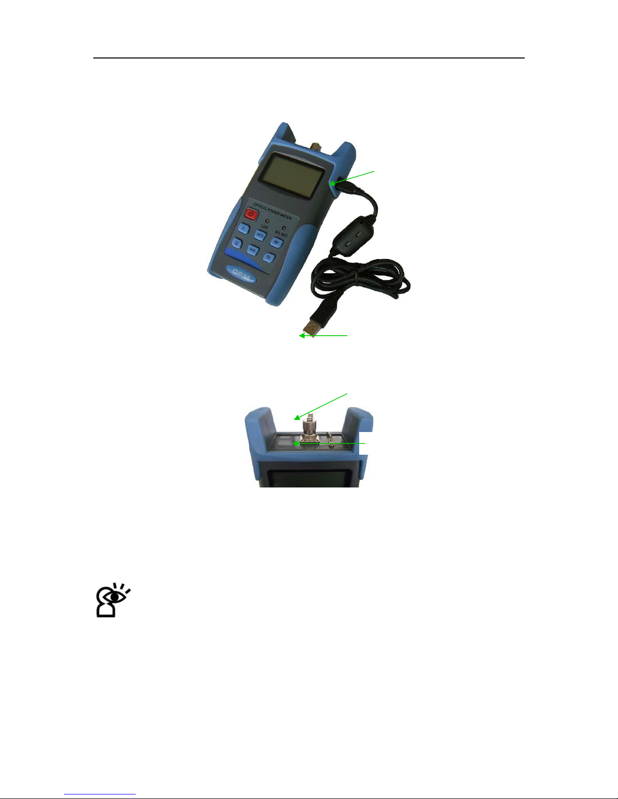
6.1
PoweringtheOpticalPowerMeter… ................................................................11
6.2
Poweron the optical PowerMeter… .................................................................13
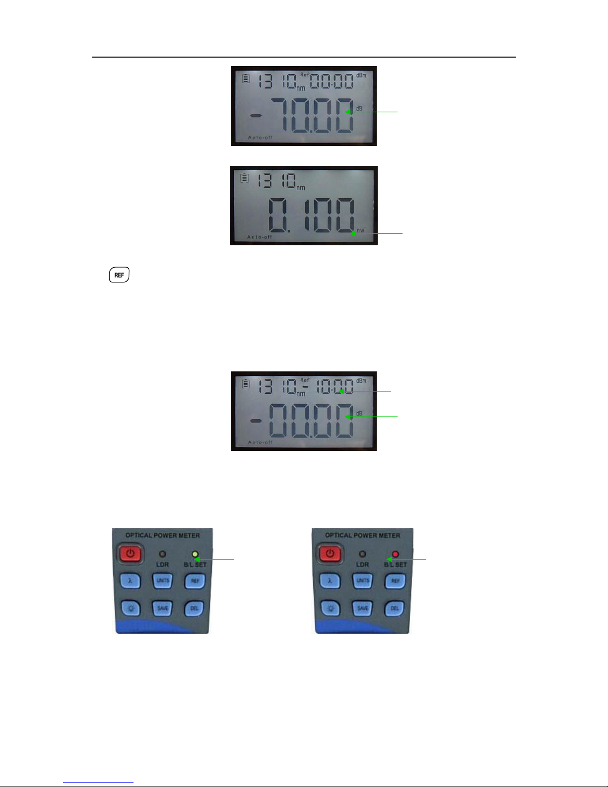
6.3
Backlightsetting...............................................................................................13
6.4
OutputPowermeasurement............................................................................ 14
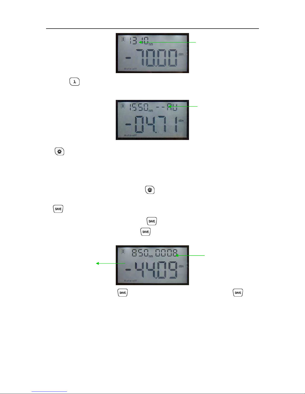
6.5
WavelengthAutomaticIdentification.................................................................17
6.6
Frequencydetection.........................................................................................18
6.7
Power off…...........................................................................................................18
Chapter 7. Troubleshooting .................................................................18
Chapter 8 General Maintenance .......................................................... 19
Chapter 9 Warranty............................................................................... 19

HandheldOpticalPower Meter
2
Chapter 1: Standard Configuration
No.
name
qty
1
Optical Power Meter
1
2
User Manual
1
3
USB cable
1
4
CD
1
5
1.5V AA battery (not included)
3
6
Power Supply Unit
1
7
Cotton Swabs
1
Chapter 2: Overview
The WP-TEST-FIBER-400 Optical Power Meter is a newly designed fiber optic tester intended
for the installation, engineering acceptance, and maintenance of fibernetworks.
Compared with other power meters, the WP-TEST-FIBER-400 Power Meter has more functions,
including automatic wavelength identification, auto wavelength switching, intelligent backlight, and
data saving via USB port.
Combined with its matched handheld optical light source, it offers a quick and accurate testing
solution on both single mode and multimode fibers.
WaveID:Autowavelengthidentification&switching
FrequencyID:Autofrequencyidentification
2 types of backlight modes: manual or automatic (ambient light-driven), indicated by red or
green LED lights.
Intelligentbacklight
Storage of up to 1000 records, downloadable via USB cable
USBcommunicationportfordownloadingsavedtestingrecords
Adjustable/storablereferencepowerlevel
User self-calibratingfunction
Auto-offfunction
Upto200hrs battery life

HandheldOpticalPower Meter
3
Chapter 3: Data Sheet
Model
A
C
Calibration Wavelength(nm)
850/1300/1310/1490/1550/1625
Detector type
InGaAs
Measurement Range(dBm)
-70 - +6
-50 -+26
Uncertainty (dB)
±0.15(3.5%)
linearity (dB)
±0.02
Display resolution(dB)
0.01
Frequency ID(Hz)
270, 330,1K, 2K
Wave ID(nm)
850,1300, 1310, 1490, 1550, 1625
Date Storage Capacity
1000
Communication Port
USB
Standard Connector
FC /2.5mm universal
Optional Optical Connector
SC/FC Type
Optional Optical Connector
None
Alkaline battery
3*AA, 1.5V
Power Adapter(V)
8.4
Battery Operating time (h)
200 without backlight
Operation Temperature(C)
-10 - +60
Storage Temperature(C)
-25 - +70
Dimension(mm)
175*90*44.5
Weight(g)
231
Note: Battery operating time is effected by backlight power operation. If power backlight is running continuously,
operation time will be shorter

HandheldOpticalPower Meter
4
Chapter 4: Function
4.1 Front
(1)
(2)
(3)
4-1
(1)
Power Key: Press to turn unit on or off
Power Saving Mode: Quickly press Power Key to activate the Auto-Shut Off. When active, the
unit will automatically shut off after 10 minutes idle time, whether using battery power supply or
AC power supply. In Auto-Shut off mode, “auto-off” will display on the bottom left of the screen.
This power saving setting is the default setting. The power meter will be in this mode when first
turned on. Quickly press the power key to turn off auto power saving mode.
Power Saving (Auto-off)
(2)
WavelengthSelection/WavelengthIdentification
Quickly press this key to select the wavelength. It will display on the top left of the LCD screen.
1310nm is the default wavelength.
(10)
(9)
(8)
(7)
(6)
(5)
(4)

HandheldOpticalPower Meter
5
Calibrated wavelength
Press for 2 seconds to enter wavelength auto-identification mode. The upper
right ofthescreen willdisplay“AU”. Press and hold this key to quit this function.
Wavelength auto-identification
(3)
B
acklight control (two modes of back light control; press this key to select):
•
“LDR” indicates the intelligent backlight control mode. Power meter will
activate/deactivate the backlight in 15 seconds based on ambient light. This is the
defaultmode.
•
Back light control key mode. Press
to turn on/off the back light
(4) Saving/Data-Viewkey 。
Data-saving: can save up to 1000 records. . The screen will display the data saving
number. Ifsavingthedata,doublepress toconfirm
Current saving data
(wavelength, output
power-dBm)
Data Saving No.
Data view: Press and hold to enter the data view interface. Quickly press to view
the data. Pressing again steps back through saved records.

HandheldOpticalPower Meter
6
(5)
Delete/CancelKey。
0008
……
0001
1.
Deleting Data: When viewing the data, press to delete therecord.
2.
Cancel saving: When in the saving mode, press to cancel the current data saving.
(6)
Unit SelectionKey
Press this key to switch between absolute measurement (dBm) and relative measurement
(dB) and xW of the optical power.
mW, dBmconversion:10 log(mW)=(dBm)
mW ,uW,nW conversion:1mW=103uW=106nW
dBm

HandheldOpticalPower Meter
7
dB
xW
(7)
REFsetting
Stores the current power value as the reference value (displayed on the top right of the LCD
screen) while “Ref” also displays on the top right. It will compare the current power with the
reference power and show the relative power value in dB.
The relationship between relative value (dB), absolute value (dBm), and Ref value: relative value=
︱absolute value︱-︱Ref︱
Ref value setting
Relative
value
setting
(8)
“B/L SET” backlight indicator
Lights indicate backlight control modes. Green light indicates that “LDR” intelligent backlight
control mode is active. Red light indicates that key-control mode is active.
Indicator
(Green)
Indicator
(red)
(9)
“LDR” Intelligentbacklightcontrol
In the intelligent backlight control mode, the controller will automatically adjust the backlight
according to ambient light in order to save the power.

HandheldOpticalPower Meter
8
(10)
Screen
Displays the data and the instrument’s working mode.
4.2 Sides
(1)
Power Supply unitport 4-2left side 4-3 right side
Connect with the AC adaptor (fig. 4-4)。
AC adaptor
Power Supply
Unit
4-4
Note:Use only the power supply unit supplied with the tester. Using other kinds of PSU may
damage the instrument.
(1)
(2)
Power Plug

HandheldOpticalPower Meter
9
(2)
(2)
USBPort。
Use the USB cable supplied to connect the Optical Power Meter to the USB port on PC (fig. 4-5).
。
Mini USB Port
Universal USB(connect with PC)
4-5
4.3 Top
(1)
4-6
(1)
Dust Cap
Dust Cap: Place the dust cap over the connectors when not in use to protect the optical connector
(2)
OpticalConnector。
The standard for this power meter connector is SC & Φ2.5mm.
Note: When changing the optical connector, be careful of the connector and the
end-face. FC connector can connect with FC adaptor; Φ2.5mm universal connector can
connect with FC, SC, or ST adaptor. (Fig 4-9)
For LC testing, utilize included SC to LC reference patch cords and use included LC-type
adaptors for double-ended testing.

HandheldOpticalPower Meter
10
FC Patch Cord SC Patch Cord ST Patch Cord
4-9
Note: dust ontheconnectorwill affecttheaccuracyof themeasurement value. Clean the
connectorandthepatchcordendbeforetesting. Useisopropylalcoholandacottonswabtoclean
the connector. Moisten the cotton swab with alcohol, insert the cotton swab in the connector,
slightly rotating the cotton swab. Dry using a second dry cotton swab. Fig. 4-10
。
Cotton Swab
4-10
4.4 Back
(1)
(2)
(3)
4-11
(1) Label
Content includes function and instrument information

HandheldOpticalPower Meter
11
(2)
Bracket
Collapsible metal bracket can be adjusted 0~90.
(3)
BatteryPack
Holds 3 1.5 AA batteries.
Note: when inserting the batteries, note their positive (+) and negative (-) connector
orientation. The negative battery connector should be against the spring. Recycle used batteries.
Chapter 5 Software
The data capture software for this product can downloaded from the product page support tab at
snapav.com. Instructions for setup and use are included in the download.
Chapter 6 Operation Instruction and Notes
6.1 Powering the Optical Power Meter
The optical power meter can be powered by battery or AC power, giving total flexibility for most testing
sites and situations
6.1.1 AA battery
When usingAAbattery, will display on the left top of the screen (6-1)。
Battery Power indicator
PowerGrade:
6-1
70% - 100%power
40% - 70%power
30% - 40%power
20% - 30% power。
less than 20% power. The power meter will power off.

HandheldOpticalPower Meter
12
Inserting the battery, 6-2
6-2
Push the clip fastener on the battery compartment cover down. Remove the battery compartment
cover and remove all three batteries, making a note of their positive and negative connector
orientation. The negative battery connector should be against the spring. Insert 3 new 1.5VV AA
batteries. Refit the battery compartment cover. The clip fastener should click shut.
Note :Insert the batteries with their positive and negative connectors correctly aligned.
6.1.2 Power Supply Unit
When the battery is empty, the power supply unit can be used. At the top left of the screen,
( 6-3) will be displayed. When the battery is in the power meter and still charged, the tester
will default to the AC power supply.
AC power
supply
indicator
6-3
When using the AC adaptor, connect the power plug (pictured) and insert it in the AC adapter port.

HandheldOpticalPower Meter
13
AC adaptor
Power Supply
Unit
Power Plug
6-4
Note: Only usethepower supply unit suppliedwiththetester. Using another type of power
supply may damage the instrument.
6.2 Powering on the optical power meter
Insert the battery or the PSU and press on the tester. At this time the laser is still off. The
display will show no data as shown infigure 6-5
Electricity indicator Calibratedwavelength
Power saving
mode(Auto-off)
6-5
dBm value
When the tester is in standby, press key to cancel or enable auto-off function.If auto-off
function is selected, the “Auto-off” will display ontheleftbottomof thescreen.
6.3 Backlight setting
After starting the optical power meter, press and hold tochoose backlight control mode.
6.3.1
“LDR” Intelligentbacklightcontrolmode
Press and hold when “B/L SET” is green (6-6). After 10 seconds, the green indicator will turn

HandheldOpticalPower Meter
14
off. In LDR the controller will automatically adjust the backlight to theoutsidelightwithin 15 seconds to
save power.
Indicator (Green)
6.3.2
KeyControlBacklightMode.
6-6
Press and hold , “B/L SET” (indicator turns red as in fig. 6-7) to enter key control backlight mode.
After 10 seconds the indicator t u r n s off. Quick press to turn the backlightON/OFF.
Indicator (red)
6.4 Output power measurement 6-7
Please also refer to the included FOA instructional on testing and visit www.foa.org.
6.4.1
Removedustcap,connect thepatch cordthat will be used as a0dB reference.
Note: Make sure the connector and the end of patch cord are clean. Make sure to
connect the correct patch cord.
6.4.2
Selectthewavelength
Quick press to select the calibrated wavelength. NOTE: if the selected wavelength is not the
same as the optical light source source wavelength measurement errors will occur. There are 6
calibration wavelengths available for selection. Always ensure that the power meter and light source
are set to the same wavelength prior to testing (6-8).

HandheldOpticalPower Meter
15
Calibration wavelength
6.4.3
Unitswitch
6-8
Press to switch between absolute measurement (dBm), relative measurement (dB), and xW of
the optical power(6-9).
dBm
dB
xW
6.4.4Relativevaluemeasurement
6-9
Each wavelength can set the Ref value. Press to set the current value as the 0 dBref value
and automatically calculate out therelative value (top right ofthe screen will display the “ref” and setting
dBm value 6-10) prior to linktesting.
Relative value setting
6-10

HandheldOpticalPower Meter
16
6.4.5 Data processing
Data saving and deleting. The power meter can store up to 1000 data records. To record a power
measurement, press . The right top of the screen will display the data saving record number,
e.g.: “0008”(6-11). To confirm the data record saved, double press to confirm or to
cancel the record. It is recommended to keep a written record by saved number to be added to the
“Notes” field data after it is downloaded.
Data saving No.
Current saving
data (wavelength,
dBm)
6-11
Data view & delete. Press and hold , to view the saving record number. The screen will
display the most recently saved data. Quickly press to view the data from the last record (6-
12). Press to delete the record. Press and hold to exit the dataview.
0008
……
0001
6-12

HandheldOpticalPower Meter
17
6.5 Wavelength Automatic Identification
Connect power meter with its matched light source.
Enable light source. Under “Wave ID” operation mode, press . Select desire wavelength.
Hold
for few seconds. Light source will be enter Wave ID mode. “--AU” will be
shown on the upper right of LCD as an indication.
Once the ID information is detected from light source (press to change wavelength), after 3
to 5 seconds, the information on the optical power meter will change automatically according to
the light source. Refer to figure 6-28.
Toexit Wave ID mode hold down to exit Wave ID mode from the power mete. Hold down
to exit Wave ID mode from the light source.
Matched Light Source Power
Meter
6-28
850nm (xxdBm)
1300nm (xxdBm)
1310nm (xxdBm)
1550nm (xxdBm)
1310nm (xxdBm)
1550nm (xxdBm)
850nm (xxdBm)
1300nm (xxdBm)

HandheldOpticalPower Meter
18
6.6 Frequency Detection
Light source and power meter will both operate units at 270Hz in almost all testing conditions.
Note:Frequency ID and wave ID cannot be operated at the same time.
To avoid risk of serious eye damage, do not look into the optical port of laser source at any time.
6.7 Power off
Automatic power off: When auto-off function is activated, the unit will turn itself off automatically after
10minutes idle, whether on battery or AC power
Manual power off: Under any operation mode, hold down for a few seconds to turn the unit off.
Note: The unit will store the last calibration wavelength andbacklight control mode automatically.
This will be the default setting when the unit is next turned on.
Chapter 7 Troubleshooting
Problems
Possible cause
Solution
Faint display on the LCD
screen
1.
Power is off
2.
The battery poweris
too low
1.
Press
key.
2.
Change thebatteries
Inaccurate measurements
1.
Optical connector is not
clean.
2.
Incorrectfiber
connection
1.
Clean opticalconnectors
2.
Reconnect thefiber

HandheldOpticalPower Meter
19
Chapter 8: General Maintenance
8.1
Always keep the connector ports of your powermeter clean.
8.2
Do not use badquality fiber optic connectors/adaptors to avoiddamagingthedetectorinterface
andgreatlyaffectingtheperformanceof theunit.
8.3
Useonlytheadaptor supplied.
8.4
Placedust-proof cap over the optical ports when unit is not in use.
8.5
Connect/disconnect fiber connectors/adapters carefully toavoidscratches on the portof the
powermeter.
8.6
Clean the optical port of power meter regularly. Clean using cotton swabs supplied and
isopropyl alcohol as directed.
Chapter 9 Quality Warranty
Details of warranty terms and conditions are given as below:
1)
The company warrants that the light source will be free from defects in material and
workmanship for a period of
18 months.
The date will be started from the date of goods
shipment.
2)
If any faults occur due to quality problems of the product during the warranty period, the
company promises to repair or replace free of charge. The freight cost and related taxes
will be shared by both parties. The company will pay the shipping cost from customer side
to our factory and pay the import taxes related. Customer will pay the shipping cost from
ourfactory to customer side and its local import taxes accordingly.
3)
This warranty
is limited to
defects in workmanship and materials and does not cover
damages from accident, acts of god, neglect, wrong usage or abnormal conditions of
operation.
4)
The company will charge corresponding fees for the cost of materials, repair and shipping
in conditions ofbelow:
Defects occurred under normal use and service but out of the warranty period.
Failures and damage occurred not because of defects in material and
workmanship of products.
Failures and damage occurred because of failing to comply with the Operation
Instructions.
Abnormal conditions of operation or handling such as artificial damage, or operating in
abnormal conditions such as high temperatures, high voltage, humidity and etc. We will
charge according tothe actual failure rating.
Table of contents