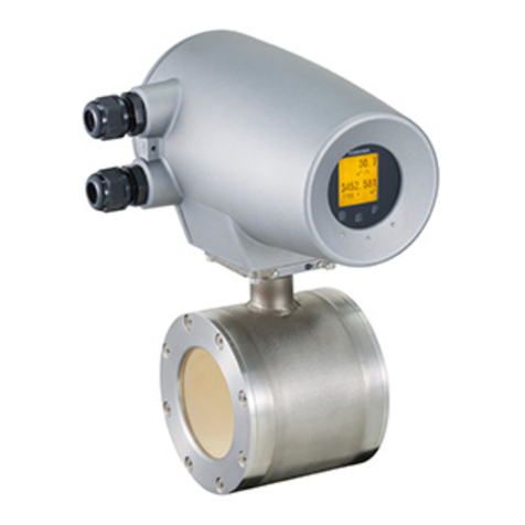
TIC-LF470H
・When combined with the LF232 converter:
Approximately 14W (25VA)
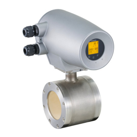
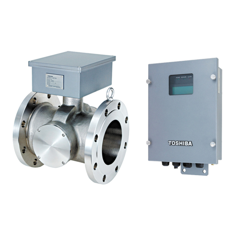
Model LF470 Detectors
Fluid pressure:
-
15 to 150 psi, or
-
1.0 to 10 bar
(-0.1 to 1 MPa)
Principal materials:
Measurement tube – Alumina ceramics
Electrodes – Platinum
Pipe connection port:
Standard – 316 stainless steel
Option –Ti (titanium),
Polyvinyl chloride (shock-resistant)+
Ta (Tantalum) for grounding plate,
Polyvinyl chloride (shock-resistant)+
Pt-Ir grounding plate,
Hastelloy C (Equivalent)
Dedicated preformed cables:
・Signal cable – 2-wire shielded chloroprene
sheathed cable
Overalllength:0.28inch(7mm)
Length: 0.20 inch (5m)
・Excitation cable –3-wiren chloroprene sheathed
cable
Overall length: 0.28 inch (7mm)
Length:
0.20 inch (5m)
Coating: phthalic acid resin coating pearl-gray
colored
Weight: approximately 2.2 lb (1.0 kg)
(for each size excluding cables)
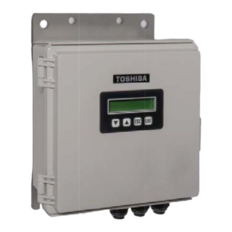
Model LF622 converters
Input signals
Analog signal —the voltage signal from detector,
proportional to process flow rate (for LF622
separate type converter).
Digital input DI
Signal type: 20 to 30Vdc voltage signal
Input resistance: 2.7k
Number of inputs: one point
Note: DI cannot be used with the Modbus
communication.
DI function — One of the following functions can be
assigned to the DI signal.
Range switching — Selects either the higher or lower
range in the unidirectional or bidirectional 2-range
setting.
Totalizer control — ‘Starts and stops’ or ‘Rest and
start’ the built-in totalizer.
Fixed-value outputs —Outputs fixed-values for
current and pulse outputs for loop check.
Zero adjustment — Executes zero adjustment
(on-stream at zero flow rate).
Output signals
Current output:
4–20mAdc (load resistance 0 to 750)
Note: The current output cannot be used with the
PROFIBUS-PAcommunication.
(Refer table 6 for details)
Digital outputs — Two points are available as
follows.
Digital output DO1 :
Output type: Transistor open collector
Number of outputs: One point
Output capacity: 30Vdc, 200mA maximum
Note: DO1 cannot be used if Modbus communication
connection is 3 lines.(Refer table 6 for details)
Digital output DO2 :
Output type:
Solid-state relay output (non polarity)
Number of outputs: One point
Output capacity: 150Vdc, 150mA maximum
or 150Vac (peak to peak), 100mA maximum
Note: DO2 cannot be used with the Modbus
communication.(Refer table 6 for details)
DO1 and DO2 functions — One of the following
functions can be assigned to DO1 and/or DO2.
• Pulse output (available only for DO1, DO2)
Pulse rate: Max 10kHz (10,000pps) (DO1)
Max 100Hz ( 100pps) (DO2)
(Over 1kpps, auto-setting)
Pulse width: 0.3 to 500ms (but less than half of the
period for 100% flow rate)
Note: The same and simultaneous pulse is not
available between DO1 and DO2.)
• Multi-range selection outputs (Note 1)
• High, High high, Low, and/or Low low alarm
outputs (Note 2)
• Empty pipe alarm output
• Digital Output Active Status (DO1 and DO2)
(Note 2)
• Preset count output
• Converter failure alarm output
Note 1: Two outputs (DO1 and DO2) are needed for
4-range switching and forward/reverse 2-range
switching.
Note 2:Normal Open (default set) or Normal Close is
selected for alarm outputs when programming.
When power failure occurs, unit will be fault to
Normal Open.
