IMPORTANT SAFETY INSTRUCTIONS
WARNING: To reduce the risk of re or electric shock, do not expose this apparatus in or near rain
or moisture.
1. Read and keep these instructions for future reference.
2. Do not use this apparatus near water.
3. Clean only with a dry cloth.
4. Do not block any ventilation openings. Install according to manufacturer’s instructions.
5. Do not install near any heat sources such as radiators, heat registers, stoves or other apparatus
(Including ampliers) that produce heat.
6. Do not override the safety purpose of the polarized or grounding-type plug. A polarized plug has
two blades - one wider than the other. A grounding type plug has two blades and a third
grounding prong. The wide blade or the third prong is provided for your safety. If the provided
plug does not t into your outlet, consult an electrician for replacement of the obsolete outlet.
7. Protect the power cord from being walked on or pinched particularly at plug, convenience
receptacles, and the point where it exits from the apparatus.
8. Only use attachments/accessories specied by the manufacturer.
9. To completely disconnect this equipment from the AC mains, disconnect the power supply cord
plug from the AC receptacle.
10. This is CLASS II apparatus with double insulation, and no protective earth provided.
The lightning ash with arrowhead
symbol, within an equilateral triangle, is
intended to alert the user to the presence
of un-insulated dangerous voltage within
the product’s enclosure that may be of
sufcient magnitude to constitute a risk of
electric shock to persons.
The exclamation point within an
equilateral triangle is intended to alert the
user to the presence of important
operating and maintenance (servicing)
instructions in the literature
accompanying the appliance.
CAUTION
CAUTION: TO REDUCE THE RISK OF
ELECTRICAL SHOCK.
DO NOT REMOVE COVER. NO USER
SERVICEABLE PARTS INSIDE.
REFER SERVICING TO QUALIFIED
SERVICE PERSONNEL.
CAUTION
CAUTION: TO REDUCE THE RISK OF
ELECTRICAL SHOCK.
DO NOT REMOVE COVER. NO USER
SERVICEABLE PARTS INSIDE.
REFER SERVICING TO QUALIFIED
SERVICE PERSONNEL.
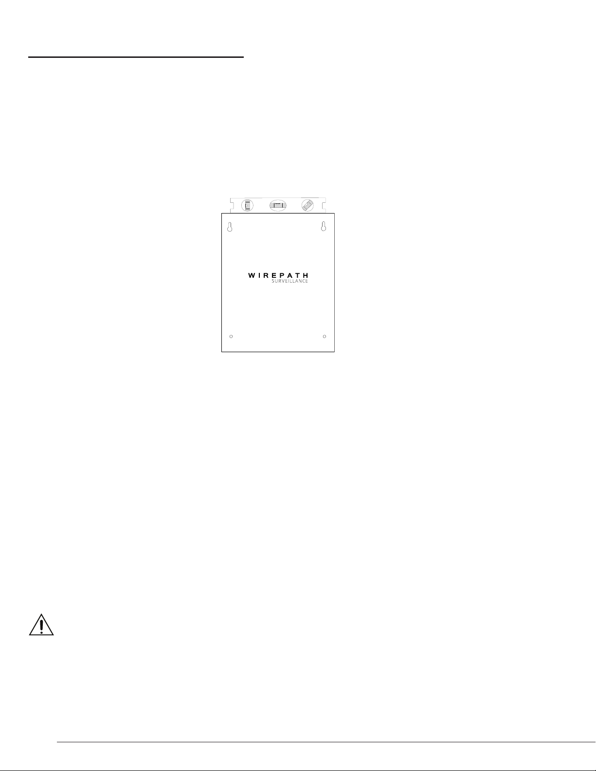
Important Note: Do Not connect AC power to the WPS-PS until all connections
to the outputs are made. Disconnect power when making any connections to
the WPS-PS.