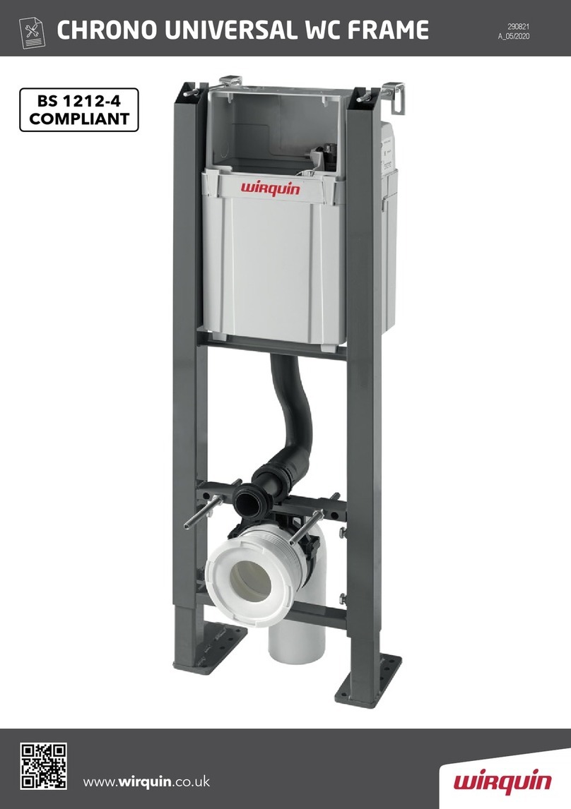
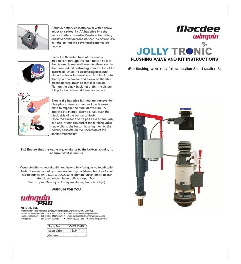
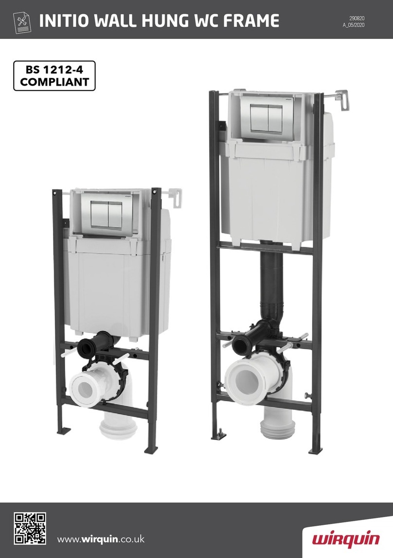
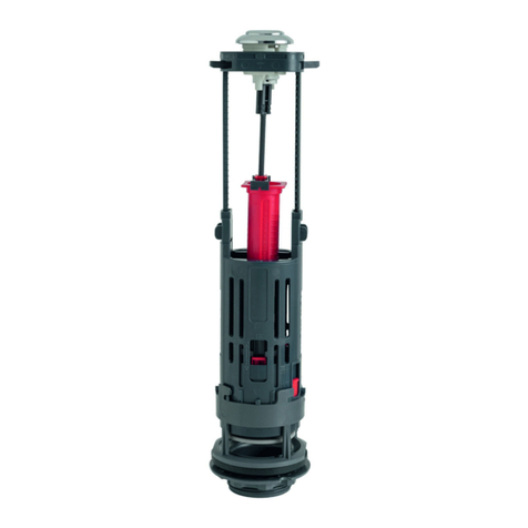
Wirquin PRO CHRONO User manual

1h30 1h00 30 mn 15 mn 10 mn
1 2 3
clic !
CHRONO
Instruction de montage
Assembly instructions
NOT 216241_A - 03/2014
12
Attachment of the flush plate
Fixation de la plaque de commande
9
12
3
1h30 1h00 30 mn 15 mn 10 mn
1 2 3
clic !
1h30 1h00 30 mn 15 mn 10 mn
1 2 3
clic !
1h30 1h00 30 mn 15 mn 10 mn
1 2 3
clic !
1
2
1 - Clipper le cable du mécanisme au support de commande Ken
tirant horizontalement (figure 1),
2 - Clipper le support de commande Kdans le support de plaque J
(figure 2),
3 - Installer la plaque de commande Len l’inclinant contre le
cadre en poussant vers le haut (action 1de la figure 3) puis
rebasculer la plaque sur la partie haute du cadre (action 2de
la figure 3).
1 - Clip the mechanism cable to the control support Kby
pulling horizontally (figure 1),
2 - Clip the control support Kin the plate support J
(figure 2),
3 - Install the flush plate Lby tilting it against the frame while
pushing upwards (action 1of figure 3) and tilt it back onto
the top part of the frame (action 2on figure 3).

2 11
1h30 1h00 30 mn 15 mn 10 mn
1 2 3
clic !
A
B
C
F
G
H
L
I
J
K
MR
S
W
TUV
NO
PQ
D
E
B
A
C
Nomenclature des pièces
Parts list Attachment of the flush plate
Fixation de la plaque de commande
8
1
23
1h30 1h00 30 mn 15 mn 10 mn
1 2 3
clic !
1h30 1h00 30 mn 15 mn 10 mn
1 2 3
clic !
1h30 1h00 30 mn 15 mn 10 mn
1 2 3
clic !
1 - Retirer le tunnel gabarit A, en tirant horizontalement,
2 - Ouvrir le robinet d’eau (figure 1),
3 - Insérer le support de plaque Jdans l’emplacement de la plaque de
commande et fixer le à l’aide des crochets support I(figure 2et 3) en
respectant le sens de montage (sens des triangles en rouge sur la figure 2),
le support doit se verrouiller sur l’épaisseur de l’habillage.
1 - Remove the tunnel template A, by pulling horizontally,
2 - Open the water valve (figure 1),
3 - Insert the plate support Jin the flush plate position and secure it with
support hooks I(figure 2and 3) in the correct mounting direction
(orientation of the red triangles on figure 2), the support must be
locked onto the thickness of the casing.
1h30 1h00 30 mn 15 mn 10 mn
1 2 3
clic !
1h30 1h00 30 mn 15 mn 10 mn
1 2 3
clic !
1h30 1h00 30 mn 15 mn 10 mn
1 2 3
clic !

10 3
Attachment of the pan
Fixation de la cuvette
7
1 - Retirer les protections BC,
2 - Positionner le joint de cuvette Hsur la manchette Get insérer
partiellement la manchette dans le tube de descente (figure 1),
3 - Insérer le manchon d’évacuation extensible Fsur sortie de la
cuvette * (figure 2),
4 - Enfoncer l’enbout du manchon Fdans la pipe, puis mettre en
place la cuvette sur les tiges de filletée S(figure 3) en guidant la
manchette dans l’entrée de la cuvette (figure 4),
5 - Fixer la cuvette avec les visseries TUVet W(figure 5).
1
4
2
3 5
1
1
2
2
2
*: longueur de la manchette 51mm à 110 mm / length of the sleeve 51 mm to 110 mm
1 - Remove the protective devices BC,
2 - Position the pan seal Honto the sleeve Gand partially insert the
sleeve in the flushpipe (figure 1),
3 - Insert the extendable waste sleeve Fon the pan outlet * (figure 2),
4 - Push the sleeve fitting Fin the pipe, and position the pan on the
threaded rods S(figure 3) guiding the sleeve into the pan inlet
(figure 4),
5 - Fix the pan with the threaded fasteners TUVand W(figure 5).
N° QT Designation/ Description
A1Robinet flotteur / Float valve
B1Mecanisme double chasse à cable / Dual-flush cable-operated mechanism
C1Pipe coudée / Elbow pipe
D1Bride / Flange
E6Goujons / Studs
F1Manchon d’évacuation Flexible sans découpe / Waste sleeve Hose without cut-out
G1Manchette coulissante sans découpe / Sliding sleeve without cut-out
H1Joint de cuvette / Pan seal
I2Crochet support de plaque de commande / Flush plate support hook
J1Support de plaque de commande / Flush plate support
K1Support commande à cable / Cable-operated flush support
L1Plaque de commande (livrée séparément) / Flush plate (delivered separately)
M2Patte de fixation murale / Wall mounting bracket
N2Cheville plastique / Plastic plug
O2Tire-fond / Lag screw
P2Rondelle Ø8 / Washer Ø8
Q2Ecrou M8 / Nut M8
R2Tige filetée murale M8 L200mm / Wall threaded rod M8 L200mm
S2Tige filetée support de cuvette M12 L200mm empreinte hexagonale /
Pan support hexagonal head threaded rod M12 L200mm
T2Rondelle Ø12 / Washer Ø12
U4Ecrou M12 / Nut M12
V2Centreur cuvette / Pan centring piece
W2Cache écrou / Nut cover
A1Tunnel gabarit de plaque de commande / Flush plate template tunnel
B1Obturateur pipe et tube / Pipe and tube plug
C2Protection tiges filetées / Protection for threaded rods

4 9
1
1
1
1h30 1h00 30 mn 15 mn 10 mn
1 2 3
clic !
Réglage de pose du bâti support
Adjustment of the support frame installation
1 - Positionner le bâti en fonction de la canalisation, positionner
la pipe Cdans le collier si besoin,
2 - Réaliser le réglage en hauteur en fonction de la ligne de
1 mètre (voir Zoom) ou en fonction de la hauteur finale
souhaitée,
3 - Une fois le réglage terminé, bloquer les vis hexagonales 1.
1 - Position the frame in line with the pipework, position the
pipe Cin the collar if required,
2 - Adjust the height according to the 1-metre line (see Zoom) or
according to the desired height,
3 - Once the adjustment is completed, lock the hexagonal head
screws 1.
1000 mm
220 mm
6
1h30 1h00 30 mn 15 mn 10 mn
1 2 3
clic !
Casing
Habillage
1 - Avant la réalisation de l’habillage, positionner les protections BC,
2 - Clipper le tunel Gabarit Aau couvercle du réservoir (figure 1),
3 - Réaliser l’habillage (figure 2).
1 - Before assembling the casing, position the protective devices BC,
2 - Clip the tunnel template Ato the cistern cover (figure 1),
3 - Assemble the casing (figure 2).
171 mm
131 mm
581,5 mm
220 mm
320 mm
355 mm
Ø139 mm
180 mm*
Ø60mm
M12
1
2
1
1
2
2
*: ou 230 mm suivant le modèle de cuvette / or 230 mm depending on the model of the pan

8 5
Adjustment of the pan position
Réglage de positionnement de la cuvette
5
l1 l2
1
1
1h30 1h00 30 mn 15 mn 10 mn
1 2 3
clic !
L = l1 + l2 +20mm
1h30 1h00 30 mn 15 mn 10 mn
1 2 3
clic !
1h30 1h00 30 mn 15 mn 10 mn
1 2 3
clic !
1 - Visser un écrou Usur chacune des tiges filetées S,
2 - Les visser ensuite sur le bâti comme sur le schéma 1,
3 - Régler la longueur de dépassement en additionnant l’épaisseur
de l’habillage (cloison + finition) l1 + la profondeur du trou de
fixation de la cuvette l2 et ajouter 20mm,
4 - Serrer les écrous.
1 - Screw a nut Uon to each threaded rod S,
2 - Then screw them on to the frame as indicated on the diagram 1,
3 - Adjust their extruding length by adding the casing thickness
(wall + finish) l1 + the depth of the pan securing hole l2 and
add 20mm,
4 - Tighten the nuts.
Raccordement à l’évacuation
Connection to drainage system
2
1h30 1h00 30 mn 15 mn 10 mn
1 2 3
clic !
1h30 1h00 30 mn 15 mn 10 mn
1 2 3
clic !
1h30 1h00 30 mn 15 mn 10 mn
1 2 3
clic !
1 - Découper et ébavurer la pipe Csi nécessaire,
2 - Déposer de la colle PVC sur le pourtour en contact avec
la sortie d’évacuation,
3 - Clipser le collier Dà la pipe.
1 - Cut and deburr the pipe Cif required,
2 - Apply PVC adhesive around the edge in contact with the
drain outlet,
3 - Clip the collar Dto the pipe.

6 7
3
1h30 1h00 30 mn 15 mn 10 mn
1 2 3
clic !
1h30 1h00 30 mn 15 mn 10 mn
1 2 3
clic !
M
E
NOPQR
60 mm
Fixation du bâti support
Securing the support frame
1 - Réaliser le perçage pour les fixations des pieds (figure 1),
2 - Insérer les gougeons à frapper Eet les serrer avec une clé,
3 - Positionner les équerres murales et les fixer au mur.
Découper la tige si besoin.
1 - Drill the hole for the feet mountings,
2 - Insert the drive studs Eand tighten them with a wrench,
3 - Position the wall brackets and fix them to the wall. Cut the
rod if required.
1
2
Water connection
Raccordement en eau
4
1h30 1h00 30 mn 15 mn 10 mn
1 2 3
clic !
1h30 1h00 30 mn 15 mn 10 mn
1 2 3
clic !
1
1 - Raccorder le bâti à l’alimentation d’eau,
2 - Astuce : vous pouvez positionner votre robinet
d’alimentation en position arrière (Astuce 1).
1 - Connect the frame to the water supply,
2 - Tip: you can position the supply valve in the rear position
(Tip 1).
14 Nm max
1h30 1h00 30 mn 15 mn 10 mn
1 2 3
clic !

8 5
Adjustment of the pan position
Réglage de positionnement de la cuvette
5
l1 l2
1
1
1h30 1h00 30 mn 15 mn 10 mn
1 2 3
clic !
L = l1 + l2 +20mm
1h30 1h00 30 mn 15 mn 10 mn
1 2 3
clic !
1h30 1h00 30 mn 15 mn 10 mn
1 2 3
clic !
1 - Visser un écrou Usur chacune des tiges filetées S,
2 - Les visser ensuite sur le bâti comme sur le schéma 1,
3 - Régler la longueur de dépassement en additionnant l’épaisseur
de l’habillage (cloison + finition) l1 + la profondeur du trou de
fixation de la cuvette l2 et ajouter 20mm,
4 - Serrer les écrous.
1 - Screw a nut Uon to each threaded rod S,
2 - Then screw them on to the frame as indicated on the diagram 1,
3 - Adjust their extruding length by adding the casing thickness
(wall + finish) l1 + the depth of the pan securing hole l2 and
add 20mm,
4 - Tighten the nuts.
Raccordement à l’évacuation
Connection to drainage system
2
1h30 1h00 30 mn 15 mn 10 mn
1 2 3
clic !
1h30 1h00 30 mn 15 mn 10 mn
1 2 3
clic !
1h30 1h00 30 mn 15 mn 10 mn
1 2 3
clic !
1 - Découper et ébavurer la pipe Csi nécessaire,
2 - Déposer de la colle PVC sur le pourtour en contact avec
la sortie d’évacuation,
3 - Clipser le collier Dà la pipe.
1 - Cut and deburr the pipe Cif required,
2 - Apply PVC adhesive around the edge in contact with the
drain outlet,
3 - Clip the collar Dto the pipe.

4 9
1
1
1
1h30 1h00 30 mn 15 mn 10 mn
1 2 3
clic !
Réglage de pose du bâti support
Adjustment of the support frame installation
1 - Positionner le bâti en fonction de la canalisation, positionner
la pipe Cdans le collier si besoin,
2 - Réaliser le réglage en hauteur en fonction de la ligne de
1 mètre (voir Zoom) ou en fonction de la hauteur finale
souhaitée,
3 - Une fois le réglage terminé, bloquer les vis hexagonales 1.
1 - Position the frame in line with the pipework, position the
pipe Cin the collar if required,
2 - Adjust the height according to the 1-metre line (see Zoom) or
according to the desired height,
3 - Once the adjustment is completed, lock the hexagonal head
screws 1.
1000 mm
220 mm
6
1h30 1h00 30 mn 15 mn 10 mn
1 2 3
clic !
Casing
Habillage
1 - Avant la réalisation de l’habillage, positionner les protections BC,
2 - Clipper le tunel Gabarit Aau couvercle du réservoir (figure 1),
3 - Réaliser l’habillage (figure 2).
1 - Before assembling the casing, position the protective devices BC,
2 - Clip the tunnel template Ato the cistern cover (figure 1),
3 - Assemble the casing (figure 2).
171 mm
131 mm
581,5 mm
220 mm
320 mm
355 mm
Ø139 mm
180 mm*
Ø60mm
M12
1
2
1
1
2
2
*: ou 230 mm suivant le modèle de cuvette / or 230 mm depending on the model of the pan

10 3
Attachment of the pan
Fixation de la cuvette
7
1 - Retirer les protections BC,
2 - Positionner le joint de cuvette Hsur la manchette Get insérer
partiellement la manchette dans le tube de descente (figure 1),
3 - Insérer le manchon d’évacuation extensible Fsur sortie de la
cuvette * (figure 2),
4 - Enfoncer l’enbout du manchon Fdans la pipe, puis mettre en
place la cuvette sur les tiges de filletée S(figure 3) en guidant la
manchette dans l’entrée de la cuvette (figure 4),
5 - Fixer la cuvette avec les visseries TUVet W(figure 5).
1
4
2
3 5
1
1
2
2
2
*: longueur de la manchette 51mm à 110 mm / length of the sleeve 51 mm to 110 mm
1 - Remove the protective devices BC,
2 - Position the pan seal Honto the sleeve Gand partially insert the
sleeve in the flushpipe (figure 1),
3 - Insert the extendable waste sleeve Fon the pan outlet * (figure 2),
4 - Push the sleeve fitting Fin the pipe, and position the pan on the
threaded rods S(figure 3) guiding the sleeve into the pan inlet
(figure 4),
5 - Fix the pan with the threaded fasteners TUVand W(figure 5).
N° QT Designation/ Description
A1Robinet flotteur / Float valve
B1Mecanisme double chasse à cable / Dual-flush cable-operated mechanism
C1Pipe coudée / Elbow pipe
D1Bride / Flange
E6Goujons / Studs
F1Manchon d’évacuation Flexible sans découpe / Waste sleeve Hose without cut-out
G1Manchette coulissante sans découpe / Sliding sleeve without cut-out
H1Joint de cuvette / Pan seal
I2Crochet support de plaque de commande / Flush plate support hook
J1Support de plaque de commande / Flush plate support
K1Support commande à cable / Cable-operated flush support
L1Plaque de commande (livrée séparément) / Flush plate (delivered separately)
M2Patte de fixation murale / Wall mounting bracket
N2Cheville plastique / Plastic plug
O2Tire-fond / Lag screw
P2Rondelle Ø8 / Washer Ø8
Q2Ecrou M8 / Nut M8
R2Tige filetée murale M8 L200mm / Wall threaded rod M8 L200mm
S2Tige filetée support de cuvette M12 L200mm empreinte hexagonale /
Pan support hexagonal head threaded rod M12 L200mm
T2Rondelle Ø12 / Washer Ø12
U4Ecrou M12 / Nut M12
V2Centreur cuvette / Pan centring piece
W2Cache écrou / Nut cover
A1Tunnel gabarit de plaque de commande / Flush plate template tunnel
B1Obturateur pipe et tube / Pipe and tube plug
C2Protection tiges filetées / Protection for threaded rods

2 11
1h30 1h00 30 mn 15 mn 10 mn
1 2 3
clic !
A
B
C
F
G
H
L
I
J
K
MR
S
W
TUV
NO
PQ
D
E
B
A
C
Nomenclature des pièces
Parts list Attachment of the flush plate
Fixation de la plaque de commande
8
1
23
1h30 1h00 30 mn 15 mn 10 mn
1 2 3
clic !
1h30 1h00 30 mn 15 mn 10 mn
1 2 3
clic !
1h30 1h00 30 mn 15 mn 10 mn
1 2 3
clic !
1 - Retirer le tunnel gabarit A, en tirant horizontalement,
2 - Ouvrir le robinet d’eau (figure 1),
3 - Insérer le support de plaque Jdans l’emplacement de la plaque de
commande et fixer le à l’aide des crochets support I(figure 2et 3) en
respectant le sens de montage (sens des triangles en rouge sur la figure 2),
le support doit se verrouiller sur l’épaisseur de l’habillage.
1 - Remove the tunnel template A, by pulling horizontally,
2 - Open the water valve (figure 1),
3 - Insert the plate support Jin the flush plate position and secure it with
support hooks I(figure 2and 3) in the correct mounting direction
(orientation of the red triangles on figure 2), the support must be
locked onto the thickness of the casing.
1h30 1h00 30 mn 15 mn 10 mn
1 2 3
clic !
1h30 1h00 30 mn 15 mn 10 mn
1 2 3
clic !
1h30 1h00 30 mn 15 mn 10 mn
1 2 3
clic !

1h30 1h00 30 mn 15 mn 10 mn
1 2 3
clic !
CHRONO
Instruction de montage
Assembly instructions
NOT 216241_A - 03/2014
12
Attachment of the flush plate
Fixation de la plaque de commande
9
12
3
1h30 1h00 30 mn 15 mn 10 mn
1 2 3
clic !
1h30 1h00 30 mn 15 mn 10 mn
1 2 3
clic !
1h30 1h00 30 mn 15 mn 10 mn
1 2 3
clic !
1
2
1 - Clipper le cable du mécanisme au support de commande Ken
tirant horizontalement (figure 1),
2 - Clipper le support de commande Kdans le support de plaque J
(figure 2),
3 - Installer la plaque de commande Len l’inclinant contre le
cadre en poussant vers le haut (action 1de la figure 3) puis
rebasculer la plaque sur la partie haute du cadre (action 2de
la figure 3).
1 - Clip the mechanism cable to the control support Kby
pulling horizontally (figure 1),
2 - Clip the control support Kin the plate support J
(figure 2),
3 - Install the flush plate Lby tilting it against the frame while
pushing upwards (action 1of figure 3) and tilt it back onto
the top part of the frame (action 2on figure 3).
Table of contents
Other Wirquin Plumbing Product manuals
Popular Plumbing Product manuals by other brands

Hans Grohe
Hans Grohe Axor Citterio 39133000 quick start guide

Gessi
Gessi SOGNI 57963 Bath Mixing Program

Kohler
Kohler K-5664 Installation and care guide

Kohler
Kohler Flipside 17492T installation instructions

Symmons
Symmons Duro SLC3612PP Operation & maintenance manual

Kohler
Kohler K-470 Installation and care guide

Spectrum Brands
Spectrum Brands Pfister Tisbury LG42-TB0 Quick installation guide

Kallista
Kallista P23013-CR installation instructions

Columbia Products
Columbia Products SANI-LAV 727F operating manual

Helvex
Helvex U16105 installation guide

Axor
Axor Edge 46140007 Instructions for use/assembly instructions

Bradley
Bradley S19-220HFP Installation