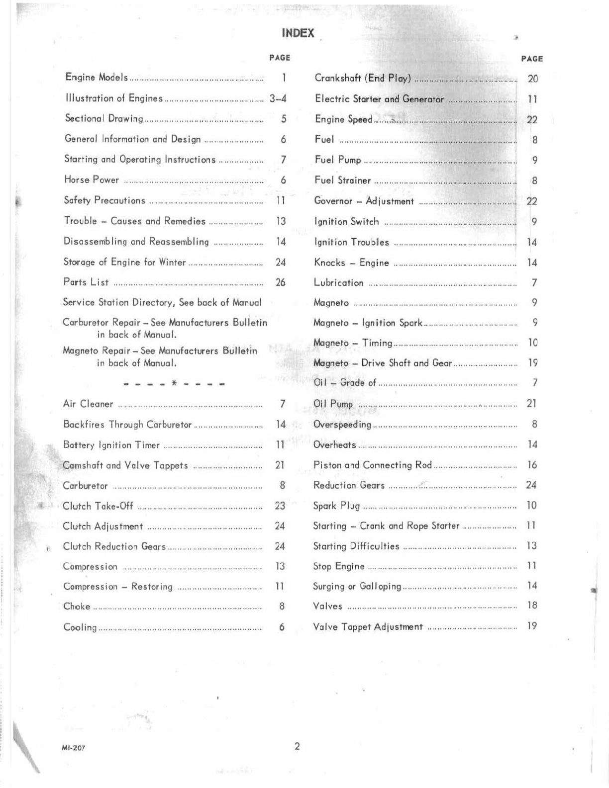
INDEX
PAGE
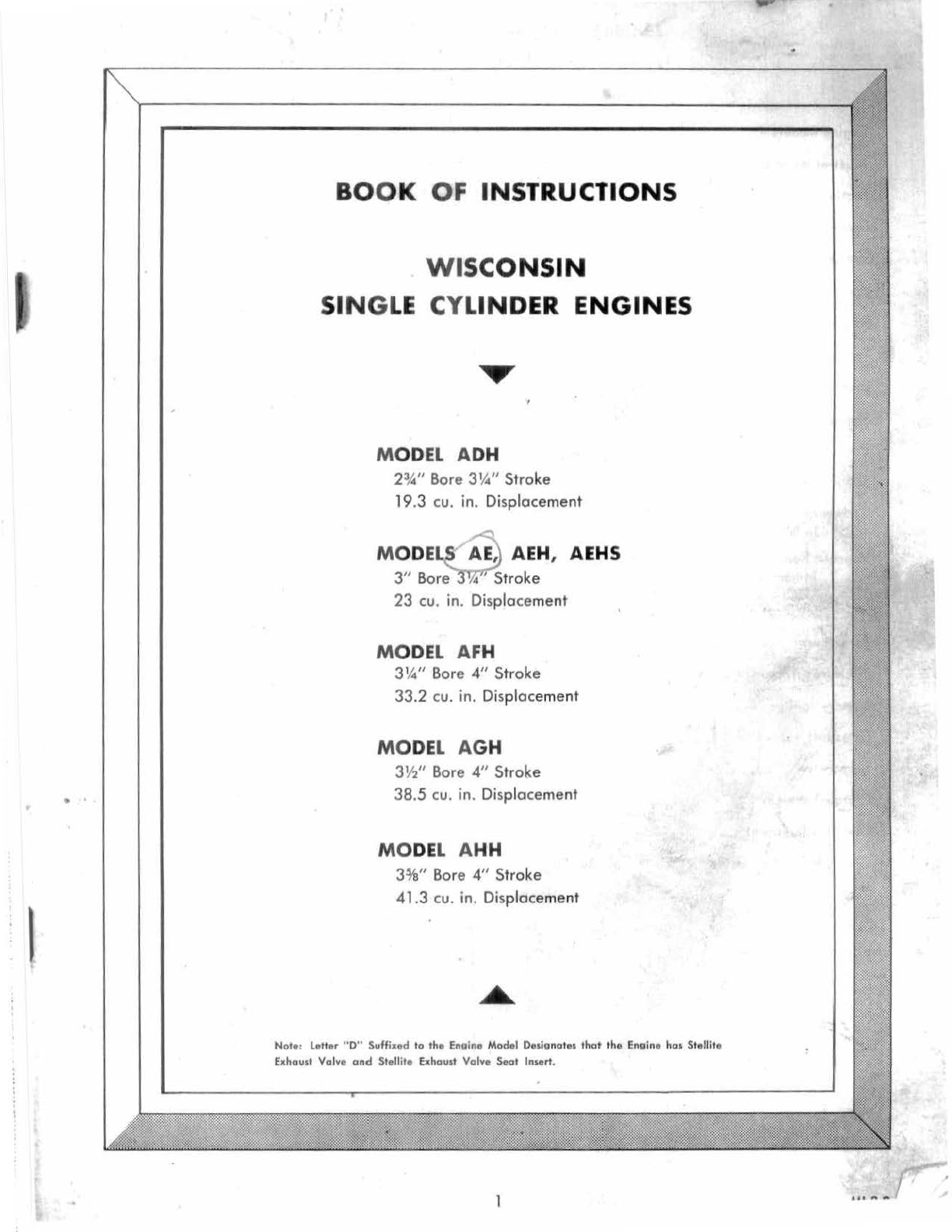
En
gine
Models...................
..
...................
..
....
..
......
Illustration
of
Engines
..
..
.
..
.
..
..............................
3-4
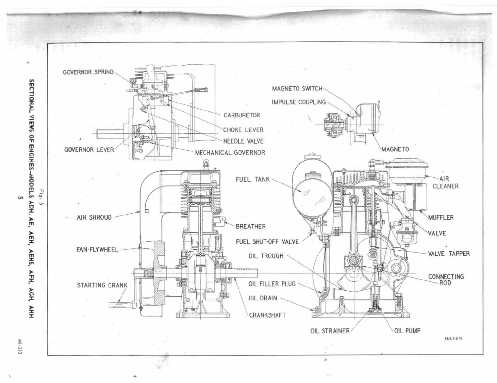
Sectional
Drawing ..............................................
..
General
Information
and
Design
......................
..
Start
ing
and
Operating
Instructions
................
..
Horse
Power
..............
..
......,...............................
..
5
6
7
6
Safety
Precautions
............................................
..
11
Trouble-
Causes
and
Remedies
......................
13
Disassembling
and
Rea
ss
embling
..
................
..
14
Storage
of
Engine
for Winter ...... .... ....................
24
Parts
List
........
..
......................
.. ..
..........
....
........
..
26
Service
Station
Di
rect
ory,
See
bock
of
Manual
Carburetor
Repair-
See
Manufacturers
Bulle
tin
in
back
of
Manual.
Magneto
Repa
i
r-
See
Manufacturers
Bulletin
in
bock
of
Manual.
- - - - *
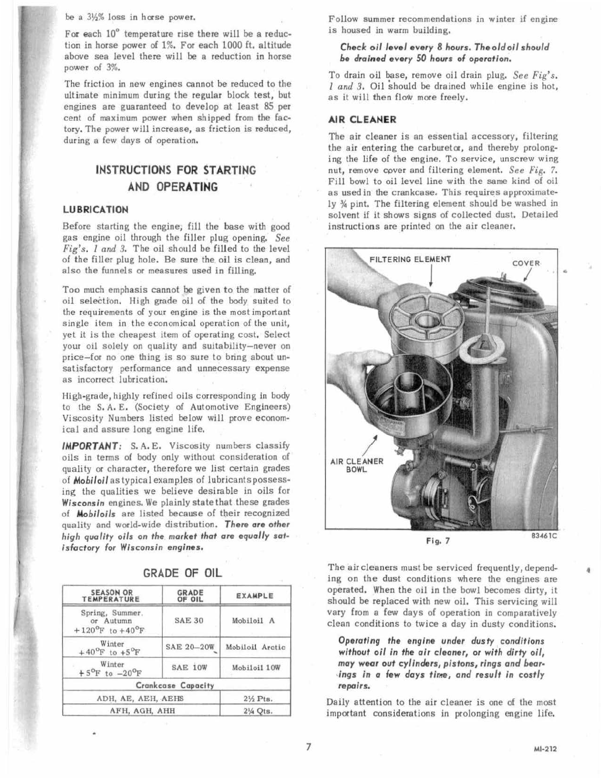
Air
Cleaner
7
Backfire
s
Through
Carburetor.
...........................
14
Battery
Igni
tion
Timer
......................................
..
11
Ca
mshaft
and
Valv
e
Tappets
..
.... ........ ..............
21
Carburetor
.........................................................
..
8
Clutc
h
Tok
e-Off ....
..
....
..
.... .... .... .... ......
..
..............
23
Clutch
Adjustment
..............
..
..........
..
.... ..............
24
Clutch
Reduction
Gears
......
..
..............................
24
Compression
........................................................
13
Compression
-
Rest
oring .............. ...... ......
..
....
..
11
Choke
.................................................................... 8
Cooling
....
.... ..
..............
..
................ ................
..
....
..
6
Ml-207 2
PAGE
Crankshaft
(
End
Ploy)..........................................
20
Electric
Starter
and
Generator
..
..
....
....
..
..
............
11
Engine
Speed
.......
:-..
............
..
..................
..
..............
22
Fuel
............................
..
..
....
..
....
..
............................ 8
Fuel
Pump
..
..........
..
................................................ 9
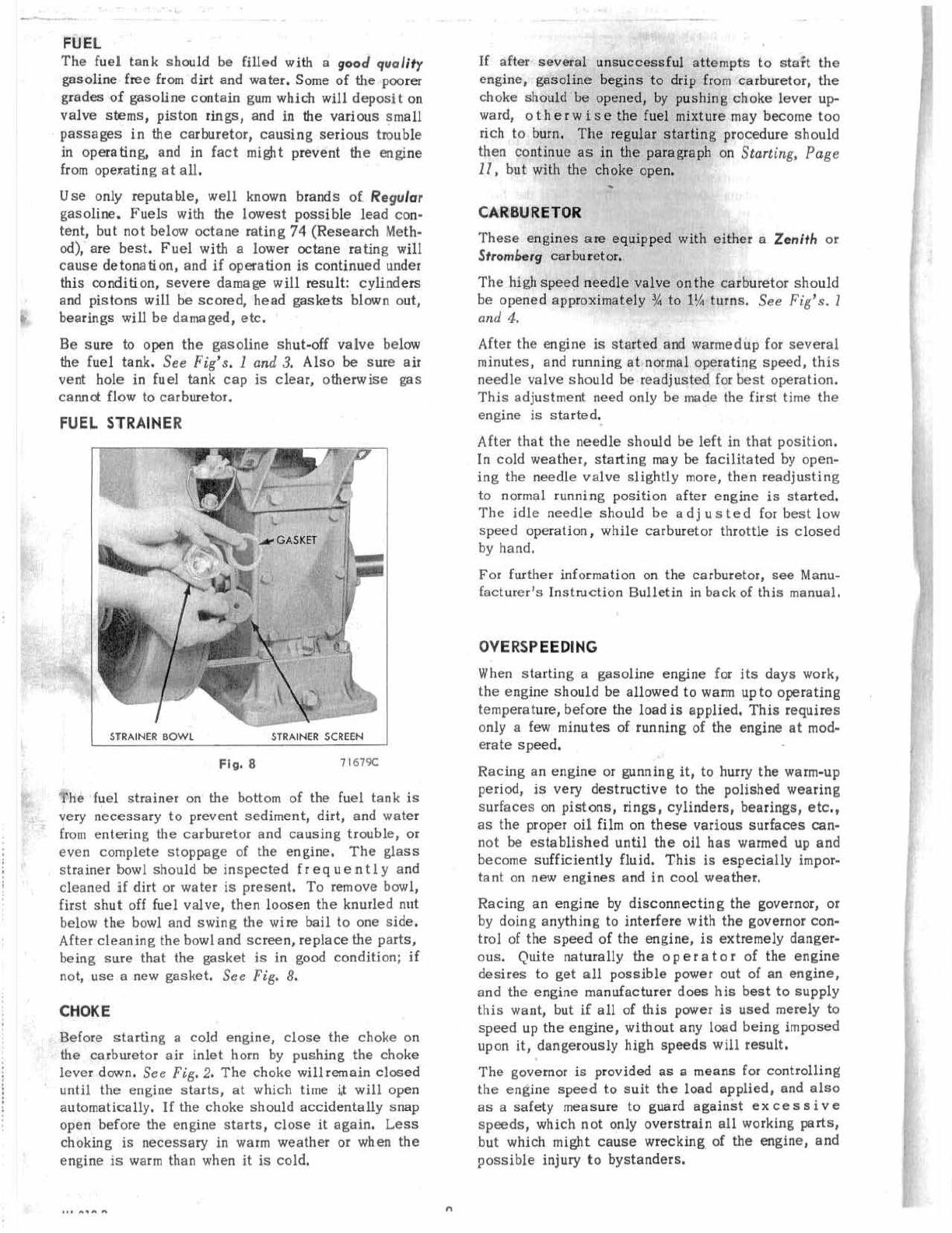
Fuel
Strainer
....
..
..............
..
.................. .................. 8
Governor
-
Adjustment
..
........
..
......................
..
....
22
Ignition
Switch
..
.................................................... 9
Ignition
Troubles
..................................................
14
Knocks
-
Engine
..
.... ...................................... ......
14
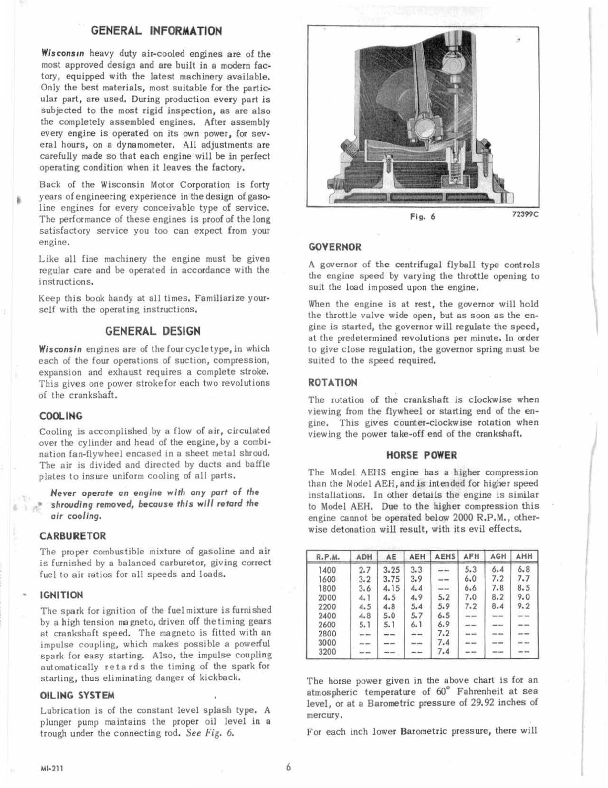
Lubrication
..
....
..
..
....
....
..
.... ....
..
.. .. ..
..
..
....
..
..
..
....
.. .. ..
7
Magneto .................................................................. 9
Magneto -lgn
it
ion Spark ..........................
..
.......... 9
Magneto-
Timing
..................................................
10
Magneto -
Drive
Shaft
and
Gear..............
..
..........
19
Oi
I - Grode
of
......................................................
..
7
Oil Pump ................................................
A..............
21
Over
speeding
.......................................................... 8
Overheats..
................................................
..
............ 14
Piston
and
Connecting
Rod..........
..
......................
16
Reduction
Gears
..
.............. ....
..
....
..
....
.... ................
24
Spark
Plug
...... ............................................
..
..........
10
Starting
-
Cronk
and
Rope
Starter
..........
..
..........
11
Starting
Difficulties
..
..
....
....
.. ..
.... ....
..
.................... 13
Stop
Engine
..
..
.... .. .. .. .. .. ....
..
..
..
.... ..
..
....
..
.. ..
..
....
........
11
Surging
or
Galloping....
..........................................
14
Valves
........................
..
....
....
................................
..
18
Valve
Tappet
Adjustment
....
..
..............................
19