Wise RS Series User manual

C-QIM-2731-T26_EN_Rev.1
Explosion proof
thermocouple & RTD
RS series
R920 series

1
C-QIM-2731-T26_EN_Rev.1
Contents
1. General items...................................................................................................................... 2
1.1 Introduction.........................................................................................................................2
1.2 Application.......................................................................................................................... 2
1.3 Warranty.............................................................................................................................2
2. Warning............................................................................................................................... 3
3. Main specs..........................................................................................................................4
3.1 Explosion-proof...................................................................................................................4
3.2 Protection grade.................................................................................................................4
3.3 Temperature sensor types .................................................................................................4
3.4 Accuracy and tolerances.................................................................................................... 4
4. Design................................................................................................................................. 6
4.1 Structure.............................................................................................................................6
4.1.1 Spring loaded type ..........................................................................................................6
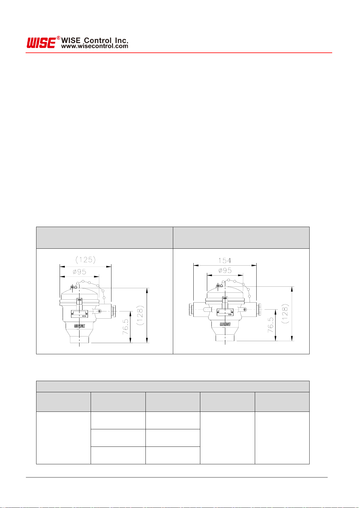
4.2 Head................................................................................................................................... 6
4.3 Detector unit and process connection unit material...........................................................7
4.4 Process connection unit..................................................................................................... 7
4.4.1 Sheathed cable (MI cable) type....................................................................................... 7
4.5 Relationship between process connection unit length and head temperature increase.... 8
5. Installation guide .................................................................................................................9
5.1 Pre-installation checks and precautions.............................................................................9
5.2 Installation requirement......................................................................................................9
6. Wiring ................................................................................................................................11
6.1 Extension & compensation wire....................................................................................... 11
6.1.1 Thermocouple(TC) ........................................................................................................11
6.1.2 Resistance thermometer detector(RTD)....................................................................... 11
6.2 Precaution for wiring.........................................................................................................12
6.3 Terminal block wiring........................................................................................................13
6.3.1 Thermocouple (TC) ....................................................................................................... 13
6.3.2 Resistance thermometer detector (RTD)...................................................................... 13
6.4 International color code table...........................................................................................14
7. Name plate........................................................................................................................15
7.1 Name plate indications..................................................................................................... 15
8. Repair and maintenance...................................................................................................16
9. Defect................................................................................................................................ 16
10.User’s duties......................................................................................................................17
11.Product return.................................................................................................................... 17

2
C-QIM-2731-T26_EN_Rev.1
1. General items
1.1 Introduction
WISE Control Inc. temperature sensors and thermowells are precisely fabricated according to
customer specifications. The RS series (R920) is an explosion-proof product designed as a spring
roded type to maximize heat transfer between the detector unit and thermowell. The products must be
tested and stored in appropriate locations, and the requirements provided in the documentation, test
reports and handling manuals, etc., must be adhered to in order to maintain optimum state during the
duration of use.
1.2 Application
Temperature sensors are used for temperature measurements in various processes. Measured values
are used for indication, recording and control in control panels or process systems. Depending on the
process situation, an appropriate thermowell may be selected and used, or a temperature sensor may
be inserted directly into a pipe without a thermowell. The thermowell is designed to protect a
thermometer or temperature sensor from fluid flow velocity, pressure and corrosion, etc., inside pipes.
The design prevents leakage of fluid from inside the pipe when a malfunctioning sensor is being
replaced. The user is responsible for selecting the appropriate thermowell for the process at hand.
WISE Control Inc. may provide advice when selecting products, but will not be held liable for mis-
selection of product.
1.3 Warranty
If one causes damage to the product due to failures to comply with the user manual, or if one
arbitrarily remodels it, changes or repairs the product, the manufacturer will not be responsible for it,
and the product warranty period will expire.

3
C-QIM-2731-T26_EN_Rev.1
2. Warning
Guide on handling for safe use
For the safe and correct use of the product, make sure to read the handling guide carefully before use.
Handling errors can cause device malfunctions, and it can lead to injury, accidents, etc.
Warning !
1) For the safety, only a worker with professional skills in electronics and electrical construction is
allowed to install the product
2) Make sure to use the product within the rated input/output range set in the specifications
3) Install the product in the environment of use indicated in the specifications.
4) Install wiring in accordance with the indoor wiring provisions and the Technical Standard for
Electrical Installations.
5) Make sure power has been cut off before performing wiring work.
6) Use wires with a sheath-insulated crimp terminal at the end.
7) Cable glands of the same explosion proof grade or higher.
8) Do not disassemble the product under any circumstances.
9) Use the product in the permissible temperature range.
10) Do not apply excessive loads, vibrations, or impacts.
11) When selecting a thermowell for the product, select a thermowell appropriate to the usage
conditions and environment.
12) The customer is responsible for mis-selection of thermowells.
13) Do not grab the head and turn it. Using a tool, hold the hexagonal screw parts to turn it.
14) O-ring can cause changes over time or characteristics change, and it can lead to a loss of
necessary functions for sealing, thus it requires periodic replacement, and in general, it is
recommended to replace it every 5 years.

4
C-QIM-2731-T26_EN_Rev.1
3. Main specs
3.1 Explosion-proof
Model: R920 (RS series)
Explosion-proofing grade: Ex d IIC T6
Ex tD A21 T85℃
Explosion-proofing technology: IEC 60079-0, IEC 60079-1, IEC 61241-0, IEC 61241-1
3.2 Protection grade
IP65
With thermowell : IP66, IP67
3.3 Temperature sensor types
Thermocouple (TC): K, E, J, T, N, B type
Resistance thermometer detector (RTD): Pt100Ωat 0℃
3.4 Accuracy and tolerances
Thermocouple (TC)
Class 1, Class 2 (DIN/IEC584-2, BS/EN60584-2, JIS C1602)
Special, Standard (ASTM E230, E988, ISA-MC96.1)
Resistance thermometer detector (RTD)
Class A : ± (0.15 + 0.002 l t l)
Class B : ± (0.3 + 0.005 l t l)
Please consult the table below for details.

5
C-QIM-2731-T26_EN_Rev.1
1) Thermocouple (TC): Class 1,2,3(IEC/EN 60584-2) or Standard / Special(ASTM E230, ANSI MC 96.1)
Type
Class
Temperature range
Maximum deviation
K
Standard
-200 ~ 0 ℃
The greater of ±2.2 ℃or ±2%
0 ~ 1260 ℃
The greater of ±2.2 ℃or ±0.75%
Special
0 ~ 1260 ℃
The greater of ±1.1 ℃or ±0.4%
E
Standard
-200 ~ 0 ℃
The greater of ±1.7 ℃or ±1%
0 ~ 870 ℃
The greater of ±1.7 ℃or ±0.5%
Special
0 ~ 870 ℃
The greater of ±1.0 ℃or ±0.4%
B
Standard
870 ~ 1700 ℃
±0.5%
Special
870 ~ 1700 ℃
±0.25%
R
Standard
0 ~ 1480 ℃
The greater of ±1.5 ℃or ±0.25%
Special
0 ~ 1480 ℃
The greater of ±0.6 ℃or ±0.1%
S
Standard
0 ~ 1480 ℃
The greater of ±1.5 ℃or ±0.25%
Special
0 ~ 1480 ℃
The greater of ±0.6 ℃or ±0.1%
N
Standard
0 ~ 1260 ℃
The greater of ±2.2 ℃or ±0.75%
Special
0 ~ 1260 ℃
The greater of ±1.1 ℃or ±0.4%
T
Standard
-200 ~ 0 ℃
The greater of ±1.0 ℃or ±1.5%
0 ~ 370 ℃
The greater of ±1.0 ℃or ±0.75%
Special
0 ~ 370 ℃
The greater of ±0.5 ℃or ±0.4%
J
Standard
0 ~ 760 ℃
The greater of ±2.2 ℃or ±0.75%
Special
0 ~ 760 ℃
The greater of ±1.1 ℃or ±0.4%
*Note.
Each model has different certification types. See “3.3 Temperature sensor types” and look up the
certifications for the applicable type in the table.
2) Resistance thermometer detector (RTD): Class A, B (IEC/EN 60751)
Tolerance
class
Temperature range of validity (°C)
Tolerance value (℃)
For wire wound resistors
For film resistors
A
-100 to +450
-30 to +300
± ( 0.15 + 0.002 | t | )
B
-196 to +600
-50 to +500
± ( 0.3 + 0.005 | t | )

6
C-QIM-2731-T26_EN_Rev.1
4. Design
4.1 Structure
4.1.1 Spring loaded type
In the spring-loaded type, a spring is installed inside the head, and the load from the spring allows the
sensor to maintain maximum contact. Detection response time is faster compared to the basic type.
Spring-loaded type sensors are not sealed to allow for movement of the detector unit, and are typically
installed together with a thermowell appropriate to the use environment. When installing the
temperature sensor directly, contact between the process fluid and temperature sensor should be
avoided, or a sealed type sensor should be used instead.
4.2 Head
Warning: Certified explosion proof cable glands must be used when installing in hazardous areas. See
the <Table: Head information> below for the types of cables that may be connected.
Table : Head information
Head
Head material
Head thread
(Cable entry size)
Conduit adaptor
Conduit adaptor
material
Explosion proof
(Single/Dual entry
type)
ALDC12.1
(Single entry)
PF 1/2, PF 3/4,
NPT 1/2, NPT 3/4
NPT 1/2, NPT 3/4
M20x1.5P
PT (unavailable)
Brass+Ni.plating
316SS
316SS
PF 1/2
AC4C
(Dual entry)
PF 1/2
Explosion proof
(Single entry)
Explosion proof
(Double entry)

7
C-QIM-2731-T26_EN_Rev.1
4.3 Detector unit and process connection unit material
Metal
Material
Usage
temperature
(℃)
Max.
temperature
(℃)
Characteristic
304SS
900
1000
Typically used in thermowells to protect against heat and
corrosion. Direct use in sulfurous environments or
reducing flame is not recommended.
316SS
900
1000
Contains Mo for outstanding heat, acid and alkaline
resistance.
316L SS
950
1050
Less carbon content than 316.
Better acid and alkaline resistance than 316SS.
321SS
900
1000
Weak sulfur and reducing heat resistance. Outstanding
corrosion and heat resistance
310SS
950
1050
High Ni and Cr content, with optimal high-temperature
strength with high heat and oxidation resistance.
347SS
900
1000
Contains Nb-Ta for better corrosion resistance than
304SS. Outstanding resistance to fine surface corrosion.
446SS
1050
1125
High Cr steel with outstanding resistance to oxidizing and
reducing atmospheres containing sulfur. Suitable for salt
baths, castings and other high-temperature
environments.
Inconel600
1180
1250
High Cr and Ni steel with outstanding resistance to
oxidizing and reducing atmospheres at high temperature.
Cannot be used in sulfurous atmospheres.
4.4 Process connection unit
4.4.1 Sheathed cable (MI cable) type

8
C-QIM-2731-T26_EN_Rev.1
4.5 Relationship between process connection unit length and head temperature
increase
1) T: Operating temperature)
2) Process extension length: Distance between thermowell or process line to
* The process extension length of units installed in explosion proof areas must be sufficient to keep the
temperature increase at less than 20°C
※Caution: When installing a temperature sensor unit to satisfy the surface temperature condition (T6:
85℃), please proceed according to the figure below

9
C-QIM-2731-T26_EN_Rev.1
5. Installation guide
5.1 Pre-installation checks and precautions
1) Beware of disconnection of the lead wire during storage and transport.
2) Check for disconnection using a tester prior to installation of the product.
3) Use a Megger (Megohmmeter) to measure and confirm that insulation resistance is within normal
range prior to installation of the product.
4) When transporting the sensor assembly to the tank and attaching to the nozzle, avoid applying
external physical force (compression, impact, etc.) on the sheathed cable (MI cable).
5) Check that the protection cover and thermocouple are free of scratches, cut marks, oil or other
contaminants.
(Even tiny amounts of foreign matter can decrease the accuracy of measurements.)
5.2 Installation requirement
1) Do not pull on or push the sheathed cable (MI cable) when installing or disassembling the product.
2) For products attached to comp’ fittings do not loosen screws during operation. Attach the comp’
fittings to the temperature sensor prior to installation.
3) For products attached to comp’ fittings, be careful not to pull or turn the sheathed cable (MI cable)
when attaching or detaching components with the product in an assembled state. (Can be the
cause of leaks)
4) When installing a temperature sensor in an existing thermowell, inspect the inside of the
thermowell for obstructions before inserting the temperature sensor to prevent damage to the
temperature sensor or sparks due to friction during installation.
5) When installing in direct contact with the process, check that the external loads applied to not
cause deformation of the instrumentation and welded parts

10
C-QIM-2731-T26_EN_Rev.1
6) Additional load and vibration from other elements of the plant can impact the operation of sensor
components. Load from installation in areas with vibration may damage the operation of the
sensor element.
7) The end user must ensure that the instrumental has been appropriately installed so that the
allowed limits are not exceeded.
*Note.
Please consult the thermowell manual for temperature sensor installation conditions and installation
locations.

11
C-QIM-2731-T26_EN_Rev.1
6. Wiring
6.1 Extension & compensation wire
This type of cable used for temperature measurement.A wire of the same material (extension) as the
thermocouple(TC) or a material having thermoelectric power characteristics as the thermocouple(TC)
is extended to the terminal of the instrument. A compensation wire provides the same temperature
compensation effect as an extension of the thermocouple(TC). Depending on the use environment
and conditions, different insulation and sheathing materials may be used, including low-temperature,
high-temperature, humidity-resistant, oil-resistant, and flex-resistant materials.
6.1.1 Thermocouple(TC)
The wire is made of the same material as the thermocouple(TC), and indicates the same
temperature measurement as the thermocouple(TC).
Temperature is measured using the change in voltage (㎶) according to temperature changes.
Therefore, sufficient consideration must be given to voltage drop when selecting the unit.
6.1.2 Resistance thermometer detector(RTD)
Temperature is measured using the change in resistance (Ω) according to temperature.
Resistance thermometer detector (RTD) cables are selected as 3-wire or 4-wire, and one end of
the shielding wire must be grounded.
Type
Conductor
Insulator
Shielding
Thermocouple (TC)
By thermocouple
type
Glass braiding
Tinned braided wire
Teflon
Teflon
Vinyl (PVC)
Vinyl (PVC)
Resistance
thermometer detector
(RTD)
Tinned copper wire
Glass braiding
Tinned braided wire
Teflon
Tinned braided wire
Vinyl (PVC)
Vinyl (PVC)
1) Extension & compensation wire having specs appropriate for measuring temperature sensor
signals must be selected and used.
2) Voltage flow must be given consideration when deciding cable thickness.

12
C-QIM-2731-T26_EN_Rev.1
3) The external covering material must be selected appropriately for the installation environment.
4) If there are outdoor wiring sections, do not use glass sheathing. Humidity may reduce insulation
resistance and cause measuring errors.
5) Cables shall be protected from damage such as breakage or cutting by the surrounding
environment.
6) Exercise caution to prevent folding or knitting of cable.
6.2 Precaution for wiring
1) Make sure to cut off power before wiring product with an explosion proof grade.
2) Connect thermocouples (TC) after checking polarity (+/-). Wire resistance temperature detectors
(RTD) after disconnecting the A/B/B (3-wire) terminal.
3) Attach the end of the compensation wire and cable to the terminal block using crimp terminals.
Tightly fasten the screws.
4) When wiring to a transmitter, adhere to the wiring instructions given in the user manual for the
transmitter.
5) For equipment with an explosion proof grade, make sure the cover does not open during
operation. Tighten the locking apparatus.
6) Earthing
- Use aluminum earthing terminals to prevent corrosion.
- Use 304SS earthing bolts.
- Use spring washers to prevent loosening of the earthing terminals.
- When using external earthing terminals, check the connectors and use an appropriate earthing
line.
7) After making the connections, inspect to ensure that the power supply and signal cables have
been connected properly.

13
C-QIM-2731-T26_EN_Rev.1
6.3 Terminal block wiring
6.3.1 Thermocouple (TC)
6.3.2 Resistance thermometer detector (RTD)
Single (2-Wire)
Double (4-Wire)
Single (3-Wire)
Double (6-Wire)
Single (4-Wire)
Double (8-Wire)

14
C-QIM-2731-T26_EN_Rev.1
6.4 International color code table
See the table below when connecting the product.
(Different colors may be used according to customer requirements.)
Thermocouple(TC)
Type
EN (IEC 60584-3)
ANSI(ISA MC96.1)
JIS C 1610 (KS C 1609)
(+)
(-)
(+)
(-)
(+)
(-)
T
Brown
White
Blue
Red
Red
White
E
Violet(Purple)
White
Purple
Red
Red
White
J
Black
White
White
Red
Red
White
K
Green
White
Yellow
Red
Red
White
N
Pink
White
Orange
Red
Red
White
B
Grey
White
Grey
Red
Red
White
R
Orange
White
Black
Red
Red
White
S
Orange
White
Black
Red
Red
White
Resistance thermometer detector (RTD)
IEC/EN 60751 standard applied (see applicable colors for the KS C 1603 standard)
Single (3-Wire)
Double (6-Wire)
Single (4-Wire)
Double (8-Wire)

15
C-QIM-2731-T26_EN_Rev.1
7. Name plate
Certified explosion proof products have passed confirmation testing, and have the same specs as
submitted to the certification lab.
The model name is subject to change depending on explosion proof rating certification.
7.1 Name plate indications
Explosion-proofing structure and grade: Ex d IIC T6 IP65 (Ex d)
Ex tD A21 T85℃IP65 (Ex tD)
Ambient temperature conditions: -20 ℃≤Ta ≤60 ℃
-25 ℃≤Ta ≤60 ℃(Ex tD)
Stable certification mark and certification information (certification number, certification body,
certification date) are separately specified on the nameplate.
Warning: Do not open when an explosive atmosphere may be present.
Tag No. (Identification number)
KCs Ex d
KTL Ex tD (Single conduit)
KTL Ex tD (Double conduit)
2022 Deogyeong-daero,Giheung-gu,Yongin-si,Gyeonggi-do,Korea
WISE CONTROL INC.
Tag No.
WARNING - DO NOT OPEN WHEN AN EXPLOSIVE DUST ATMOSPHERE MAY BE PRESENT
TYPE : R92X(Single conduit)
Certificate No. : 20-KA2BO-0705X
Ex tD A21 T85°C IP65
(Tamb = -25°C to +60°C)
Certificate issued by : Korea Testing Laboratory
Date of Certificate : 2020.09.02
Tag No.
WARNING - DO NOT OPEN WHEN AN EXPLOSIVE DUST ATMOSPHERE MAY BE PRESENT
TYPE : R92X(Double conduit)
Certificate No. : 20-KA2BO-0706X
Ex tD A21 T85°C IP65
(Tamb = -25°C to +60°C)
Certificate issued by : Korea Testing Laboratory
Date of Certificate : 2020.09.02
2022 Deogyeong-daero,Giheung-gu,Yongin-si,Gyeonggi-do,Korea
WISE CONTROL INC.

16
C-QIM-2731-T26_EN_Rev.1
8. Repair and maintenance
Temperature sensors typically do not require maintenance. Only skilled personnel may carry out
maintenance and repair activities when necessary, and Wise Co., Ltd. may provide support for
maintenance and repair.
Repairs
Repairs may be carried out only by Wise Co., Ltd. or a component manufacturer.
Calibration
The accuracy of a temperature sensor may be confirmed through comparative measurements.
Accuracy must be maintained through checks performed at regular intervals. Testing and calibration
must be carried out using suitable test equipment, and by qualified personnel.
Wise Co., Ltd may provide calibration services.
9. Defect
If the defect cannot be removed through the measures listed above, immediately shut down the
equipment. Confirm that all pressure has been released and no signal is output, and protect the
equipment to prevent restarting. In this case, please contact the manufacturer.
If it is necessary to return the equipment, please follow the instructions in Chapter 11, “Returns”.
Defect
Cause
Response
Damaged line and no
signal
Excessive mechanical load or
overheating
Replace with sensor unit of
appropriate structure
Inaccurate
measurement
Overheat, or decreased sensor
accuracy due to overheating of
chemical substances
Use thermowell
Signal interference
Drift current due to ground loop or
electrical field
Used shielded connection cable,
increase distance from motor and
power line
Remove electric potential and use
galvanic insulated transmitter or
barrier
Long response time
Improper installation location
Adjust process line installation
location or insertion depth
Inappropriate thermowell size
Select thermowell with dimensions
usable with the process line
Corrosion
Improper material selected for
inserted components or thermowell
Select material compatible with
process

17
C-QIM-2731-T26_EN_Rev.1
10. User’s duties
Temperature sensor products are used in high temperatures and corrosive environments. The right
product must be selected based on various safety considerations. For all temperature sensors designs,
proper installation is the most important.
Incorrect installation can eventually lead to an inaccurate reading of temperature.
Wise Co., Ltd. can support users’ selection but will not be responsible for them in any sort of way.
11. Product return
1) If the product gets returned for recalibration or repair work, make sure to use the original
packaging or safe packaging method, and also make sure to return the related documents.
2) Make sure to prevent exposures of the product to dust, wetness, or other sources of pollution
during the conveyance.
3) Pack it properly to prevent vibration or any kind of impact during the conveyance.
4) If the product gets damaged during the conveyance, make sure to record it on paper, and if there
is some kind of loss due to a delayed installation, one may demand compensation from the
conveyance company.

18
C-QIM-2731-T26_EN_Rev.1
The content of the user manual is prepared with the best efforts, but it might contain typos, or errors requiring fixes,
so we kindly ask for understanding. The product spec or exterior can be changed without a pre-notice for the quality
improvement purposes, thus Wise Co., Ltd. has the rights to change them. Figures used in the user manual are for
just illustration purposes, and they can differ from the actual shapes
Yongin Factory
2022 Deogyeong-daero,Giheung-
gu,Yongin-si,Gyeonggi-do (Sanggal-
dong )
www.wisecontrol.com
A/S related Inquiries
2022 Deogyeong-daero,Giheung-
gu,Yongin-si,Gyeonggi-do (Sanggal-
dong)
Home page: Service
center>Technology/Quote Inquiry
Wise Co., Ltd. Seoul Office
181, Gasan digital 1-ro, Geumcheon-gu,
Seoul (Gasan-dong, Gasan W CENTER)
F19
T. 02-300-2300
F. 02-300-2400

C-QIM-2731-T26_KR_Rev.2
Tel +82-2-300-2300
Fax +82-2-300-2400
webmaster@wisecontrol.com
Explosion proof
thermocouple & RTD
RS series
R920 series
This manual suits for next models
1
Table of contents
Other Wise Industrial Equipment manuals
Popular Industrial Equipment manuals by other brands

Indutherm
Indutherm VC 400 LCD instruction manual

MICRO-EPSILON
MICRO-EPSILON ELTROTEC Endolight FOT Halogen 150 instruction manual

Branick
Branick 5500 Installation, Operation and Repair Parts Information

TUFFA TANKS
TUFFA TANKS 30000VBFS Installation, operation and servicing manual

Siemens
Siemens APACS+ Installation and service instruction

STAUFF
STAUFF RH Series Translation of the original operating instructions