Wisi MULTISYSTEM DY 64 1810 User manual

-1-
Betriebsanleitung
Operating instructions
411 883 b
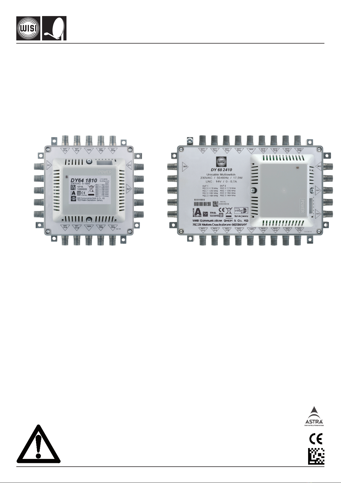
WISI MULTISYSTEM QUICK
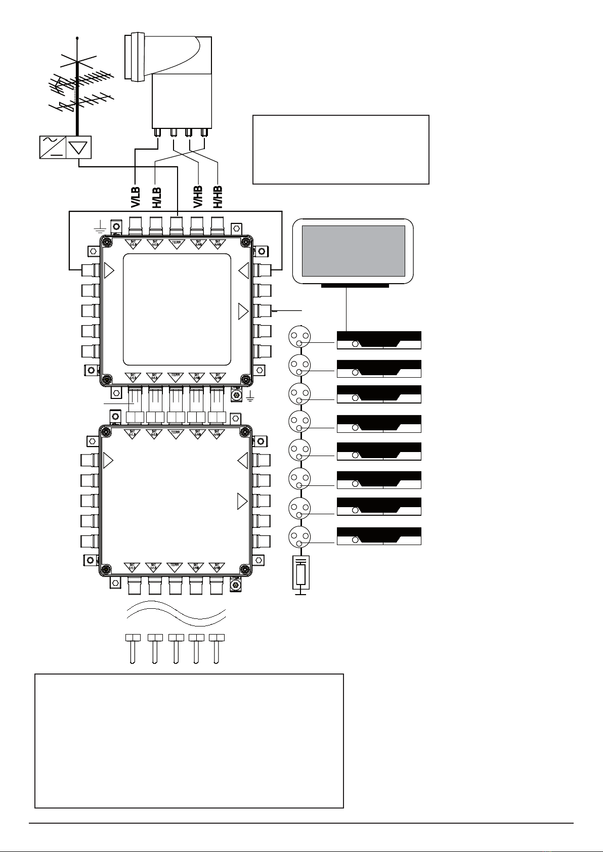
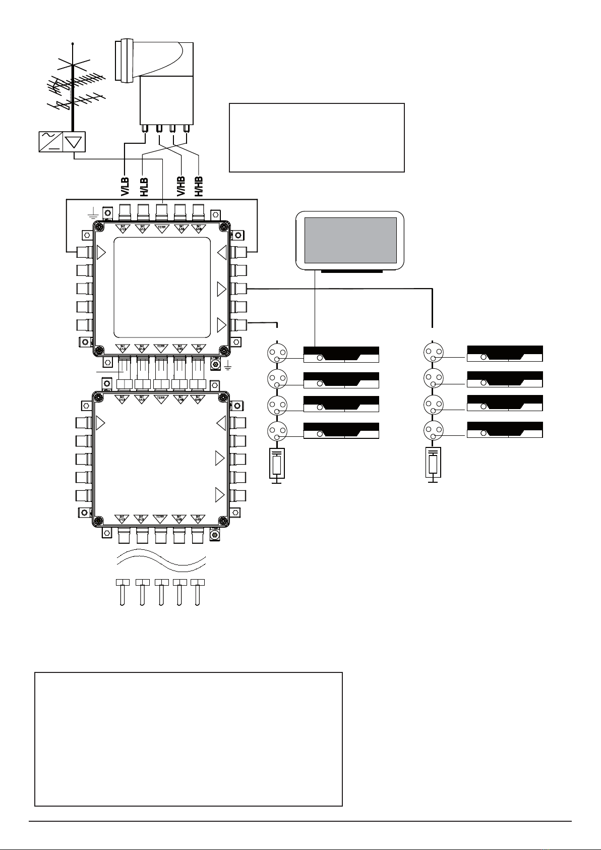
DY 64 1810 / 2410 Stand alone + Kaskade
DY 64 1800 / 2400 Stand alone + Cascade
DY 64 1800 / 1810
4 SAT-Eingänge + 1 TERR / 4 SAT inputs+1 TERR
1 UNICABLE-Ausgang / 1 UNICABLE output
DY 64 2400 / 2410
4 SAT-Eingänge + 1 TERR / 4 SAT inputs+1 TERR
2 UNICABLE-Ausgänge / 2 UNICABLE outputs
Kaskadierbare Einkabellösung
4x Sat, 1x Terr (Stamm)
Einzeln und in Kaskade
Kompatibel mit DY50A, DY48A/46A/44A,
DY58B/56B, DY16/12
EN50494 konform - Einkabelstandard
Konstanter Ausgangspegel
DY 64 1800/1810 90 dBµV
DY 64 2400/2410 85 dBµV
Cascadable single cable switching unit
4x Sat, 1x Terr trunk lines
Stand alone and in cascade
Compatible with DY50A, DY48A/46A/44A,
DY58B/56B, DY16/12
Conform to the EN50494 single cable standard
Fixed output level
DY 64 1800/1810 90 dBµV
DY 64 2400/2410 85 dBµV
IES-tauglich
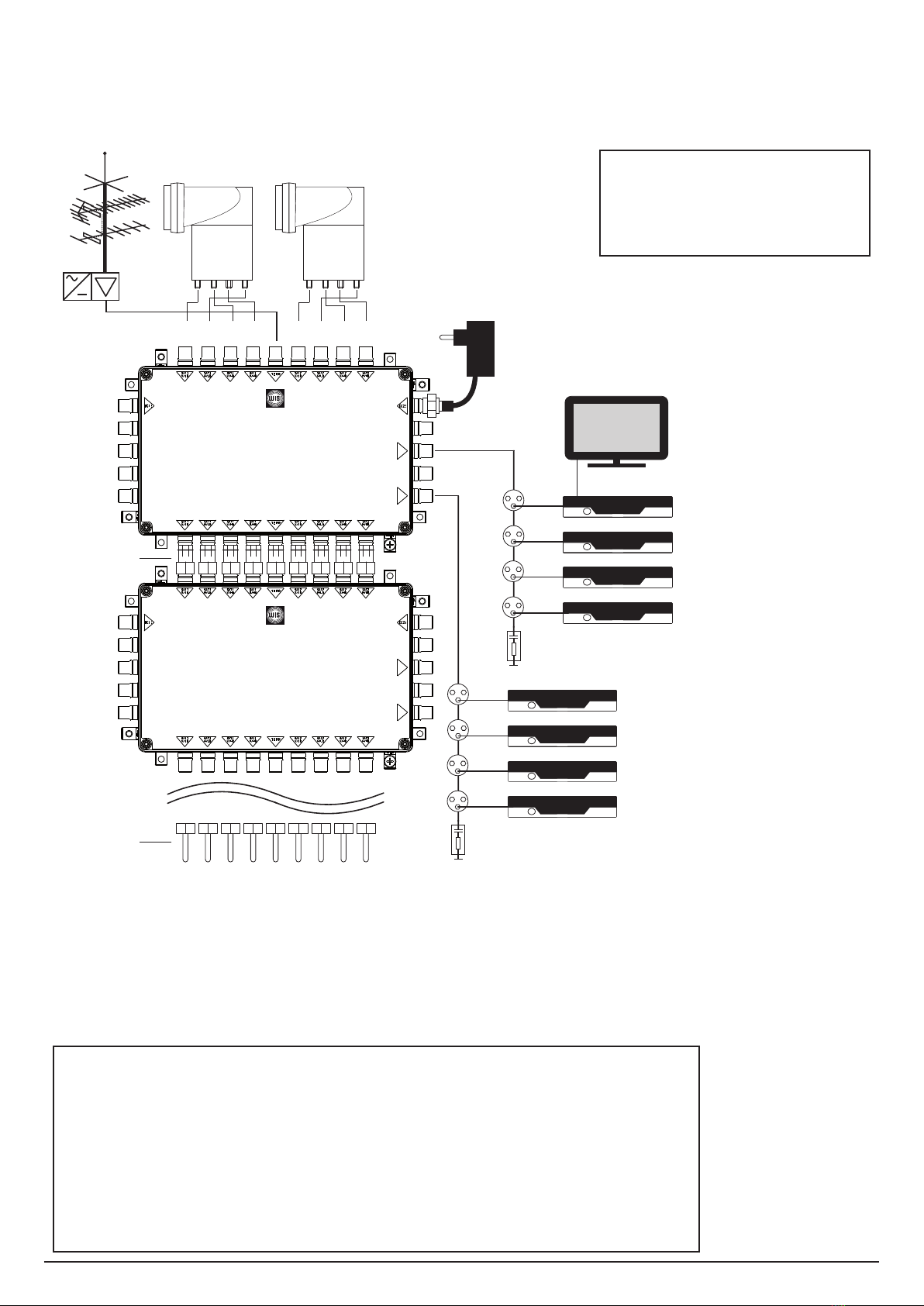
DY 68 1810 / 2410 Stand alone + Kaskade
DY 68 1800 / 2400 Stand alone + Cascade
DY 68 1800 / 1810
8 SAT-Eingänge + 1 TERR / 8 SAT inputs+1 TERR
1 UNICABLE-Ausgang / 1 UNICABLE output
DY 68 2400 / 2410
8 SAT-Eingänge + 1 TERR / 8 SAT inputs+1 TERR
2 UNICABLE-Ausgänge / 2 UNICABLE outputs
Kaskadierbare Einkabellösung
8x Sat, 1x Terr (Stamm)
Einzeln und in Kaskade
Kompatibel mit DY90, DY04/06/08,
DY94A/96A/98A
EN50494 konform - Einkabelstandard
Konstanter Ausgangspegel
DY 68 1800/1810 90 dBµV
DY 68 2400/2410 85 dBµV
Cascadable single cable switching unit
8x Sat, 1x Terr trunk lines
Stand alone and in cascade
Compatible with DY90, DY04/06/08,
DY94A/96A/98A
Conform to the EN50494 single cable standard
Fixed output level
DY 68 1800/1810 90 dBµV
DY 68 2400/2410 85 dBµV
Erdung bzw. Potentialausgleich!
Nach EN 50 083-1 muß die Satelliten-Antennenanlage den Sicherheitsanforderungen
wie z.B. Erdung, Potentialausgleich entsprechen.
Grounding and Potential Equalization
Pursuant to EN 50 083-1 the satellite antenna system must comply with safety
requirements, i.e., grounding and potential equalization.

-2-
DY 64 1800
DC1 DC2
OUT
DY 64 1810
230 VAC
DC1 DC2
OUT
OC 04
L/V (DC)
L/H (DC)
H/H (DC)
H/V (DC)
1 x DV 27
8 x DB 64
TV
5 x DV 49
5 x DV 25
VS...
FM,
DVB-T
OUT
8 x OR 5x Rec. - Frequenz - Kanal ID
8 - 1892 MHz - 7
7 - 1790 MHz - 6
6 - 1688 MHz - 5
5 - 1586 MHz - 4
4 - 1484 MHz - 3
3 - 1382 MHz - 2
2 - 1280 MHz - 1
1 - 1178 MHz - 0
Stammausgänge abschließen
Terminate trunk outputs
Jedem Receiver muss die Frequenz
und Kanal ID zugeordnet werden.
Set frequency and Ch ID for each
receiver.
DY 64 1810 / DY 64 2410
Versorgung über internes Netzteil
Supply by internal power-supply
Verbindung DC 1 mit DC 2 über F-Kabel: Standby aus
Connect DC 1 with DC 2 via F-Cable: Standby off
Bei Kaskadierung Standby ausser Betrieb nehmen!
If cascading-switch off standby!
Legende
V / LB = Vertical / Low Band
H / LB = Horizontal / Low Band
V / HB = Vertical / High Band
H / HB = Horizontal / High Band

-3-
DY 64 1800
DC1 DC2
OUT
DY 64 1800
DC1 DC2
OUT
OC 04
L/V (DC)
L/H (DC)
H/H (DC)
H/V (DC)
1 x DV 27
8 - 1892 MHz - 7
7 - 1790 MHz - 6
6 - 1688 MHz - 5
5 - 1586 MHz - 4
4 - 1484 MHz - 3
3 - 1382 MHz - 2
2 - 1280 MHz - 1
1 - 1178 MHz - 0
8 x OR 5x
5 x DV 49
5 x DV 25
VS...
FM,
DVB-T
DY 55
8 x DB 64
OUT
Rec. - Frequenz - Kanal ID
TV
Jedem Receiver muß die Frequenz
und Kanal ID zugeordnet werden.
Set frequency and Ch ID for each
receiver.
Stammausgänge abschließen
Terminate trunk outputs
DY 64 1800 / DY 64 2400
Versorgung mit Netzteil DY 55
Supply by power-supply DY 55
DC 1: Einspeisung mit Standbyfunktion / Supply for standby
DC 2: Einspeisung ohne Standbyfunktion / Supply without standby function
Bei Kaskadierung Standby ausser Betrieb nehmen!
If cascading-switch off standby!
Legende
V / LB = Vertical / Low Band
H / LB = Horizontal / Low Band
V / HB = Vertical / High Band
H / HB = Horizontal / High Band

-4-
DY 64 2400
DC1 DC2
DY 64 2410
230 VAC
DC1 DC2
OUT1
OC 04
L/V (DC)
L/H (DC)
H/H (DC)
H/V (DC)
1 x DV 27
4 x DB 64
TV
5 x DV 49
5 x DV 25
VS...
FM,
DVB-T
OUT2
OUT 1
1 x DV 27
4 x OR 5x
REC 4
REC 3
REC 2
REC 1
OUT 2
OUT2
OUT1
4 x OR 5x
OUT2
Rec. - Frequenz - Kanal ID
OUT1
Rec. - Frequenz - Kanal ID
4 x DB 64
4 - 1484 MHz - 3
3 - 1382 MHz - 2
2 - 1280 MHz - 1
1 - 1178 MHz - 0
4 - 1484 MHz - 3
3 - 1382 MHz - 2
2 - 1280 MHz - 1
1 - 1178 MHz - 0
Jedem Receiver muß die Frequenz
und Kanal ID zugeordnet werden.
Set frequency and Ch ID for each
receiver.
DY 64 1810 / DY 64 2410
Versorgung über internes Netzteil
Supply by internal power-supply
Verbindung DC 1 mit DC 2 über F-Kabel: Standby aus
Connect DC 1 with DC 2 via F-Cable: Standby off
Bei Kaskadierung Standby ausser Betrieb nehmen!
If cascading-switch off standby!
Stammausgänge abschließen
Terminate trunk outputs
Legende
V / LB = Vertical / Low Band
H / LB = Horizontal / Low Band
V / HB = Vertical / High Band
H / HB = Horizontal / High Band

-5-
DY 64 2400
DC1 DC2
DY 64 2400
DC1 DC2
OUT1
OC 04
L/V (DC)
L/H (DC)
H/H (DC)
H/V (DC)
1 x DV 27
4 x DB 64
TV
5 x DV 49
5 x DV 25
VS...
FM,
DVB-T
OUT2
OUT 1
1 x DV 27
REC 4
REC 3
REC 2
REC 1
OUT 2
4 x OR 5x
OUT2
OUT1
4 x OR 5x
4 - 1484 MHz - 3
3 - 1382 MHz - 2
2 - 1280 MHz - 1
1 - 1178 MHz - 0
OUT2
Rec. - Frequenz - Kanal ID
4 - 1484 MHz - 3
3 - 1382 MHz - 2
2 - 1280 MHz - 1
1 - 1178 MHz - 0
OUT1
Rec. - Frequenz - Kanal ID
4 x DB 64
DY 55
Legende
V / LB = Vertical / Low Band
H / LB = Horizontal / Low Band
V / HB = Vertical / High Band
H / HB = Horizontal / High Band
Jedem Receiver muß die Frequenz
und Kanal ID zugeordnet werden.
Set frequency and Ch ID for each
receiver.
Stammausgänge abschließen
Terminate trunk outputs
DY 64 1800 / DY 64 2400
Versorgung mit Netzteil DY 55
Supply by power-supply DY 55
DC 1: Einspeisung mit Standbyfunktion / Supply for standby
DC 2: Einspeisung ohne Standbyfunktion / Supply without standby function
Bei Kaskadierung Standby ausser Betrieb nehmen!
If cascading-switch off standby!

-6-
OUT 1
DY 68 1800
OUT 1
DY 68 1810 TV
8 - 1892 MHz - 7
7 - 1790 MHz - 6
6 - 1688 MHz - 5
5 - 1586 MHz - 4
4 - 1484 MHz - 3
3 - 1382 MHz - 2
2 - 1280 MHz - 1
1 - 1178 MHz - 0
Rec. - Frequenz - Kanal ID
1x DV 27
8x OR xx
OUT
FM,
DVB-T
5x DV 49 A
5x DV 25
V/LB
H/LB
V/HB
H/HB
V/LB
H/LB
V/HB
H/HB
OC 04
L/V (DC)
L/H (DC)
H/H (DC)
H/V (DC)
OC 04
L/V (DC)
L/H (DC)
H/H (DC)
H/V (DC)
VS...
Stammausgänge abschließen
Terminate trunk outputs
Jedem Receiver muss die Frequenz
und Kanal ID zugeordnet werden.
Set frequency and Ch ID for each
receiver.
DY 68 1810 / DY 68 2410
Versorgung über internes Netzteil
Supply by internal power-supply
Verbindung DC 1 mit DC 2 über F-Kabel: Standby aus
Connect DC 1 with DC 2 via F-Cable: Standby off
Bei Kaskadierung Standby ausser Betrieb nehmen!
If cascading-switch off standby!
Legende
V / LB = Vertical / Low Band
H / LB = Horizontal / Low Band
V / HB = Vertical / High Band
H / HB = Horizontal / High Band

-7-
OUT 1
DY 68 1800
OUT 1
DY 68 1800 TV
8 - 1892 MHz - 7
7 - 1790 MHz - 6
6 - 1688 MHz - 5
5 - 1586 MHz - 4
4 - 1484 MHz - 3
3 - 1382 MHz - 2
2 - 1280 MHz - 1
1 - 1178 MHz - 0
Rec. - Frequenz - Kanal ID
V/LB
H/LB
V/HB
H/HB
V/LB
H/LB
V/HB
H/HB
OC 04
L/V (DC)
L/H (DC)
H/H (DC)
H/V (DC)
OC 04
L/V (DC)
L/H (DC)
H/H (DC)
H/V (DC)
VS...
5x DV 49 A
5x DV 25
1x DV 27
8x OR xx
OUT
1x DY 55
FM,
DVB-T
Jedem Receiver muß die Frequenz
und Kanal ID zugeordnet werden.
Set frequency and Ch ID for each
receiver.
Stammausgänge abschließen
Terminate trunk outputs
DY 68 1800 / DY 68 2400
Versorgung mit Netzteil DY 55
Supply by power-supply DY 55
DC 1: Einspeisung mit Standbyfunktion / Supply for standby
DC 2: Einspeisung ohne Standbyfunktion / Supply without standby function
Bei Kaskadierung Standby ausser Betrieb nehmen!
If cascading-switch off standby!
Legende
V / LB = Vertical / Low Band
H / LB = Horizontal / Low Band
V / HB = Vertical / High Band
H / HB = Horizontal / High Band

-8-
Jedem Receiver muß die Frequenz
und Kanal ID zugeordnet werden.
Set frequency and Ch ID for each
receiver.
DY 68 1810 / DY 68 2410
Versorgung über internes Netzteil
Supply by internal power-supply
Verbindung DC 1 mit DC 2 über F-Kabel: Standby aus
Connect DC 1 with DC 2 via F-Cable: Standby off
Bei Kaskadierung Standby ausser Betrieb nehmen!
If cascading-switch off standby!
Stammausgänge abschließen
Terminate trunk outputs
OUT 1
OUT 2
DY 68 2400
OUT 1
OUT 2
DY 68 2410
V/LB
H/LB
V/HB
H/HB
V/LB
H/LB
V/HB
H/HB
OC 04
L/V (DC)
L/H (DC)
H/H (DC)
H/V (DC)
OC 04
L/V (DC)
L/H (DC)
H/H (DC)
H/V (DC)
VS...
4 - 1484 MHz - 3
3 - 1382 MHz - 2
2 - 1280 MHz - 1
1 - 1178 MHz - 0
Rec. - Frequenz - Kanal ID
4 - 1484 MHz - 3
3 - 1382 MHz - 2
2 - 1280 MHz - 1
1 - 1178 MHz - 0
Rec. - Frequenz - Kanal ID
OUT 1
OUT 1
OUT 2
OUT 2
1x DV 27
1x DV 27
TV
4x OR xx
5x DV 49 A
5x DV 25
Legende
V / LB = Vertical / Low Band
H / LB = Horizontal / Low Band
V / HB = Vertical / High Band
H / HB = Horizontal / High Band

-9-
OUT 1
OUT 2
DY 68 2400
OUT 1
OUT 2
DY 68 2400
4 - 1484 MHz - 3
3 - 1382 MHz - 2
2 - 1280 MHz - 1
1 - 1178 MHz - 0
Rec. - Frequenz - Kanal ID
4 - 1484 MHz - 3
3 - 1382 MHz - 2
2 - 1280 MHz - 1
1 - 1178 MHz - 0
Rec. - Frequenz - Kanal ID
V/LB
H/LB
V/HB
H/HB
V/LB
H/LB
V/HB
H/HB
OC 04
L/V (DC)
L/H (DC)
H/H (DC)
H/V (DC)
OC 04
L/V (DC)
L/H (DC)
H/H (DC)
H/V (DC)
VS...
OUT 1
OUT 1
OUT 2
OUT 2
1x DV 27
1x DV 27
TV
4x OR xx
1x DY 55
FM,
DVB-T
5x DV 49 A
5x DV 25
Legende
V / LB = Vertical / Low Band
H / LB = Horizontal / Low Band
V / HB = Vertical / High Band
H / HB = Horizontal / High Band
Jedem Receiver muß die Frequenz
und Kanal ID zugeordnet werden.
Set frequency and Ch ID for each
receiver.
Stammausgänge abschließen
Terminate trunk outputs
DY 68 1800 / DY 68 2400
Versorgung mit Netzteil DY 55
Supply by power-supply DY 55
DC 1: Einspeisung mit Standbyfunktion / Supply for standby
DC 2: Einspeisung ohne Standbyfunktion / Supply without standby function
Bei Kaskadierung Standby ausser Betrieb nehmen!
If cascading-switch off standby!

-10-
Technische Daten / Specifications
DY 64 1800 / DY 64 1810
Stamm / Trunk 4+1
Frequenzbereich / Frequency range SAT 950-2400 MHz
Durchgangsdämpfung / Through loss SAT 1,3-1,6 dB
Eingangspegel / Input level SAT 60-90 dBµV
Isolation Stamm / Isolation trunk SAT 35 dB min.
Frequenzbereich / Frequency range TERR 5-862 MHz
Durchgangsdämpfung / Through loss TERR 1,1-2,0 dB
Kaskadierbar mit / Cascadeable with DY 50 A, DY 56 B/58 B, DY 44 A/46 A/48 A,
DY 12/16
UNICABLE-Ausgang OUT / UNICABLE output OUT 1 ID
Frequenzbereich / Frequency range REC 8 1892 MHz 7
REC 7 1790 MHz 6
REC 6 1688 MHz 5
REC 5 1586 MHz 4
REC 4 1484 MHz 3
REC 3 1382 MHz 2
REC 2 1280 MHz 1
REC 1 1178 MHz 0
Ausgangspegel bei 27,5 MS/s SAT 90 dBµV ±3
Output level at 27,5 MS/s
Auskoppeldämpfung / Tap loss TERR 10-13,5 dB
DY 64 1800 DY 64 1810
Spannungsversorgung / Power supply
Betriebsspannung / Operation voltage - 230 VAC + 10% 50/60 Hz
Leistungsaufnahme / Power consumption - 5-18 W
Stromaufnahme intern / Current consumption internal - 250 mA max.
Stromaufnahme intern standby - 2 mA max.
Current consumption internal standby
Stromaufnahme / Current consumption OUT 300 mA max. 50 mA max.
LNB-Betriebsspannung / Stromabgabe -
14 VDC/750 mA max.
LNB supply voltage / current
Gehäuse / Housing
Gehäuse mit Deckel / Housing, cover Zink-Druckguss / Zinc die-cast
Abmessungen incl. F-Buchse / Dimensions incl. F conn.
139 x 139 x 27 mm 139 x 139 x 58 mm

-11-
Technische Daten / Specifications
DY 64 2400 / DY 64 2410
Stamm / Trunk 4+1
Frequenzbereich / Frequency range SAT 950-2400 MHz
Durchgangsdämpfung / Through loss SAT 1,3-1,6 dB
Eingangspegel / Input level SAT 60-90 dBµV
Isolation Stamm / Isolation trunk SAT 35 dB min. .
Frequenzbereich / Frequency range TERR 5-862 MHz
Durchgangsdämpfung / Through loss TERR 2,1-3,4 dB
Kaskadierbar mit / Cascadeable with DY 50 A, DY 56 B/58 B, DY 44 A/46 A/48 A,
DY 12/16
UNICABLE-Ausgang OUT / UNICABLE output OUT 1/2 ID
Frequenzbereich / Frequency range REC 4 1484 MHz 3
REC 3 1382 MHz 2
REC 2 1280 MHz 1
REC 1 1178 MHz 0
Ausgangspegel bei 27,5 MS/s SAT 85 dBµV ±3
Output level at 27,5 MS/s
Auskoppeldämpfung / Tap loss TERR 10-13,5 dB
DY 64 2400 DY 64 2410
Spannungsversorgung / Power supply
Betriebsspannung / Operation voltage - 230 VAC + 10% 50/60 Hz
Leistungsaufnahme / Power consumption - 5-18 W
Stromaufnahme intern / Current consumption internal - 250 mA max.
Stromaufnahme intern standby - 2 mA max.
Current consumption internal standby
Stromaufnahme / Current consumption OUT1/2 300 mA max. 50 mA max.
LNB-Betriebsspannung / Stromabgabe max. -
14 VDC/750 mA max.
LNB supply voltage / current max.
Gehäuse / Housing
Gehäuse mit Deckel / Housing, cover Zink-Druckguss / Zinc die-cast
Abmessungen incl. F-Buchse / Dimensions incl. F conn.
139 x 139 x 27 mm 139 x 139 x 58 mm

-12-
Technische Daten / Specifications
DY 68 1800 / DY 68 1810
Stamm / Trunk 8+1
Frequenzbereich / Frequency range SAT 950-2400 MHz
Durchgangsdämpfung / Through loss SAT 2,5-3,5 dB
Eingangspegel / Input level SAT 65-95 dBµV
Isolation Stamm / Isolation trunk SAT 35 dB min.
Frequenzbereich / Frequency range TERR 5-862 MHz
Durchgangsdämpfung / Through loss TERR 1,4-3,0 dB
Kaskadierbar mit / Cascadeable with DY90, DY04/06/08, DY94A/96A/98A
UNICABLE-Ausgang OUT / UNICABLE output OUT 1 ID
Frequenzbereich / Frequency range REC 8 1892 MHz 7
REC 7 1790 MHz 6
REC 6 1688 MHz 5
REC 5 1586 MHz 4
REC 4 1484 MHz 3
REC 3 1382 MHz 2
REC 2 1280 MHz 1
REC 1 1178 MHz 0
Ausgangspegel bei 27,5 MS/s SAT 90 dBµV ±3
Output level at 27,5 MS/s
Auskoppeldämpfung / Tap loss TERR 10,0-13,5 dB
DY 68 1800 DY 68 1810
Spannungsversorgung / Power supply
Betriebsspannung / Operation voltage - 230 VAC + 10% 50/60 Hz
Leistungsaufnahme / Power consumption - 5-18 W
Stromaufnahme intern / Current consumption internal - 250 mA max.
Stromaufnahme intern standby - 2 mA max.
Current consumption internal standby
Stromaufnahme / Current consumption OUT 300 mA max. 50 mA max.
LNB-Betriebsspannung / Stromabgabe -
14 VDC/750 mA max.
LNB supply voltage / current
Gehäuse / Housing
Gehäuse mit Deckel / Housing, cover Zink-Druckguss / Zinc die-cast
Abmessungen incl. F-Buchse / Dimensions incl. F conn.
210 x 139 x 27 mm 210 x 139 x 58 mm

-13-
Technische Daten / Specifications
DY 68 2400 / DY 68 2410
Stamm / Trunk 8+1
Frequenzbereich / Frequency range SAT 950-2400 MHz
Durchgangsdämpfung / Through loss SAT 2,5-3,5 dB
Eingangspegel / Input level SAT 65-95 dBµV
Isolation Stamm / Isolation trunk SAT 35 dB min. .
Frequenzbereich / Frequency range TERR 5-862 MHz
Durchgangsdämpfung / Through loss TERR 2,1-3,8 dB
Kaskadierbar mit / Cascadeable with DY90, DY04/06/08, DY94A/96A/98A
UNICABLE-Ausgang OUT / UNICABLE output OUT 1/2 ID
Frequenzbereich / Frequency range REC 4 1484 MHz 3
REC 3 1382 MHz 2
REC 2 1280 MHz 1
REC 1 1178 MHz 0
Ausgangspegel bei 27,5 MS/s SAT 85 dBµV ±3
Output level at 27,5 MS/s
Auskoppeldämpfung / Tap loss TERR 10,0-13,5 dB
DY 68 2400 DY 68 2410
Spannungsversorgung / Power supply
Betriebsspannung / Operation voltage - 230 VAC + 10% 50/60 Hz
Leistungsaufnahme / Power consumption - 5-18 W
Stromaufnahme intern / Current consumption internal - 250 mA max.
Stromaufnahme intern standby - 2 mA max.
Current consumption internal standby
Stromaufnahme / Current consumption OUT1/2 300 mA max. 50 mA max.
LNB-Betriebsspannung / Stromabgabe max. -
14 VDC/750 mA max.
LNB supply voltage / current max.
Gehäuse / Housing
Gehäuse mit Deckel / Housing, cover Zink-Druckguss / Zinc die-cast
Abmessungen incl. F-Buchse / Dimensions incl. F conn.
210 x 139 x 27 mm 210 x 139 x 58 mm

-14-
Dear user,
Your satellite receiver OR.. offers operating in a single cable distribution system via Multiswitch DY 6xxxx
and Unicable settings. Set frequency and Ch ID for local receivers.
Example of Pre-Settings
Preparations: Pre-set the receivers with frequency and Ch ID.
Each receiver is set individual.
During setting process all other receivers at the OUTPUT are set to OFF.
1. Select Main Menu.
2. Select Settings and confirm with "OK".
3. Select Antenna Settings/LNB type and confirm with "OK".
4. Select LNB Typ Unicable and confirm with "OK".
5. Set frequency e.g. "1892" and Channel ID "7". Confirm with "OK".
6. Store settings!
OUT - DY 64/68-18xx
Receiver - Frequenz - Kanal ID / Ch ID
REC 8 1892 MHz 7
REC 7 1790 MHz 6
REC 6 1688 MHz 5
REC 5 1586 MHz 4
REC 4 1484 MHz 3
REC 3 1382 MHz 2
REC 2 1280 MHz 1
REC 1 1178 MHz 0
OUT 1 + OUT 2 - DY 64/68 24xx
Receiver - Frequenz - Kanal ID / Ch ID
REC 4 1484 MHz 3
REC 3 1382 MHz 2
REC 2 1280 MHz 1
REC 1 1178 MHz 0
Unicable additional information
Unicable Zusatzinformation
Legende
REC=Receiver
Lieber Kunde,
Ihr Satellitenreceiver OR.. bietet zusätzlich den Betrieb an einer "Einkabellösung mit Multischalter DY 6xxxx“ und
Unicable-Einstellung. Jeder einzelne Receiver benötigt hierzu die Frequenz und eine Kanal ID.
Beispiel einer Vorprogrammierung
Vorbereitung: Die Receiver müssen mit der Frequenz und der dazu gehörigen Kanal ID vorprogrammiert
werden.
Jeder Receiver wird einzeln programmiert.
1. Taste "Menü" drücken.
2. Einstellungen. Mit Taste "OK" bestätigen.
3. Außeneinstellungen/LNB-Typ ändern. Mit Taste "OK" bestätigen.
4. LNB Typ Unicable auswählen und mit Taste "OK" bestätigen.
5. Die Kennfrequenz z.B. "1892 MHz" und dazu gehörige Kanal ID "7" eingeben und mit Taste "OK"
bestätigen.
6. Abspeichern!
OUT - DY 64/68-18xx
Receiver - Frequenz - Kanal ID / Ch ID
REC 8 1892 MHz 7
REC 7 1790 MHz 6
REC 6 1688 MHz 5
REC 5 1586 MHz 4
REC 4 1484 MHz 3
REC 3 1382 MHz 2
REC 2 1280 MHz 1
REC 1 1178 MHz 0
OUT 1 + OUT 2 - DY 64/ 24xx
Receiver - Frequenz - Kanal ID / Ch ID
REC 4 1484 MHz 3
REC 3 1382 MHz 2
REC 2 1280 MHz 1
REC 1 1178 MHz 0

-15-
Unicable Frequenzaufkleber / Unicable Frequency lable
DY 64 2400 / 2410
DY 64 1800 / 1810

03/11
Technische Änderungen und Druckfehler vorbehalten!
Technical Modifications reserved. WISI cannot be held
liable for any printing error.
excellence in digital ...
EU-Regelung zur Entsorgung von Altelektrogeräten durch private Haushalte
Zur Vermeidung einer Gefährdung für die Gesundheit des Menschen und der Umwelt bestimmt
geltendes EU-Recht – symbolisiert durch das Symbol der durchgestrichenen Mülltonne – welches auf dem
Produkt selbst bzw. dessen Verpackung wiedergegeben wird, dass das betreffende Produkt nicht
zusammen mit dem Restmüll entsorgt werden darf. Sie tragen danach die Verantwortung, dass das zu
entsorgende Gerät an einer zur Entgegennahme bereiten Stelle zur Entsorgung oder Wiederverwertung
von Elektrogeräten (z.B. Wertstoffhof) abgegeben wird. Weitere Informationen über die Entsorgung
von Elektroaltgeräten erhalten Sie bei Ihren hierfür zuständigen örtlichen Behörden, den Wertstoff-
höfen oder ihrem Fachhändler.
Hinweis
WISI Communications GmbH & Co. KG
Empfangs- und Verteiltechnik
Wilhelm-Sihn-Straße 5-7, 75223 Niefern-Oeschelbronn, GERMANY
Tel.: 07233 / 66-292, Fax: 66-320
This manual suits for next models
7
Table of contents
Other Wisi Receiver manuals