wisigroup.com
• Am Installationsort muss ausreichend Frei-
raum und Luftzirkulation gewährleistet
sein
• Nach entfernen der oberen Kunststoffab-
deckung kann der L- Befestigungswinkel
des Basis-Gerätes entfernt werden (pic. 2)
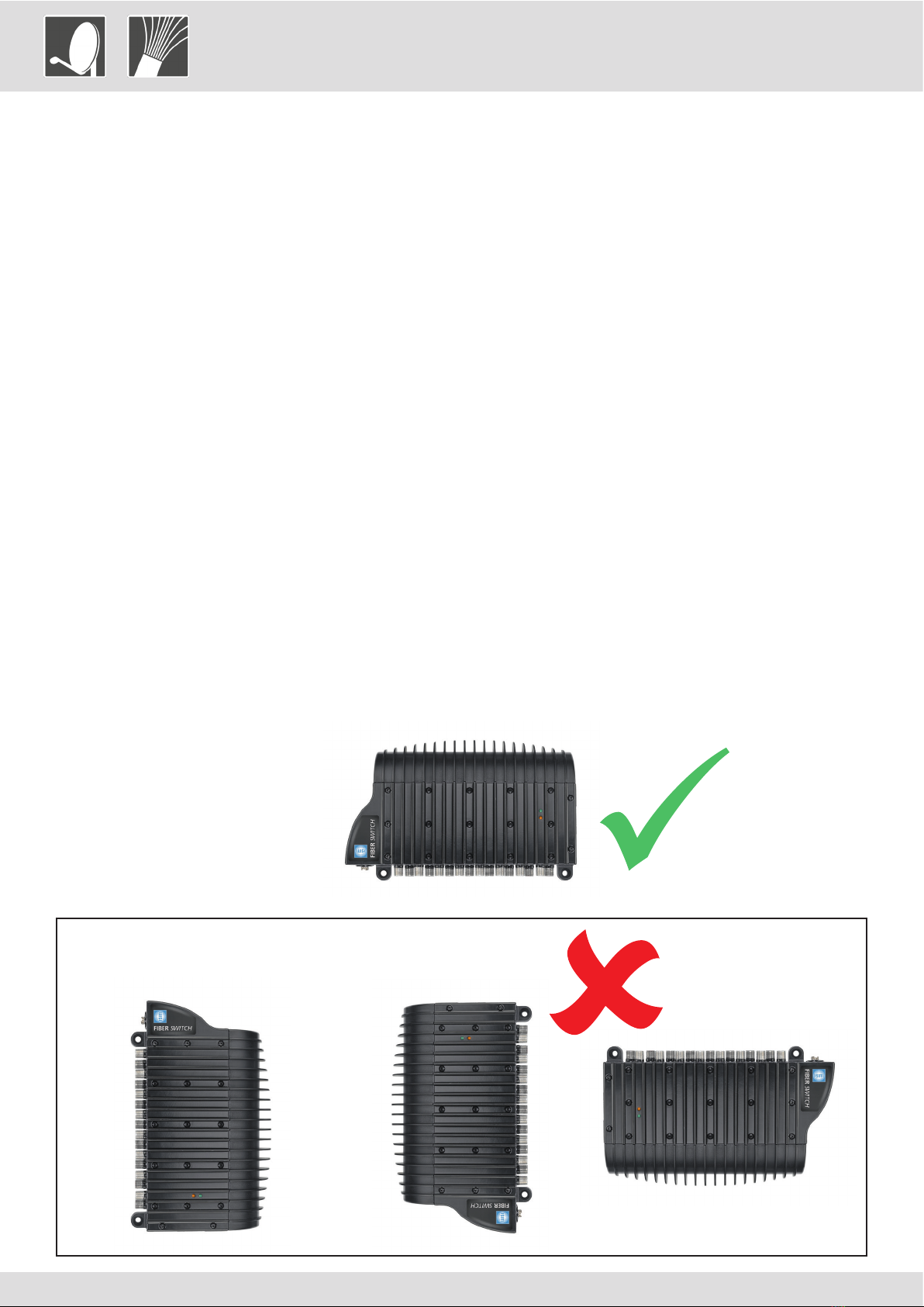
• Das Gerät ist waagrecht, mit den F-An-
schlüssen nach unten zu montieren (pic. 1)
• Das Basis-Gerät kann nun an den 4 dafür
vorgesehenen Schraubenlöchern befestigt
werden
• Das Erweiterungsgerät OL 42 xxxx wird
wie in pic. 3 gezeigt, auf das Basis-Gerät
OL 41 xxxx gesteckt. Es ist sicherzustellen
dass die Geräte vollständig verbunden sind
• Es können maximal 3 Erweiterungsgeräte
OL 42 xxxx kaskadiert werden
• Der L- Montagewinkel wird am obersten
Erweiterungsgerät montiert (pic. 4)
• Kunststoffabdeckung wieder anbringen
• Alle Koaxialkabel an die F-Anschlüsse
schrauben (Teilnehmer Ausgänge)
• Die ankommenden Glasfaserkabel aus
dem PON (passives optisches Netzwerk)
sind vor der Installation an die Geräte mit
geeignetem Reinigungsmittel (OL 57 xxxx)
zu säubern
• Netzteil an den DC-Anschluss des Basis-Ge-
rät anschließen
• Potentialausgleich über den dafür vorge-
sehene Anschluss sicherstellen
• Netzteil an 230V Versorgungspannung
anschließen
• Ensure enough clearance and ventilation
in the area the base unit and extension
unit will be fixed
• Remove the top plastic cover. Then remo-
ve the L bracket attached to the top of the
base unit (pic. 2)
• Base unit must be fixed horizontally with F
connectors facing down (pic. 1)
• Attach the base unit to the wall using the
screw holes provided
• Push the extension unit onto base unit
as shown in pic. 3 ensuring the extension
unit is fully inserted onto the base unit
• Add any additional extension unit up to
maximum of three
• Attach the L bracket to the top of the last
extension unit and fix to the wall (pic. 4)
• Replace top plastic cover
• Connect all required coaxial cables (sub-
scriber outputs)
• Clean (by using OL 57 xxxx) and connect
the fiber cables from the PON (passive op-
tical network) to the optical FC/PC connec-
tors of all units
• Connect the power supply to the DC jack
on the base unit
• Use the earthing terminal to ground the
base unit
• Power on the units
Multi- Satelliten Installation Multi satellite installation
Pic. 2
Plastic cover
Pic. 3
L bracket
Pic. 4