Wisy SIGMA User manual

Installation Instructions • Installation Instructions • Installation Instructions • Installation Instructions • Installation Instructions • Installation Instructions • Installation Instructions •
Instructions • Installation Instructions • Installation Instructions • Installation Instructions • Installation Instructions • Installation Instructions • Installation Instructions • Installation
Installation Instructions
● Operating
instructions for
the SIGMA
rainwater unit
● Please read through
these instructions
carefully before
you attempt to
install and use the
rainwater unit!
● 3- or 4-stage
self-priming
centrifugal pump
● Operates fully
automatically to
supply household
appliances on
demand
● Automatic mains
water top-up
with integral
9-litre top-up tank
● Energy efficient
technology, standby
usage less than 0.2 W
WISY
Rainwater Harvesting
SIGMA Rainwater Unit
ΣΣ
Sigma

2
30 %
5 %
Harvesting rainwater
reduces mains water
consumption by:
50 %!
WC:
30 %
Laundry:
13 %
Garden irrigation:
5 %
Cleaning:
2 %
13 %
2 %
1 Vortex fine filter (WFF)
2 Inflow calming
3 Floating
suction filter
4 Multisiphon
5 Rainwater storage tank
6 Sigma rainwater unit
7 Filter collector (FS)
8 Rainwater barrel 500 l
Stage 2
WISY inflow calming
prevents resuspension of
sediment and distributes
the fresh, oxygen-rich
water in the storage tank
Stage 3
Water is extracted with
the WISY floating suction
filter suspended
at the optimum height
Stage 4
Overflow with skim effect,
odour seal, small animal
guard and backflow pre-
vention with WISY multi-
siphon
The WISY 4-stage
rainwater cleansing
system
6
7
8
1
4
2
3
5
The WISY 4-stage rainwater cleansing principle in the single-family home
Stage 1
Filtering with WISY
vortex fine filter with
separation of dirt particles
and oxygen enrichment

3
SIGMA Rainwater Unit
Please read through these instructions
carefully before you attempt to install and
use the rainwater unit!
Original installation instructions and
usage guide for the rainwater unit
These installation instructions include the following information relating to:
● General description, applications and proper use
● Safety information and warning notices
● Delivery, scope of supply and design
● Recommended accessories
● Design and operating principle
● Installation
● Commissioning
● Maintenance, servicing
● Troubleshooting guide
● Technical data
● Guarantee conditions
● Company name and address
● Overview diagram (annex)
● Declaration of conformity (annex)
● Konformitätserklärung (Anlage)
Applications
The SIGMA rainwater unit developed by WISY is a complete rainwater harvesting
system with integral self-priming pump, control system and automatic mains wa-
ter top-up. It combines numerous individual devices to form a single package for
installation in a utility room or basement.
SIGMA pumps the rainwater out of the storage tank and feeds it under pres-
sure into the rainwater supply circuit. At the same time, SIGMA controls
the entire rainwater harvesting system, monitors the fill level of the storage
tank and automatically tops up the system with mains water when required.
SIGMA is available with an optional level indicator
SIGMA is designed to supply toilet cisterns, washing machines and garden irriga-
tion systems in single-family homes with clear, filtered rainwater.
Important preconditions for correct operation of the system:
● The suction line must be installed with a continuous rise from the rainwater
storage tank to the SIGMA unit. The wall unit must be installed above the
maximum water level in the rainwater storage tank.
● With a height difference of 3 m between the wall unit and the rainwater
storage tank base, a suction line of up to 15 metres in length may be
required (see diagram).
● The suction line must have an inside diameter of at least 1“ (2.54 cm).
● A floating fine suction filter FFSF (item SZ 9924) with non-return valve
is required in the rainwater storage tank
If the rainwater storage tank must be installed with a larger height differential or at
a greater distance from the rainwater unit due to the site topology, WISY‘s OPTIMA
/ OPTIMAPlus rainwater units can be installed. OPTIMA rainwater units operate
without a suction line and are designed to pump water over longer line distances/
height differences.
SIGMA cannot be used to supply outlets at a rate of less than 1 litre per minute
(e.g. drip irrigation systems; outlets must close completely, the rainwater circuit
must be leak-tight).
SIGMA is not suitable for pumping dirty rainwater or well water (which contains
dirt or sand particles). SIGMA cannot be used to pump water out of a dirty rain-
water storage tank. Improper use of the equipment can result in destruction of the
pump.
Contents
OPTIMA rainwater units for greater
distances and height differences
Proper use
Improper use
With floating fine
suction filter
(accessory) and
float switch
!

4
1 Mains water connection (top-up)
2 Suction line connection (from storage tank)
3 Pressurized outlet (distribution system)
4 Measuring lead for level indicator
5 SIGMA mains plug
6 Electrical connection for float switch
7 Emergency overflow drain connection (DN 70)
8 Adjusting screws for level indicator:
a) Left-hand screw: Fill level adjustment
b) Right-hand screw: Zero-point calibration
9 Level indicator
10 Operating pressure indicator
(pressure gauge)
11 Self-priming centrifugal pump
12 Automatic switch (with display
and operator panel)
13 Base frame
14 Connecting hose to pressurized outlet
16 Float switch
17 Measuring lead in storage tank, with weight
18 Screw plug for venting/filling
Accessories not included
in the scope of supply:
15 Floating fine suction filter (FFSF)
with non-return valve (accessory)
19 Isolating valves
20 Multisiphon (odour seal and
backflow prevention)
21 Water meter for mains water top-up
22 Water meter for pumped rising main
23 Flexible connecting hoses
1
8
9
10
12
2
16
3141811
13
Guide to components

5
Safety instructions
Read the operating instructions carefully before commencing assembly and in-
stallation work and store them in a safe place for later reference.
Do not lift or pull the float switch by its electric cable.
Never climb inside the storage tank when the SIGMA rainwater unit is connec-
ted to the power supply. Always unplug the SIGMA rainwater unit to disconnect
it from the power supply before carrying out any inspection, maintenance or
repair work to the SIGMA rainwater unit or inside the storage tank.
Never leave the rainwater storage tank unsupervised when it is open! No one ex-
cept specially trained personnel is allowed to climb inside the rainwater storage
tank. When working inside the tank, personnel must be supervised at all times
and must take appropriate safety precautions (e.g. wear a recovery harness).
If the residual current device or the fuse trips, the trip cause must be identified
and rectified by the manufacturer / by a contractor appointed by the manufac-
turer.
If the power cable to the SIGMA unit or the float switch is found to be damaged,
it must be replaced by the manufacturer / by a contractor appointed by the
manufacturer.
Installation work which involves particular hazards (e.g. risk to mains water sup-
ply or the electrical installation) must always be carried out by a properly trai-
ned, approved plumber or electrician who is at least qualified in the following
technical areas:
● Selection of appropriate tools and suitable electrical and installation
materials
● IP degrees of protection
● Correct methods of installing electrical and other materials
● TN-C system, TN-S system and appropriate additional measures
where necessary.
● Drinking water protection in accordance with DIN EN 1717, DIN 1989
Failure to install the equipment properly can endanger your own life and the
lives of people who use the equipment.
The system must be connected to a 230 V, single-phase AC (50 Hz) supply.
The SIGMA unit must be operated with clean water (rainwater or mains water)
which does not contain aggressive, abrasive or solid substances.
Failure to adhere to these instructions and/or unauthorized interference with
the SIGMA shall exempt WISY AG from any liability for any personal injuries,
property damage and/or damage to individual components of the SIGMA sys-
tem.
The SIGMA product is generally shipped in a cardboard box. The cardboard box
must not be dropped, crushed or handled with force, and must be inspected for
damage as soon as it is received.
The cardboard box or its unpacked contents must be stored in a safe, dry, and
frost-free location and protected against the ingress of dirt or contaminants.
Scope of supply and design
● Self-priming, multi-stage centrifugal pump with automatic switch SA 06,
pressure indication: Operating pressure max. 3.3 / 4.4 bar; delivery rate
max. 65 l/min.
● Mains water top-up function compliant with DIN EN 1717, automatically fills
the mains top-up tank (9-litre volume) integrated in the wall unit when in-
sufficient rainwater is available, float valve with dirt filter; mains top-up tank
with safety emergency overflow DN 70.
● Cover to protect the rainwater unit.
● Wall mounting kit.
● Level indicator (optional) for indicating water level in the rainwater storage
tank, with measuring lead, length 13 m, and connection kit.
● Float switch (yellow) with stainless steel clamp for attachment to tube dia-
meter 110 to 130 mm, with 15 m electric cable without plug, for connection
to the wall unit.
Additional instructions
Delivery / shipment of the unit
Wall unit for indoor installation
Storage tank equipment

6
Manual switchover to mains
water operation
Mains water operation when
rainwater level is low
Dry run protection
Accessories
Components which are not supplied as standard
● Hoses for connecting the SIGMA rainwater unit to the rainwater circuit and
the mains water top-up, two ¾“ pressure hoses with stainless steel sheath,
0.5 m in length, with 1“ union nut and ¾“ brass ball valve, with dirt trap for
mains water top-up (Item No. RW 78 00).
● 1“ full-bore brass ball valve for suction end of wall unit (Item No. ZK 04 03)
● 1” hose nozzle, brass, for suction end of wall unit (Item No. ZV 04 33)
● 1“ suction tube, flexible, max. operating pressure 20 bar (Item No. AS 20 03).
● 1“ hose clamps, made entirely of stainless steel (Item No. SS 0303).
● 1“ floating fine suction filter FFSF, with non-return valve (Item No. SZ 99 24).
● Wall or tube penetration WD 100, with 4 holes (1 x dia. 36 mm for suction line
1“, 2 x dia. 10 mm for electric cable, 1 x dia. 6 mm; Item No. WD 11 00).
Design and operating principle
The SIGMA rainwater unit draws rainwater from a storage tank and feeds it
under pressure into the rainwater supply circuit. If the water level in the storage
tank is low, the system automatically switches over to mains water operation.
A self-priming pump draws harvested rainwater out of the storage tank and
pumps it to the appliances. If a valve at one appliance (e.g. toilet flushing sys-
tem) is opened, the pressure in the rainwater supply circuit drops. The pump
starts up when the pump starting pressure (1.5 bar) at the automatic switch
is reached. When all valves at the appliances are closed again and there is no
measurable flow through the circuit, the pump control system (automatic switch)
shuts down the pump when operating pressure is reached.
Switchover to mains water top-up is fully automatic provided that the float
switch in the rainwater storage tank is securely attached to the inflow tube (in-
flow calming) at a vertical height of 30 cm above the base of the tank. If this
„minimum water level“ is reached, the float switch in the storage tank closes.
(Mains) water is now sucked out of the top-up tank integrated in the SIGMA unit.
The drop in water level in the top-up tank causes the float valve to open to allow
inflow of mains water into the top-up tank. In the rare occasion that the mains
water that is supplied to the top up tank is coming in with a very low pressure,
it can happen that the pump is drawing more water from the top up tank than
can be simultaneously replaced with mains water. The Water level in the top up
tank is falling until it reaches a low point 3 cm above bottom level. At this point a
safety control switches the pump off until the water level in the top up tank has
reached a height of minimum 13 cm again. When the Water Level is rising above
this Level the pump is automatically switched on again. When the valves at all
appliances are closed again, the pump control system shuts down the pump as
soon as operating pressure is reached (= max. delivery head).
The automatic switch provides dry run protection when there is insufficient
water in the circuit.
It is possible to manually switch the rainwater unit over to pure mains water
operation while maintenance work is in progress or when water of a particularly
quality is required. Manual switchover is possible irrespective of the fill level in
the rainwater storage tank. Mains water operation can be selected by means of
an electric switch on the side of the automatic switch. If the switch is turned on,
the self-priming pump automatically extracts water from the mains water top-up
tank when an appliance valve is opened.
Supply with rainwater

7
ZETA 02 Programming
Note:
The “Reset” button on the Zeta 02 serves two functions, if pressed for less than 1 sec. it will go into reset mode, pump starts
running. If pressed for longer it will go into one of the programming modes below
Programming Run-on-time.
Mode 1 – Fast Flash
To Enter – Press and hold reset button (3 secs). Then briefly press reset button to toggle between settings.
To save the setting press and hold the reset button until the power light stops flashing (approx. 3 secs.)
FAST FLASHING
●
OFF
●
OFF
FAST FLASHING
●
ON
●
OFF
FAST FLASHING
●
OFF
●
ON
FAST FLASHING
●
ON
●
ON
10 sec Run-on-time
5 sec Run-on-time (Default and
recommended setting for normal use)
3 sec Run-on-time
1 sec Run-on-time
Programming excess pump run and starts functions
Mode 2 – Slow Flash
To Enter – Press and hold reset button (6 secs). Then briefly press reset button to toggle between settings.
D = Excess pump run function
D on – Pump stops after 10 minutes continuous run. (May need to leave this off for some irrigation applications).
T = Excess pump starts function.
T on – Pump stops after 25 starts per hour. (Where multiple starts are occurring, we would recommend installing a
pressure vessel).
Save the setting by pressing and holding the reset button until the power light stops flashing (approx. 3 secs.)
IF either of these functions has switched the pump off, THEN the fault light (only) will show. IF the fault light AND the power light
show then this indicates that a “Dry Run” type fault has occurred. (i.e. No flow arrived at the zeta 02 when the pump power was on)
SLOW FLASHING
●
OFF
●
OFF
SLOW FLASHING
●
ON
●
OFF
SLOW FLASHING
●
OFF
●
ON
SLOW FLASHING
●
ON
●
ON
D off (Default)
D off
D on
D on
T off (Default)
T on
T off
T on

8
Connect the emergency overflow DN 70
!
!
Rinse piping and hoses
Note the length, height difference and
continuous rise of the suction line from the
storage tank base up to the Sigma unit!
SIGMA with level indicator
Installation requirements
The SIGMA system must be installed by specially trained installation personnel,
i.e. by properly qualified, approved installation specialists and electricians. This
is a basic requirement for maintaining the validity of the manufacturer‘s guaran-
tee.
The SIGMA unit must be installed above the backflow level in a frost-free room
which has a floor drain. Special measures must be implemented if the unit is
installed and operated below the backflow level. Please contact WISY AG‘s
technical support team for advice about installation below backflow level.
The suction tube must be installed with a continuous rise up to the SIGMA wall
unit. The tube must have an inside diameter of at least 1“ (2.54 cm).
With a height difference of 3 m between the tank base and the SIGMA unit, a
suction line of up to 15 metres in length might be required (maximum values).
For a SIGMA unit with level indicator, the measuring lead (for the level indicator)
must be installed with a continuous rise up to the wall unit.
The emergency overflow (DN 70) of the mains top-up tank must be permanently
and securely connected to a drain (minimum DN 70). The room in which the
SIGMA unit is installed must have a floor drain.
The water column between the bottom edge of the wall unit and the highest
operating point (valve at appliance) must not exceed 15.0 m.
The wall unit and the supply lines must not be installed in locations which are
exposed to substantial heat sources, as temperature rises in these components
can cause the system pressure to increase and result in component damage.
Piping or hoses must be cleaned or flushed through before use to remove any
deposits of dirt/dust caused by building work. Protective plugs must be remo-
ved before pipes or hoses are connected.
Attention to backflow level and floor
drain in the installation area

9
Connection to the indoor pipework
Installation of components in the
rainwater storage tank
Installation
Line up the wall mounting kit horizontally and attach it to the wall. The wall-
mounting bracket can be used as a drilling template. The distance between the
holes is 28 cm. The wall unit can then be inserted in the groove of the bracket.
The connection between the wall unit and the rainwater supply circuit / mains
water pipe must be high pressure resistant, flat-sealing and acoustically isola-
ted. The ball valve with dirt trap (accessory hose connection set RW 78 00) must
be used to connect the rainwater unit to the mains water pipe.
Clamp the float switch to the inflow calming tube in the rainwater storage tank at
a vertical distance of between 30 and 35 cm from the tank base.
Attach the floating fine suction filter with the stainless steel hose clamp to the
suction hose in the storage tank.
Route the electric cable for the float switch and the suction hose (and possibly
the measuring lead for the level indicator) through a service duct into the utility
room of the building.
Fill the suction hose with water, then attach it with hose nozzle and isolating
valve to the suction end of the SIGMA wall unit with a hose clamp.
Do not install any flow restrictions (water meters, filters, drain cocks, etc.) in the
SIGMA suction line.
Mains connection protected by RCD
The mains power connection (AC, single-phase, 230 V, 50 Hz) of the
SIGMA rainwater unit must be equipped with a residual current device (0.03 A)
and protected by a 16 A fuse.
Wire up the connecting cable of the float switch to the plug supplied. See photo-
graph on left for correct termination of wires. Insert the plug into the grey socket
outlet which is located on the underside of the wall unit.
All electrical work must be carried out in accordance with the safety instructions
given on page 5.
Install the wall unit inside the building
top
rear panel
of casing
Note height of
top edge of unit
Electrical connection of indoor wall unit
blue
yellow/green
black, grey
or brown
Insert
Commissioning the SIGMA
1. Completely fill the pump unit and the suction hose with water. The
suction hose can be filled directly, but the pump must be filled with water by
opening the screw plug.
2. Open the isolating valve in the mains top-up pipe. The top-up tank
fills up with mains water.
3. Open the valves at the appliances.
4. Connect the SIGMA to the electricity supply.
5. As soon as system has been bled, close the valves at the appliances!
When the maximum operating pressure is reached (maximum delivery
head, see technical data), the SIGMA is ready to operate.
Power plug for float switch

10
Applications
Mounting location
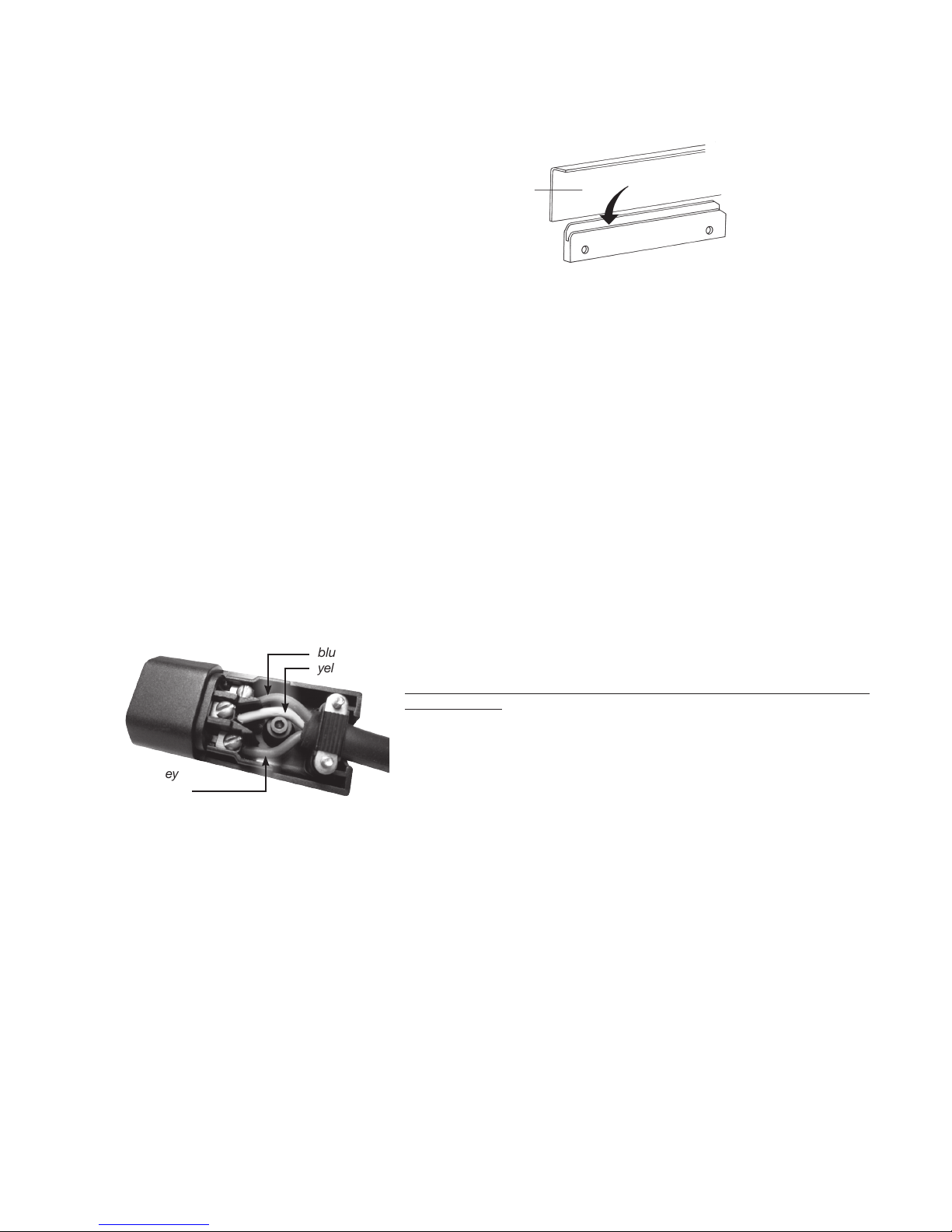
Installation instructions for measuring lead
Connect yellow measuring lead to
connector on the underside
of the SIGMA wall unit
Universal, pneumatic fill level meter with capsule-type element and integrated
electric pump for measuring fill levels in tanks. Steplessly adjustable to tank
heights of between 100 cm and 250 cm (adjustable by the hexagon socket
head screw); zero-point calibration of needle (adjustable by the Phillips-head
screw). Measuring accuracy of the measurement mechanism is +/- 3% of full
scale value. The electrically operated pump closes the measuring system at the
top dead point. The needle remains stationary briefly and then drops very slowly
down. The water stop air cushion produced in this way protects the capsule
element.
Universal connection for the measuring lead (PE tube) with 8 mm outer diameter.
Fill level is indicated in % irrespective of the tank shape.
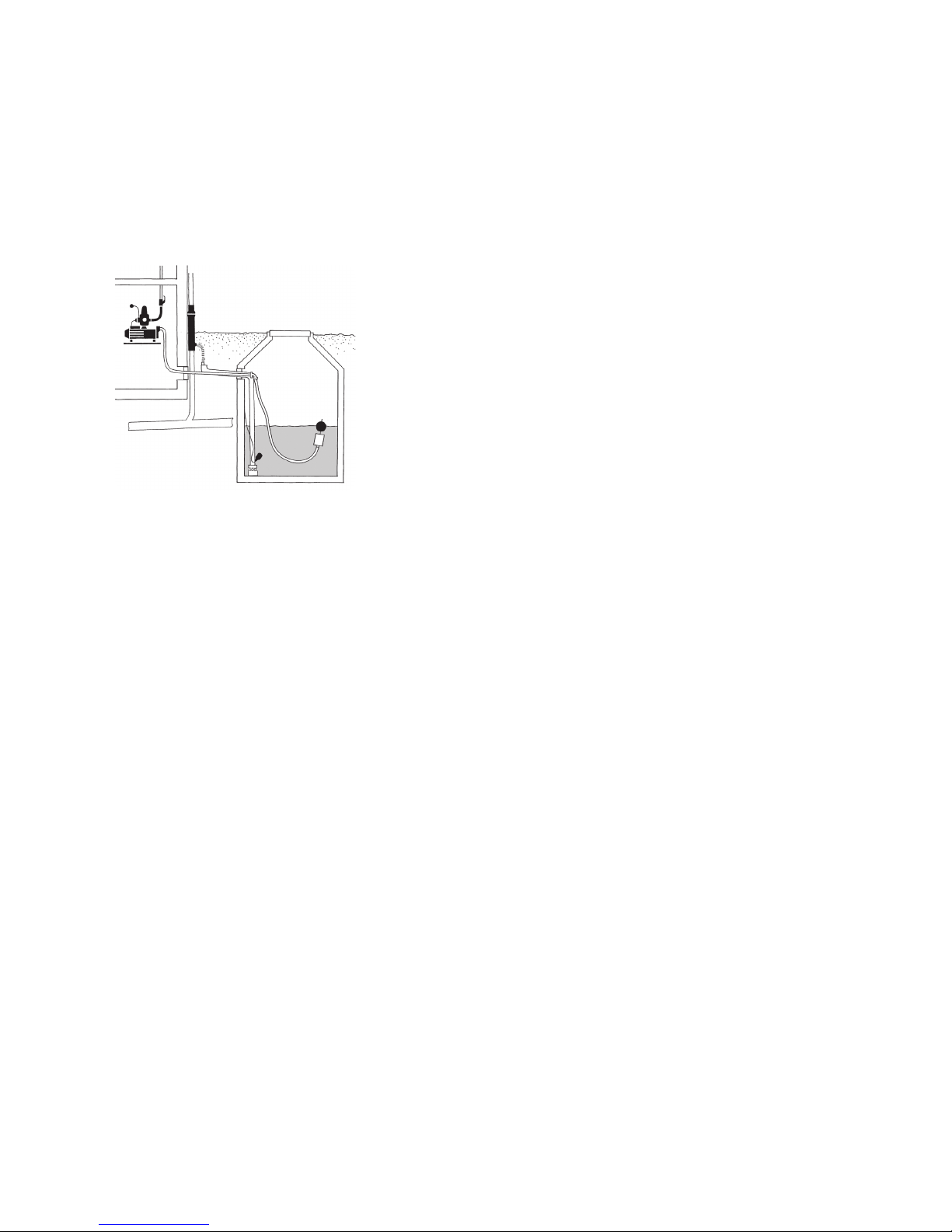
Standard application is for water level height in the storage tank of between 100
and 250 cm and distances of around 10 m between the SIGMA wall unit with fill
level meter and the rainwater storage tank (measuring lead length 13 m). Positi-
on of normal use is vertical. Ambient temperature: 0°C to +40°C.
Protected against direct exposure to weather and solar radiation.
Install the measuring lead (yellow PE tube) with a continuous fall towards the
tank. Do not bend the lead (to prevent water pockets!).
Install the rubber-insulated measuring lead with brass weight in the storage tank
in such a way that it is suspended vertically and ends at approximately 5 cm
above the tank base, then connect both tubes with the brass coupling.
To connect the measuring lead to the measuring instrument connector (on the
underside of the SIGMA wall unit), assemble the individual components in the
order illustrated in Figure 1 at the end of the yellow PE tube, insert the tube as
far as it will go into the connector and gently tighten the hexagon bolt.
Device setting instructions
Remove the cover from the SIGMA unit.
Precisely adjust the measuring range (corresponds exactly to the maximum
water fill level in the storage tank up to the overflow) on the adjustment scale
using the hexagon socket head screw (failure to do this properly will result in
measuring errors!).
Use the zero-point calibration screw to position the needle at „0“. Turn the
screw by maximum one revolution to the left or right until the needle is pointing
to „0“. If the tank has already been filled and the pump started, the measuring
system will need to be „depressurized“ before the zero point can be calibrated.
This can be done by detaching the measuring lead from the connector at the
wall unit.
Description of level indicator unit
A measurement of the fill level of the storage tank is triggered only if the SIG-
MA pump starts up. During the pneumatic measuring process, the hydrostatic
pressure is measured. This varies depending on the water level in the tank. The
pressure is generally measured at a height of 5 cm above the tank base and is
converted to a fill level percentage on the clock dial.
The pump of the measuring instrument is used to build up pneumatic pressure in
the measuring system until this pressure is equal to the water pressure applied
to the base of the tank. The needle is now in its maximum position. The pressure
generated by the pump has displaced the water column from the measuring
lead suspended in the water (black rubber hose). Bubbles of air escape from
the end of the hose on the tank base and the needle remains temporarily in the
measurement position. Once the SIGMA has returned to its „normal position“,
the needle gradually drops back to the „0“ position.
Description of function
Level indicator
Scope of supply of basic equipment
SIGMA with level indicator
This description applies to installation of a pneumatic level indicator in the SIG-
MA rainwater unit. The function descriptions of the measuring instrument, the
installation instructions for the measuring lead and the device setting instruc-
tions are all important.
PE measuring lead (yellow), a brass hose coupling, 3 m rubber-insulated tube
(black) with brass weight and a connection kit for the measuring lead (small
parts supplied in small plastic bag).
Replacement / extension kits, each containing 10 m of PE measuring lead with
brass hose coupling, can be ordered (WISY Item No. FA 9915).
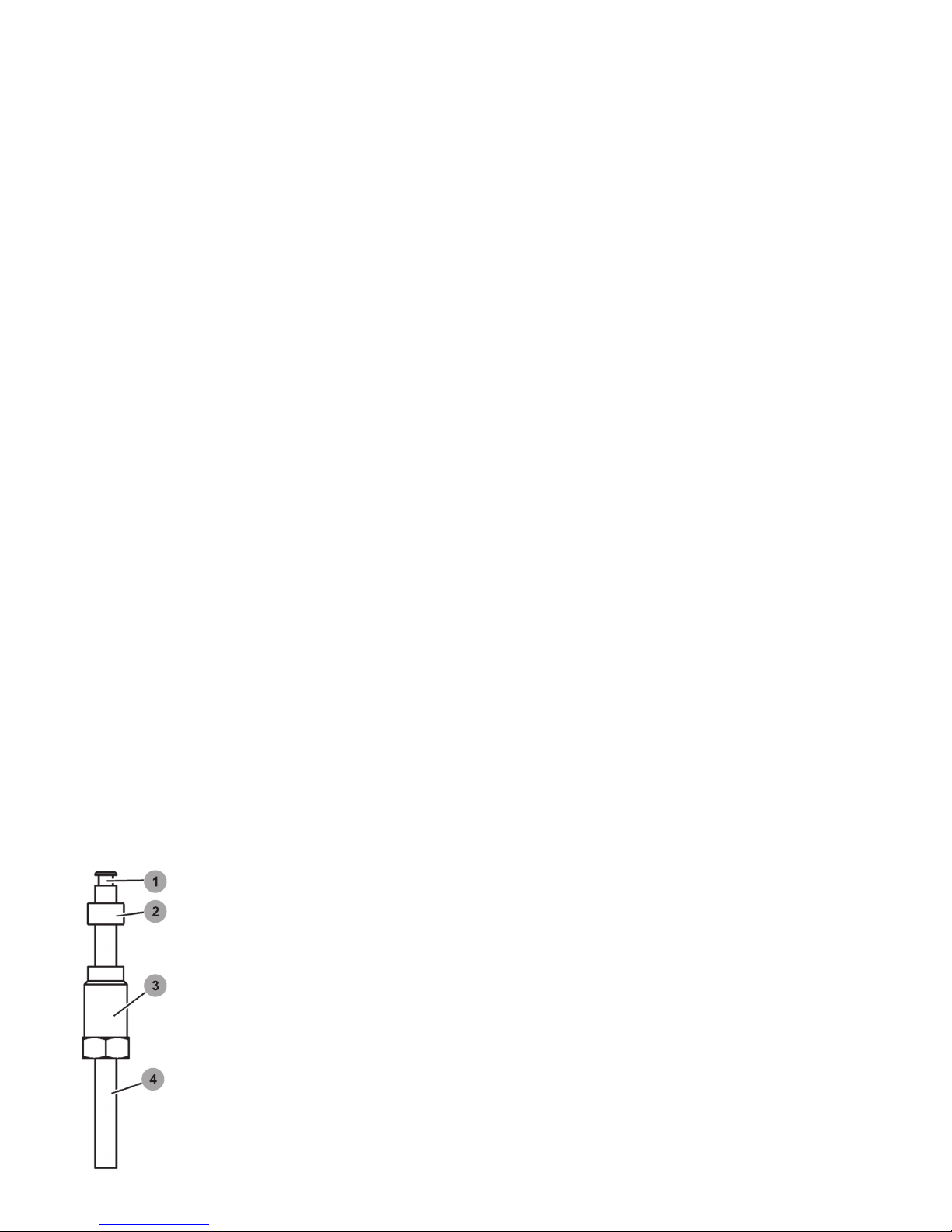
A connection kit
includes:
1. Brass tubular rivet
(as „support“)
2. Rubber seal
3. Hexagon bolt (black
plastic) with hole to insert
yellow measuring lead; is
screwed into connector
on wall unit
4. Yellow measuring lead

11
Indication errors and causes
● Needle does not move when measurement is taken / drops very quickly
back to 0: Leak in connections or connecting lead, „depressurize“ the
measuring system (see device setting instructions)! Hold a finger over the
measuring instrument connector on the wall unit and start SIGMA by pres-
sing the RESET button on the automatic switch (in wall unit)! If the needle
moves to its maximum position, the measuring instrument and the connec-
tions inside the wall unit up to the measuring instrument connector are OK.
The connections and connecting lead must be inspected for leaks!
● Needle moves to beyond 100% position: The measuring lead is blocked or
bent, or the measuring range is set incorrectly.
● Indication error: The device is incorrectly set. Check the fill level in the tank,
correct on the adjustment scale!
Maintenance and servicing
Inspections/tests at 6-monthly intervals:
● Inspect the SIGMA system and the water circuit connections for leaks
● Check the system pressure indication
● Test the pump start and stop points at the automatic switch
● Test mains water operation, e.g. by setting the switch on the side of the au-
tomatic switch to „mains water mode“ and closing the isolating valve at the
suction end
Inspections/tests at 12-monthly intervals:
● Inspect the dirt trap at the isolating valve of the mains water connection,
clean the trap if required (call in a specialist if necessary)
● Inspect the floating fine suction filter in the rainwater storage tank and clean
if necessary from ground surface level using a water jet or a long-handled
brush (call in a specialist if necessary)
Replacement:
● The solenoid valve at the mains water outlet must be replaced by a
specialist after the system has been in operation for 10 to 15 years.
Repairs
All repair work must be carried out by the manufacturer or by contractors who
have been explicitly approved by the manufacturer. Repairs, modifications to
components or modifications to factory-assembled SIGMA components carried
out by unauthorized persons shall invalidate the guarantee!
The SIGMA rainwater unit must be
disconnected from the mains power
supply before any maintenance work is
carried out on the open storage tank.
Compliance with the safety instructions
(see heading „Safety instructions“ in this
document) is absolutely essential!
!
Environmental guidance
The SIGMA rainwater unit is shipped in recyclable cardboard packaging.
Please recycle it as waste paper! Please take the Styropor packaging to your
local recycling centre.
Waste electrical and electronic equipment often contains valuable materials
which can be reused / recycled. However, they also contain harmful substances
which are essential to the proper, safe operation of the equipment.
These substances pose a risk to human health and to the environment if the
products are disposed of as general (non-recyclable) household waste or are
incorrectly handled. For this reason, you must never dispose of an old unit as
general (non-recyclable) household waste.
Use the recycling centres / facilities provided in your area to return defective
electrical or electronic equipment so that it can be recycled!
Disposal / recycling of
transport packaging
Disposal / recycling of old units

12
Troubleshooting guide
Type of fault Cause Remedy
SIGMA is not supplying water
to the appliance(s)
a) Rainwater storage tank is empty, isolating
valve to mains water pipe is closed The dry
run protection function of SA 06 is active
b) The pump is sucking in air through the
suction line
c) Automatic switch SA 06 is not starting the
pump
d) The pump is blocked
e) The power supply is interrupted
a) Open the isolating valve, bleed the SIGMA
unit and the entire rainwater circuit, start
the pump by pressing the RESET button on
the automatic switch (SA 06)
b) Check that the suction line and the floating
fine suction filter (FFSF) are correctly posi-
tioned and leak-tight; correct if necessary;
bleed the system
c) Press the RESET button! Call customer
service
d) Call customer service
e) Check the electrical connection, contact
customer service if necessary
The automatic switch SA 06 is switching the
pump on and off continuously
a) Leak in the system, valves at appliances
are not fully closed
b) Automatic switch is soiled internally/ is
defective
a) Check the valves at appliances and the
rainwater supply circuit for leaks
b) Call customer service
Frequent switching of the pump causes
pump damage – disconnect SIGMA from
the power supply
Pump is running continuously a) Water loss of more than 0.7 l/min from
the system
b) Electronic circuitry (PCB) of the SA 06
is defective / SA 06 switch is defective
a) Check the valves at appliances and the
rainwater supply circuit for leaks
b) Replace the PCB or the SA 06 switch
(customer service)
Pump is not producing enough pressure a) The floating fine suction filter / filter casing
of the FFSF is dirty
b) The pump is sucking in air
through the floating fine suction
filter (FFSF)
c) The pump is defective
a) Clean the floating fine suction filter (FFSF)
with a water jet or a fine brush
b) Check the position of the floating fine
suction filter in the storage tank and
correct if necessary
c) Call customer service
The residual current device has tripped a) Water or moisture on electrical
components
b) SA 06 is not operating
c) The pump or pump cable is defective
d) The float switch or float switch cable is
defective
a) Check the electric cable at the SA 06, the
cable between the pump and the SA 06
and the cable with plug to the float switch,
call customer service if necessary
b) Check the power supply and, if necessary,
the PCB / SA 06, customer service!
c) Call customer service
d) Call customer service
Continual top-up with mains water even when
the water level in the rainwater storage tank
is sufficient
a) Movement of the float switch in the storage
tank is hindered, i.e. it cannot float
b) The solenoid valve at the mains water
outlet is not closing
a) Inspect the float switch, remove the
blockage (customer service)
b) Perform a function test on the solenoid
valve, replace if necessary, call customer
service
Switchover from rainwater operation to
mains water operation is not working and
the automatic switch is indicating a fault
a) The float valve in the mains water top-up
tank is blocked or is not opening
b) The float switch in the storage tank is
blocked
c) The float switch is not transmitting any
signals to the solenoid valve
a) Perform a function test on the float valve,
clean it if necessary, call customer service
b) Perform a function test on the float switch
(customer service)
c) Check the float switch, replace if
necessary (customer service)
Mains water is continuously running out
through the emergency overflow of the mains
top-up tank (audible!)
The float valve in the mains top-up tank
is not closing
Check the valve; call customer service
Inadequate top-up with mains water,
the dry run protection function is active
The float valve for mains water top-up is
blocked or the dirt filter at the valve inlet is
clogged
Clean the float valve or the dirt filter, replace if
necessary, customer service
The pressure gauge (pressure indicator) is
showing a raised pressure
An external heat source (e.g. radiator) is cau-
sing a pressure rise in the SIGMA rainwater
supply circuit
a) Remove the heat source (if possible)
b) Contact customer service of your
installation company (it might be necessary
to install a pressure relief valve)
SIGMA units with level indicator:
The indicated fill level does not match the
actual fill level in the storage tank
See also section headed „SIGMA with level
indicator“
a) Basic setting error
b) Measuring lead is defective / not leak-tight
c) Level indicator is defective
a) Refer to operating instructions under
heading „SIGMA with level indicator“,
„Device setting instructions“
b) Contact customer service of your installati-
on company if necessary
c) Contact customer service of your installati-
on company
TW = Trinkwasser

13
Technical data
SIGMA 3 SIGMA 4
Power consumption
Motor power P1 (W)
Solenoid valve (W)
Standby consumption
600
8
< 0,2 W
800
8
< 0,2 W
Mains connection
1-phase AC
230 V, 50 Hz 230 V, 50 Hz
Rated current (A) 2,7 3,5
Degree of protection
Aspri suction pump
ZETA 02
Solenoid valve
Float switch
IP 55
IP 44
IP 65
IP 68
IP 55
IP 44
IP 65
IP 68
SIGMA water connections:
Inlet connection from
rainwater storage tank
Mains water connection
Outlet connection to appliances
(OT=outside thread, IT= inside thread)
1“ AG
¾“ AG
1“ AG
1“ AG
¾“ AG
1“ AG
Sound pressure level dB (A)
in decibels in
rainwater operation
mains water operation
45
63
47
63
Delivery head Hmax (m)
Flow rate Qmax (l/min)
33
65
44
65
Operating data
Max. operating temperature (°C)
Max. water temperature (°C)
Max. startup frequency per hour
Pumped fluids
40
35
20
0.28 mm / 0.44 mm
finely filtered rainwa-
ter, mains water (clear
water containing no
aggressive or abrasive
substances)
40
35
20
0.28 mm / 0.44 mm
finely filtered rainwa-
ter, mains water (clear
water containing no
aggressive or abrasive
substances)
Max. operating pressure (bar) 10 10
Electric connecting cables
Float switch
ZETA 02 (SIGMA mains cable)
15 m, bare cable end
(3 x 1 mm2)
1.4 m, with plug
(3 x 1 mm2)
15 m, bare cable end
(3 x 1 mm2)
1.4 m, with plug
(3 x 1 mm2)
Materials
Suction pump of SIGMA 3 and 4 systems
●Suction and discharge casings made of dezincification resistant brass
●Pump casing and impellers made of stainless steel AISI 304
●Shaft made of stainless steel AISI 420
●Carbon / ceramic mechanical seal
●Diaphragms made of glass-fibre reinforced Noryl®
●Motor enclosure made of light metal L-2521
Automatic switch
●Polyamide, polypropylene (casing)
Mains water top-up tank
●Polystyrene (tank)
●Float valve made of KTW-approved plastic
Screw connections, pump connections
●Brass, stainless steel
Connecting hoses
●Natural rubber with stainless steel braiding
SIGMA rainwater unit casing
●Stainless steel (base frame)
●Polystyrene (cover)
Float switch
●Polypropylene (casing)
●Polyamide, PG 11 (cap nut)
●Neoprene cable

14
Konformitätserklärung • Konformitätserklärung • Konformitätserklärung • Konformitätserklärung • Konformitätserklärung • Konformitätserklärung • Konformitätserklärung •
erklärung • Konformitätserklärung • Konformitätserklärung • Konformitätserklärung • Konformitätserklärung • Konformitätserklärung • Konformitätserklärung •
Declaration of Conformity
WISY
Rainwater Harvesting
Product name
Applicable EU Directives
Angewandte harmonisierte
Normen
Other applied national
standards and specifications
Manufacturer
Authorised person with
responsibility for technical
documentation
Kefenrod, 14. Februar 2013
As defined by the EU Machinery Directive 2006/42/EC,
Annex II, Part 1, Section A
We hereby declare that the machinery specified below conforms
to all requirements of the EU Machinery Directive 2006/42/EC.
Multimat rainwater units, type 205, type 407
Optima 4, Optima 5, Optima Plus rainwater units
Maxima rainwater units, type 205, type 407
Sigma 3, Sigma 4 rainwater units
Delta rainwater unit
Machinery Directive 2006/42/EC of 17.05.2006
Electromagnetic Compatibility Directive 2004/108/EC of 15.12.2004.
EN ISO 13849-1:2008 Safety of machinery –Safety-related parts of
control systems - Part 1: General principles for design (ISO 13849-1:2006)
EN 809:1998+A1:2009 Pumps and pump units for liquids.
Common safety requirements.
EN ISO 12100:2010 Safety of machinery: General principles for
design – Risk assessment and risk reduction (ISO 12100:2010)
EN 60204-1:2006 Safety of machinery – Electrical equipment of
machines – Part 1: General requirements
EN 60529 (VDE 0470-1) Degrees of protection provided by enclosures
DIN 1989 Rainwater harvesting systems, Parts 1+4
DIN EN 1717 and DIN 1988-100 Protection against pollution of
potable water installations
WISY AG
Oberdorfstraße 26
D-63699 Kefenrod
WISY AG
Oberdorfstraße 26
D-63699 Kefenrod
Arnold Denk
Managing Board
of WISY AG
Jan Maurer
Managing Board
of WISY AG

15
Guarantee
This guarantee is valid for a period of 24 months and becomes effective on the
date of purchase by the system operator. Replacement of the product under
guarantee will not extend the original period of the guarantee.
WISY shall meet its guarantee obligations for the rainwater unit if it can be
demonstrated that the following conditions are fulfilled:
1. The product has been purchased from a specialist WISY retailer.
2. The product has been commissioned by the WISY customer service or by a
specialist company.
Claims can be made under the guarantee only if WISY receives notification in
writing of any defect within 14 days of discovery of the defect.
During the guarantee period, WISY shall repair or replace free of charge any
defective part. Additional claims for damages shall be excluded to the extent
permitted by law.
Faults or defects which arise as a result of the following factors are not
covered by the guarantee:
● Faulty assembly or installation, e.g. failure to comply with the valid
VDE regulations or the operating instructions.
● Failure to provide a floor drain in the utility room/installation area.
● Inappropriate use or exposure to excessive mechanical strain.
● The connection of equipment other than the pump / float switch supplied
with the SIGMA system to the socket provided on the SA 06 automatic
switch / socket outlet of the float switch.
● External influences, e.g. shipping damage, damage caused by shock im-
pacts, damage caused by exposure to weather, damage caused by soiling,
damage caused by other natural phenomena.
● Repairs or modifications undertaken by unauthorized third parties.
Period and commencement
of the guarantee
Terms and conditions
of the guarantee
Content and scope of the guarantee
Limitation of the guarantee

Installation Instructions • Installation Instructions • Installation Instructions • Installation Instructions • Installation Instructions • Installation Instructions • Installation Instructions •
Instructions • Installation Instructions • Installation Instructions • Installation Instructions • Installation Instructions • Installation Instructions • Installation Instructions • Installation
OT Hitzkirchen
Oberdorfstraße 26
D-63699 Kefenrod
Telephone (++49) 60 54 - 91 21-0
Telefax (++49) 60 54 - 91 21-29
E-Mail info@wisy.de
Internet www.wisy.de
Sales
Telephone (++49) 60 54 - 91 21-33
Telefax (++49) 60 54 - 91 21-29
Ordering/Billing
Telephone (++49) 60 54 - 91 21-25
Telefax (++49) 60 54 - 91 21-28
Technical Support
Telephone (++49) 60 54 - 91 21-78
(++49) 60 54 - 91 21-77
For up-to-date information
about rainwater harvesting
and all our products, please
visit: www.wisy.de
AHA046-E-V06-20160906 / We reserve the right to make technical changes.
Device no.
The registered manufacturer device number of your product is as follows:
Other manuals for SIGMA
1
Table of contents