WisyCom MFL User manual

MFLUserManual
RFoverFiberSystem
Upto4ch’sinasinglemodefiber
Diversityreceptionantennaremoting
IFBtransmissionsremoting
Integratedtunablefilters
Optical&RFpowermeter
Ethernetconn.forremotecontrol
SN:________________
rev.02(ref.FW1.1)
Date:23April,2014

MFLUserManual
rev.02

rev.02MFLUserManual
B
RIEFDESCRIPTION
MFLprovideswidebandopticallinkforupto4RFchannelscombinedinonesinglemodefiberthankstoCWDMtechnology.Itisdesignedtoallow
foraflexibleandmodularconfigurationthankstoamainboardthatcanbefittedwithupto4plug‐inboardsthatcanbechosenanycombination
oftwotypes:
•TX:Laseropticaltransmitter,(CDWM)plug‐inboard
•RX:Optical‐receiverplug‐inboard
Exampleofsomepossibleconfigurations:
‐MFL‐TTTTisa4lasertransmittersonchannel51/53/55/57(λ=1510/1530/1550/1570nm).
‐MFL‐RRRRisa4opticalreceiveronchannel51/53/55/57
‐MFL‐RRTThas2receiveronch.51/53and2transmittersch.55/57(itworkswithMFL‐TTRR)
‐MFL‐TTRRhas2transmitteronch51/53and2receiveronch.55/57(itworkswithMFL‐RRTT)
Mainfeatures:
CWDMLASERstofitmanyRFchannelsoverasinglefiber
LOWNOISEDESIGNtoallowgreatcoveragewhenusedtoremotereceivingantennas
HIGHINTERFERENCEIMMUNITYthankstohighIIP3designandacontrol/compensationofgain
EASYTOUSEthankstointegratedRF/opticalpowermeterandopticalpowercompensation
DIGITALLYTUNABLEFILTERS25MHzbandwidth,centerfrequencytunableover404‐788MHz(optional)
INTEGRATEDFAILSAFEREDUNDANCY:ItcanrouteRFthroughanexternalfilterortoadditionalreceiver(redundancy)toeasilyimplementa
failsafeconfigurationthatcanswitchonaredundantreceiverortransmitterifanyfaultisdetected
IFBMODE:ItcanrouteanIFBhighpowersignaltotransmitlocallyandsendIFBcarrieroverfibertoslaveunits.Whenitisworkingalongwitha
MTK952MSinslaveconfiguration,thefiberlossisautomaticallyrecoveredandtheunitincreasesthegainsothatthetransmitterpowerequals
thetargetlevel(measuredwithanpower/SWRmeterintegratedintotheMTK952MS)
REMOTEMONITOR/CONTROL:thankstoadatalinkonEthernet10/100BaseTx
REDUNDANTAC/DCPOWERSUPPLY:
‐AC:90V‐264V~,47‐63Hz,2Afused,max60Watts
‐DC:10‐28Vdc(max5A),[XLR‐4M]VDC‐pin4/GND‐pin1/NC‐pin2/NC‐pin3
NOTE:ifbothAC/DCpoweraresupplied,thedeviceusesonlyACpowersupply
RFINPUT/OUTPUT:
‐4Nconnectorfemale50Ωwithswitchable12Vboostingpower(onlyontransmittermodules)
‐2BNC‐F50Ωeachopticaltransmittermodule,failsafeoptionorexternalRFfilter
‐1BNC‐F50Ωeachopticalreceivermodule,failsafeoption
OPTICALINPUT/OUTPUT:5connectorsSC‐APCtype
DATALINK:EthernetonRJ4510/100BaseTX

MFLUserManual
rev.02
S
AFETYINSTRUCTION
Readthissafetyinstructionandthemanualfirst
Followallinstructionsandinformation.
Donotlosethismanual.
Donotusethisapparatusundertherainornearthewater.
Donotinstalltheapparatusnearheatersorinhotenvironments,donotuseoutsidetheoperatingtemperaturerange.
Mounttheapparatusasindicatedintheinstruction,donotblocksidegridsforairventilation
ATTENTION:supplytheapparatuswithacorrectmainsvoltageandwiththegroundconnection.Checkthepowercordintegrity.
Thepowercordmustbeprotectedfromdamage
Donotinstalltheapparatusnearheatersorinhotenvironments,donotuseoutsidetheoperatingtemperaturerange.
Donotopentheapparatus,onlyqualifiedservicetechnicianareenabledtooperateonit.Theapparatusneedsservicingwhenitisnot
properlyworkingorisdamagedbyliquids,moistureorotherobjectsarefalleninsidetheapparatus.
Useonlyaccessoriesorreplacementpartsauthorizedorspecifiedbythemanufacturer.
Cleantheapparatusonlywithdrycloths,donotuseliquids.
TheON/OFFisadoublepolecircuitbreaker,buttoensurethecompletedisconnectionoftheapparatus,disconnectthepowercord.
Reporttheserialnumberandthepurchasingdateinfrontofthemanual.Itisneededtohaveproperreplacementpartsoraccessoriesfrom
themanufacturer.
Whenreplacementpartsareneeded,useonlyreplacementpartsauthorizedfromthemanufacturer.Substitutionwithnotauthorizedparts
couldresultinelectricshock,hazardsorfire.
Keepattentiononallthelabelswithwarningsorhazardsontheapparatus.
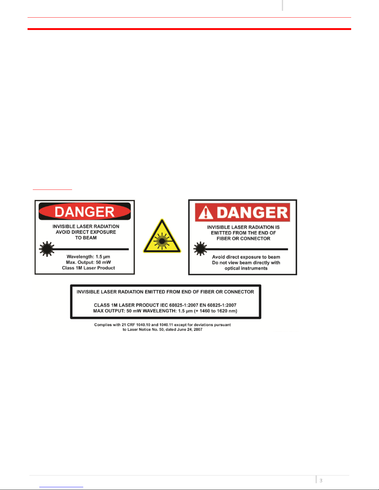
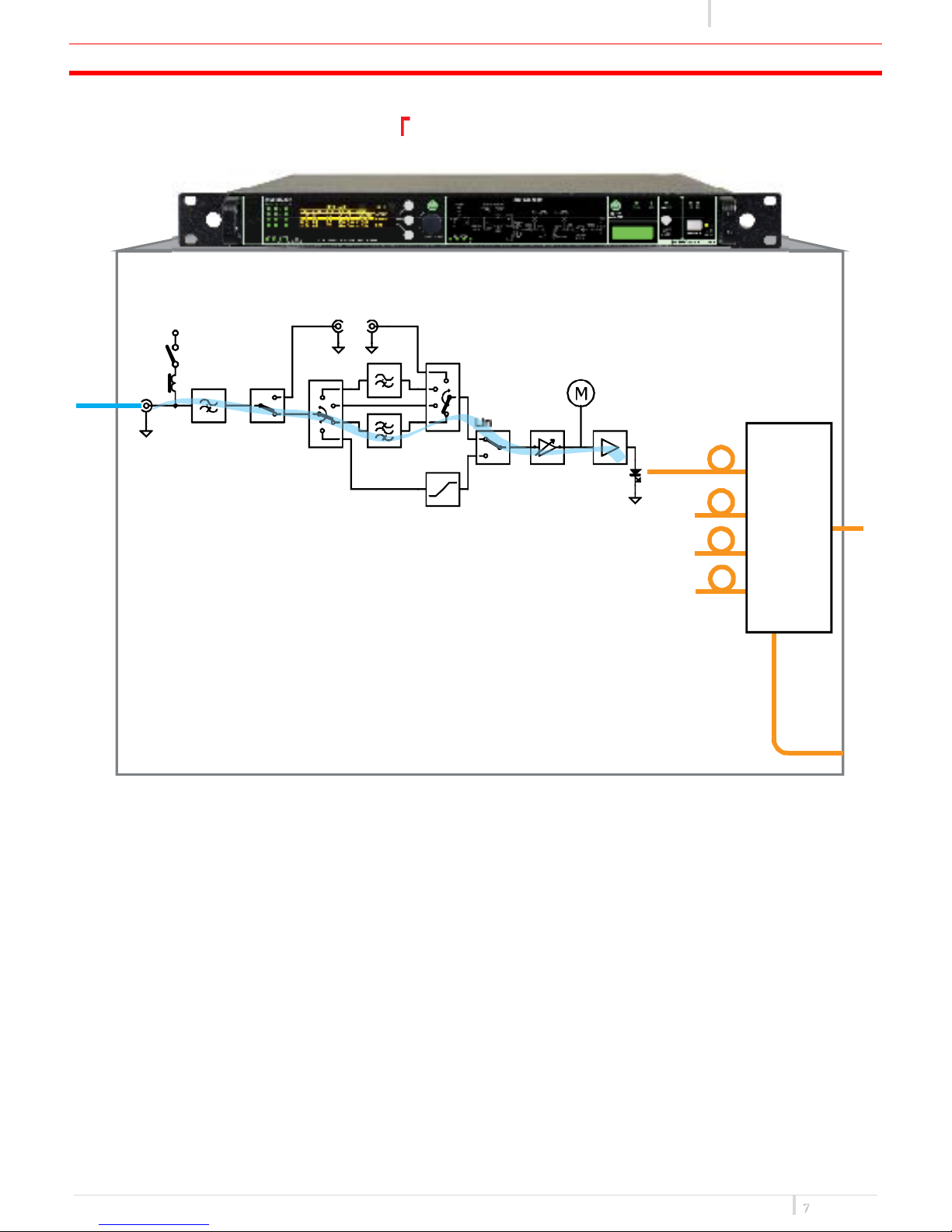
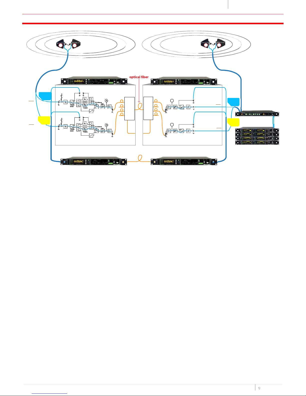
OpticalSafety!!!
WisycomMFLcontainslaserdiodesourcesoperatingat1460to1620nm.
ThesedevicesareratedatunderIEC60825‐1:2007asCLASS1MLASERPRODUCT
Neverlookintotheendofanopticalfibredirectlyorbyreflectioneitherwiththenakedeyeorthroughanopticalinstrument.Neverleave
equipmentwithradiatingbarefibresaccessible–alwayscaptheconnectors.
Donotremoveequipmentcoverswhenoperating.
Adjustment,maintenanceandrepairoftheequipmentshouldonlybecarriedoutbysuitablyqualifiedpersonnel.
Thisproductissuppliedwithangle‐polishedconnectorsandthesemustnotbeconfusedwithstandardflat,sphericalor"super"polished
connectors.Theseconnectortypesarenotinterchangeableandmatingonewiththeotherwilldamageboththecableandtheequipment.
Thespecificationoftheopticalconnectoriscriticaltotheperformanceofthecompletefibreopticlink.Systemperformancecanonlybe
guaranteedwithfibreopticcablesandconnectorssuppliedbyWisycom.

rev.02MFLUserManual
F
RONT
P
ANEL
C
ONTROLAND
F
UNCTIONS
MFLallowsaneasyandquickconfigurationusingbuttons,pushknobsanddisplay.
Thefrontpanelisfunctionallydividedinthefollowingsection:
A–LINKSTATUS
Transmitter/Receiverconfigurations
❶Connectionstatus:
ThefirstcolumnofLEDsindicateAlarms
TheONcolumnindicateifamoduleisON
TheFAILSAFEcolumnindicateiftheFailsafeoptionisenabled
STATUSandCONN,showingtheLEDindicationsoftheEthernetmoduleontherearpanel
❷Display(64x256pixelsyellowOLEDdisplay)
❸3pushbuttons(membrane).Thefunctionofeachbutton(upper,middleandlower)willbereadablefromthecontextualmenuonthedisplay.
❹Warning(YELLOW)andAlarm(RED)lightindicator
❺Pushrotaryknob.Rotateandpushtoselect.
B–LINKDIAGRAM
ThispartshowstheblockdiagramofonecompletechannelandtheBOOSTERsupplyifenabledfromthetransmitters
C–TEMPERATUREALARMS&CONFIGURATIONLABEL
TEMP.ALARM:indicateeventuallyhightemperatureonthedevice.
FAN1/FAN2:theseLEDsturnoniffaultsoccurtothecoolingsystem.
CONFIGURATIONLABEL:nameandconfigurationofthedevice.
D‐LOCK&POWER
LOCK:itlockstheeditingofthedisplay.
POWER:ON/OFFsquarepoweringbuttonturnson/offtheMFL.Abovethepowerbutton,therearetwoLEDstoindicatethetypeofpowersupply.
NOTE:IfbothAC/DCpoweraresupplied,bothLEDsturnonbutthedeviceusesonlyACpowersupply
ABCD
❶❷❸
❹
❺

MFLUserManual
rev.02
R
EAR
P
ANEL
❶❷❸❹❺❻❼❽❾❿⓫⓬⓭⓮⓯⓰⓱
⓲ ⓳ ⓴
❶ACPowerPlugACmainspowerinput,IECConnector90‐264Vac
❷ProductlabelwithSerialNumberandOptionsinstalled
❸GroundpointToconnecttheMFLrackframetoground
❹DCPowerPlug(onlywithMFL‐DCoption)DCpowerinput,10‐28Vdc,Max5A
❺Ethernetsocket(RJ45)forconnectiontoanetworkorcomputer
❻AuxiliaryopticalInput/OutputConnector
❼OpticalInput/OutputConnectorswheretheopticalsignalsaredividedbywavelength
❽OpticalInput/OutputConnectorwheretheopticalsignalsaremultiplexed(onlywithMFL‐OMXoption)
❾Opticalsafetylabel
❿OutputNconnectorfemale50Ω(*)
⓫Orangelabel:relativelaserwavelength=1570nm
⓬OutputNconnectorfemale50Ω(*)
⓭Yellowlabel:relativelaserwavelength=1550nm
⓮InputNconnectorfemale50Ωwithswitchable12Vboostingpower(onlyontransmittermodules)(*)
⓯Greenlabel:relativelaserwavelength=1530nm
⓰InputNconnectorfemale50Ωwithswitchable12Vboostingpower(onlyontransmittermodules)(*)
⓱Bluelabel:relativelaserwavelength=1510nm
⓲BNC‐Fconnector50Ωforfailsafeoption(onreceiversmodules)(*)
⓳BNC‐Fconnector50Ωtoconnecttheoutputofanexternalfilter(ontransmittersmodules)(*)
⓴BNC‐Fconnector50Ωtoconnecttheinputofanexternalfilterorforfailsafeoption(ontransmittersmodules)(*)
*Inthisexample.Otherconfigurationsonrequest.
TX*RX*

rev.02MFLUserManual
S
ISTEM
O
VERVIEW
ThesystemiscomposedbyaMFL‐BASE(1Urackframe)andsomeoptional/modularboardstobuildthedesiredconfiguration.MFL‐BASEcan
haveupto4opticalmodulesthatcanbeeitherTXorRX(factoryinstalled)toadapttheunittoseveralconfigurations.
TosimplifytheusagewegiveanameofthefinalconfigurationthateasyidentifytheCWDMchannelsandacolorcodefortheRFconnectors
(Ntype).
Weuseasdefault4laserwavelengthalthoughtheCWDMstandardcanallowtousemuchmorewitha20nmwavelengthseparation:
‐Channel51shortnameforwavelength1510nm
‐Channel53shortnameforwavelength1530nm
‐Channel55shortnameforwavelength1550nm
‐Channel57shortnameforwavelength1570nm
WavelengthandColorCoding:
Forexample:
‐MFL‐TTRRhas2Txonch.51/53and2Rxonch55/57
‐MFL‐RRTThas2Rxonch.51/53&and2Txonch55/57
‐MFL‐TT‐‐has2Txonch.51/53andnomoduleonch55/57
‐MFL‐RR‐‐has2Rxonch.51/53andnomoduleonch55/57
FollowingthemaincodeandoptionthatcanbuildupaMFLsystem:
Channe
l
Wavelength ColorIdentifier
51Wavelength1510nmlaser,singlemodeBlue
53Wavelength1530nmlaser,singlemodeGreen
55Wavelength1550nmlaser,singlemodeYellow
57Wavelength1570nmlaser,singlemodeOrange
NAME(i.e.)Ch.51Ch.53Ch.55Ch.57
MFL‐TTRRTTRR
MFL‐RRTTRRTT
MFL‐TT‐‐ TT‐‐
MFL‐RR‐‐ RR‐ ‐
#CodeDescription
1MFL‐BASEWIDEBANDRFOVERFIBERMAINBOARD
19'1URackunits,aluminiumframe
Oleddisplay‐Ethernet‐failsafeswitch‐realtimeclock
ACPowered230V
2MFL‐RXOpticalRXmoduleforMFL(CWDM)
3MFL‐TXLaserTXmoduleforMFL(CWDM)
Optional
4MFL‐DCInsulatedDCpowerwithbatterymonitor(10÷28Vdc)
5MFL‐OMXModuleMux/Demuxfor1:4CWDM
6MFL‐BF1RFfilter25MHztuningrangeover404÷788MHz
①
④
⑤⑥ ⑥
②
③
②
③
②
③
②
③
Max4modules
(betweenTXandRX)
*
*Theimagesarepurelyforinformation.Thisrepresentoneofthepossibleconfigurations

MFLUserManual
rev.02
S
YSTEMDESCRIPTION
:
TRANSMITTERMODE
RF Power
Meter
Gain
Failsafe
Switch
Laser
External Filter
(Failsafe)
Antenna
Booster
(+12VDC)
Tunable
RF-IN 140 MHz
RX Antenna
Link
IFB-IEM
Link
IN OUT
MFL-T***
wideband optical link
Optical Multiplexer
#51
#53
#55
#57
CWDM
CH Frequency
#51 = 1510nm
#53 = 1530nm
#55 = 1550nm
#57 = 1570nm
Optional
Splitted
Output
‐‐‐

rev.02MFLUserManual
S
YSTEM
D
ESCRIPTION
:
RECEIVERMODE
Demux
Optical Power
Meter
M
Gain
Failsafe
Switch
RF-OUT
RF-IN (Failsafe)
Optical
140 MHz
MFL-R***
wideband optical link
Optical Multiplexer
#51
#53
#55
#57
CWDM
CH Frequency
#51 = 1510nm
#53 = 1530nm
#55 = 1550nm
#57 = 1570nm
Optional
Splitted
Output
‐‐‐

MFLUserManual
rev.02
C
ONFIGURATIONEXAMPLE
:
R
EMOTE
D
IVERSITYWITHDOUBLEFAILSAFEREDUNDANCY
AboveanexampleofremotediversityreceptionwithMFL‐T‐T‐intheremotesiteandMFL‐R‐R‐inlocalsite(i.e.OBvanormain
studiofacility).RFsignalonremotesitearereceivedbyacoupleofantennas(MFLcanprovideboosterpowerifneeded).Thesignal
isfilteredusingtheinternalwide‐bandtunablefilter(25MHzover400‐800switching‐bandwidth),optimizedwithagaincontroland
modulatedusingtheLASERS.ThankstoCWDM(CoarseWavelengthDivisionMultiplexing)technologyallopticalsignalsare
combinedinasinglefiber.Inthiswaywecanoptimizethefiberbutalsoitmakesveryeasytohaveasystemtotallyredundant.
Failsafeswitches(bothinMFL‐T‐T‐andMFL‐R‐R‐)allowRFre‐routingifafaulthappens(i.e.nopowersupply,noRFpowerorno
opticalpower).AllRFandopticalsignalsarethenre‐routedontheredundantlinksautomatically(inthiscasearedundantfiberand
2redundantMFLs)!
Optical Power
Meter
M
Gain
Failsafe
Switch
RF-OUT
RF-IN (Failsafe)
Optical
140 MHz
Optical Power
Meter
M
Gain
Failsafe
Switch
RF-OUT
RF-IN (Failsafe)
Optical
140 MHz
RF Power
Meter
Gain
Failsafe
Switch
Laser
External Filter
(Failsafe)
Antenna
Booster
(+12VDC)
Tunable
RF-IN 140 MHz
RX Antenna
Link
IFB-IEM
Link
IN OUT
RF Power
Meter
Gain
Failsafe
Switch
Laser
External Filter
(Failsafe)
Antenna
Booster
(+12VDC)
Tunable
RF-IN 140 MHz
RX Antenna
Link
IFB-IEM
Link
IN OUT
Remote
Diversity
Reception
Local
Diversity
Reception
Example of a redundancy link (1-fault tolerance) with automatic failsafe switches
single-mode
splitted
output splitted
output
MFL-TT**
wideband optical link
MFL-TT** (redundant link)
MFL-RR**
wideband optical link
MFL-RR** (redundant link)
MTK283
matrix combiner
MRK960
wideband receiver
ABA B
Optical Mux/Demux
option
option
Optical Mux/Demux
#51
#53
#55
#57
#51
#53
#55
#57
CWDM
CH Freque ncy
#51 = 1510nm
#53 = 1530nm
#55 = 1550nm
#57 = 1570nm
CWDM
CH Frequency
#51 = 1510nm
#53 = 1530nm
#55 = 1550nm
#57 = 1570nm
RF
IN
RF
IN
RF
OUT
RF
OUT
TX.51
Mode:ANT
TX.55
Mode:ANT
RX.51
Mode:ANT
RX.55
Mode:ANT
M
A
T283
MFL-T-T-
MFL-T-T-
(
redundant link
)
MFL-R-R-
(
redundant link
)
MFL-R-R-

rev.02MFLUserManual
CONFIGURATIONEXAMPLE:REMOTEDIVERSITYANDINTERCOMAREAWITHDOUBLEFAILSAFEREDUNDANCY
Aboveanexampleofremotediversityreceptionusingallof4plug‐inmodulesavailable:MFL‐TTTTintheremotesiteandMFL‐RRRR
inlocalsite(i.e.OBvanormainstudiofacility).
InthisexamplearemotereceptionforMicrophonesandIntercoms:onesinglemodefibercarries4RFchannelsandanotherone
provides1‐faulttoleranceonallactivepartsifneeded!
Optical Power
Meter
M
Gain
Failsafe
Switch
RF-OUT
RF-IN (Failsafe)
Optical
140 MHz
Optical Power
Meter
M
Gain
Failsafe
Switch
RF-OUT
RF-IN (Failsafe)
Optical
140 MHz
Optical Power
Meter
M
Gain
Failsafe
Switch
RF-OUT
RF-IN (Failsafe)
Optical
140 MHz
Optical Power
Meter
M
Gain
Failsafe
Switch
RF-OUT
RF-IN (Failsafe)
Optical
140 MHz
RF Power
Meter
Gain
Failsafe
Switch
Laser
External Filter
(Failsafe)
Antenna
Booster
(+12VDC)
Tunable
RF-IN 140 MHz
RXAntenna
Link
IFB-IEM
Link
IN OUT
RF Power
Meter
Gain
Failsafe
Switch
Laser
External Filter
(Failsafe)
Antenna
Booster
(+12VDC)
Tunable
RF-IN 140 MHz
RXAntenna
Link
IFB-IEM
Link
IN OUT
Remote
Diversity
Reception
Local
Diversity
Reception
MFL-TTTT
wideband optical link
MFL-TTTT (redundant link)
MFL-RRRR
wideband optical link
MFL-RRRR (redundant link)
MAT283
matrix combiner
MRK960
wideband receiver
RF Power
Meter
Gain
Failsafe
Switch
Laser
External Filter
(Failsafe)
Antenna
Booster
(+12VDC)
Tunable
RF-IN 140 MHz
RXAntenna
Link
IFB-IEM
Link
IN OUT
RF Power
Meter
Gain
Failsafe
Switch
Laser
External Filter
(Failsafe)
Antenna
Booster
(+12VDC)
Tunable
RF-IN 140 MHz
RXAntenna
Link
IFB-IEM
Link
IN OUT
ABA B
Remote Intercom Reception
Local Intercom Reception
splitted
output
option
Optical Mux/Demux
splitted
output
option
Optical Mux/Demux
Example of a redundanc
y
link (1-fault tolerance) with automatic failsafe switches
single-mode
CWDM
CH Frequency
#51 = 1510nm
#53 = 1530nm
#55 = 1550nm
#57 = 1570nm
CWDM
CH Fre quency
#51 =1510nm
#53 =1530nm
#55 =1550nm
#57 =1570nm
#51
#53
#55
#57
#51
#53
#55
#57
Mux/Demux
Mux/Demux
B
A
B
A
RF
IN
RF
IN
RF
OUT
RF
OUT
RF
OUT
RF
IN
RF
IN
TX.51
Mode:ANT
TX.53
Mode:ANT
TX.55
Mode:ANT
TX.57
Mode:ANT
RX.51
Mode:ANT
RX.53
Mode:ANT
RX.55
Mode:ANT
RX.57
Mode:ANT
RF
OUT

MFLUserManual
rev.02
C
ONFIGURATIONEXAMPLE
:
R
EMOTE
D
IVERSITYAND
IFB
A
REA
Aboveanexampleofremotediversityreceptionusingallof4plug‐inmodulesavailable:
-
MFL‐RRTTintheremotesiteandMFL‐TTRRinlocalsite(i.e.OBvanormainstudiofacility).
Theremoteantennareceptionmodeissimilartotheonealreadydescribedbefore.Againthetunablefilterandvariablegainallowa
completepowercontrol,inthiswayfiberalwaysworksatbestconditionwithoutanyriskofsaturation!
AllRFandopticalpowercanberemotelymonitoredthroughEthernetbutalsocanberecordedwiththereal‐timeclockforlater
check!
UsingMAT283matrixcombinertheremoteandthelocalareacanbeintegrateinaverysafeway:areaswhicharenotneededor
noisycanbedisabledinrealtime!
SimplysettinguptheMFLmodefrom“ANT”(antenna)to“IFB”,itcommutesonaninternalRFpathdesignedtobestmodulatea
referenceIFBsignals.OnlocalsiteaMTK952MSinmasterconfigurationgeneratesanIFBsignalandareferenceoutthatfeedsthe
opticaltransmitter(inmode“IFB”).
Ontheremotesite,thereferencesignalisreceivedandamplifiedthroughaMTK952MSinslaveconfiguration:
Thiswaywecancreateasingle‐frequencyIFBarea!
ThesystemisabletocompensateopticalandRFpower:
-
MFLmonitors(throughanopticalpowermeter)andcompensatesautomaticallythelossoffiber!
-
MTK952monitorsthetransmittedlevel(withandinternalpower/SWRmeter)toreachdesiredoutputpower!
RF Power
Meter
Gain Failsafe
Switch
Laser
External Filter
(Failsafe) Antenna
Booster
(+12VDC)
RF-IN
140 MHz
RX
Antenna
Link
IFB-IEM
Link
INOUT
Tunable
RF Power
Meter
Gain Failsafe
Switch
Laser
External Filter
(Failsafe) Antenna
Booster
(+12VDC)
RF-IN
140 MHz
RX
Antenna
Link
IFB-IEM
Link
INOUT
Tunable
Optical Power
Meter
M
Gain
Failsafe
Switch
RF-OUT
RF-IN (Failsafe)
Optical
140 MHz
Optical Power
Meter
M
Gain
Failsafe
Switch
RF-OUT
RF-IN (Failsafe)
Optical
140 MHz
RF Power
Meter
Gain
Failsafe
Switch
Laser
External Filter
(Failsafe)
Antenna
Booster
(+12VDC)
Tunable
RF-IN 140 MHz
RX Antenna
Link
IFB-IEM
Link
IN OUT
RF Power
Meter
Gain
Failsafe
Switch
Laser
External Filter
(Failsafe)
Antenna
Booster
(+12VDC)
Tunable
RF-IN 140 MHz
RX Antenna
Link
IFB-IEM
Link
IN OUT
Optical Power
Meter
Gain
RF-OUT
RF-IN (Failsafe)
Optical
140 MHz
Optical Power
Meter
Gain
RF-OUT
RF-IN (Failsafe)
Optical
140 MHz
Remote
IFB/IEM
Remote
Diversity
Reception
Local
Diversity
Reception
Local
IFB/IEM
splitted
output splitted
output
MFL-TTRR
wideband optical link MFL-RRTT
wideband optical link
MAT283
matrix combiner
MRK960
wideband receiver
MTK952 SLAVE
wideband DDS transmitter
Single-frequency operation
+
MTK952 MASTER
wideband DDS transmitter
Single-frequency operation
+
AB
AB
Optical Mux/Demux
option
option
Optical Mux/Demux
single-mode
single-frequency
IFB area
#51
#53
#55
#57
#51
#53
#55
#57
CWDM
CH Frequency
#51 = 1510nm
#53 = 1530nm
#55 = 1550nm
#57 = 1570nm
CWDM
CH Frequency
#51 = 1510nm
#53 = 1530nm
#55 = 1550nm
#57 = 1570nm
Mux/Demux
Mux/Demux
RF
IN
RF
IN
RF
OUT
RF
OUT
RF
OUT
RF
OUT
RF
IN
RF
IN
B
A
B
A
MTK952TX1MTK952TX1
MTK952TX2
MTK952TX2
TX.51
Mode:ANT
TX.53
Mode:ANT
RX.55
Mode:IFB
RX.57
Mode:IFB
RX.51
Mode:ANT
RX.53
Mode:ANT
TX.55
Mode:IFB
TX.57
Mode:IFB

rev.02MFLUserManual
OLED
D
ISPLAY
MFLInfoscreen
SwitchontheMFLandbypushingtherotaryknob(attherightofthedisplay)allthebasicinformationaredisplayed:
❶Productname
❷Serialnumber
❸ClassandHardwareversion
❹Firmwareversion
❺ApplicationFirmwareversion
PushtherotaryknobtoentertheMainscreen
Mainscreen
Inthelefttopsideofthemainscreenthereisthe“NAME”oftheMFLthatissettableintheMainmenu.Attherightof"NAME",dateandtimeare
displayed.
Thefirstnumber(1to4)identifythelink(samereferenceonback‐sideconnectors).
TXorRxifthatlinkhasalasertransmitterorareceiver,respectively.
Thelastnumberafterthedot,51/53/55/57referstotheCWDMlinkfrequency:1510/1530/1550/1570nm.
ON/OFFstatusofspecificlink
Thereare2possiblemodes:
‐ANTasremoteantennalink
‐IFBasremoteintercomlinkoptimizedona0dBmreferenceinput
Ifthelinkisatransmitter(i.e.1TX.51)thenthereare4possibleconfigurations:
1.150‐840toselectafixed150‐840MHzband‐passfilter
2. 470‐840toselectafixed470‐840MHzband‐passfilter
3. BPFtoselectthetunablefilter,thenumberwithinbracketsshowsthecenterfrequencyona25MHzbandwidth
4. EXTERNtoselectanexternalfilter(betweenINandOUTBNCconnectors)
,orPushingonlowerrightbuttonthelastcolumnshows:
‐CUR/PWRshowtheRF/opticalpowerinreceptionorthelasercurrentinTXmodule
‐RFLEVshowsthevalueoftheRFpowerlevel
‐“GAIN”thatistherelativegainofthelink.Hereitispossibletochangethegainintheoperatingrange.
NOTE:unlessyouhavespecialneedswerecommendtokeepGAINto0dBandenabletheopticalpowercorrectiononthereceiverside,sincethisis
alreadyoptimizedformostapplications!
RF Power
Meter
Gain
Failsafe
Switch
Laser
External Filter
(Failsafe)
Antenna
Booster
(+12VDC)
Tunable
RF-IN 140 MHz
RXAntenna
Link
IFB-IEM
Link
IN OUT
Optical Multiplexer
#51
#53
#55
#57
CWDM
CH Frequency
#51 = 1510nm
#53 = 1530nm
#55 = 1550nm
#57 = 1570nm

MFLUserManual
rev.02
MenuTree
Main
Name
Opticalconnectors CONN#1/2/3/4/5
DISPLAYbrightness 1÷15
DISPLAYtimeout 5÷120
Info
IPAddress
Serial
FW
FWver
Bootver
AppFWver
Temperatures
MainBoard
Temperatureofthe
TX
Supplydiagnostic
Supplysource
ExternalDC
MainRAW(+12v6)
MainDigital(+5v)
MainAnalog(+5v)
Lasersupply(‐5v)
Alarms
Historyalarmlist
Currentalarmlist
Date/time
Lifetime
Ext.DCalarm
threshold OFF/10.0÷28.0V
Factorypreset

rev.02MFLUserManual
OnlywithANTMode
OnlywithANTMode&BPFfilter.
BPFsettableonlywiththeoptionMFL‐BF1
TXLINKMenu
Status ON/OFF
Mode IFB/ANT
Filter 150‐840/470‐840/BPF/EXTERN
BPfiltercenterfreq. Centralfreq.404÷788MHz
(Bandwidth25MHz)
Gain
WithIFBMode:‐23.5÷8.0dB
WithANTMode&filter:
‐BPF:‐28.0÷3.5dB
‐EXTERN:‐22.0÷9.5dB
‐150‐840:‐20.0÷ 11.5dB
‐470‐840:‐20.0÷ 11.5dB
Booster enabled/disabled
Boostersupply
Failsafe enabled/disabled
Extfilteratt. 0.0÷6.0dB
BPfilter
ID
Serial
AppFWver
Centerfreqrange
Filterbandwidth
Transmitterparam
ID
Serial
Currentlimits
Opticalpower
Temperature
Offsetgain
Wavelength
Lifetime

MFLUserManual
rev.02
RXLINKMenu
Status ON/OFF
Mode IFB/ANT
Gain ‐13.5÷ 18.0dB
Failsafe enabled/disabled
Opticalpower
Opticalpwr.corr. ON/OFF
Receiverparam
ID
Serial
Optrxpwrlimits
Temperature
Offsetgain
Wavelength
Lifetime

rev.02MFLUserManual
Mainmenu
FromtheMainscreen,pushingtheupperrightbutton,it’spossibletoenteronthemainmenuoptions:
Name:tochangethenameoftheMFLshownintheMainscreen.
12alphanumericcharacters(A‐Z,a‐z,0‐9,case‐sensitive)
Opticalconnectors:parameterthatshowtheconfigurationandtheopticalattenuationof
the5opticalconnectors
DISPLAYbrightness:TosetthebrightnessoftheOLEDdisplay.
0÷15step1(default0)
DISPLAYtimeout:tosetthedisplaytimeoutbeforedecreasethebrightnessoftheOLED
displayandbeforereturningtoMainscreen.
(default30seconds)
Info:hereit’spossibletoenterintheinfomenuandseethefollowinginformation:
Example
IPaddressIPaddressofthedevice192.168.1.10.240
SerialTheserialnumbercomposedby1letter+7numbersT3427043
FW
FWverFirmwareversion1.1
BootverBootloaderversion1.0.d
AppFWverApplicationversion1.9.d
TemperatureMainBoardMainboardtemperature31°C
xTX.5xTransmittermoduletemper.38°C
Supplydiagnostic
SupplysourceTypeofpowersupply(AC/DC)AC
ExternalDCDCvoltagesupply12.40V
MainRAW(+12v6) MainRAWvoltagemeasured12.82V
MainDigital(+5v)MainDigitalvoltagemeasured5.20V
MainAnalog
(+5v)MainAnalogvoltagemeasured5.21V
Lasersupply(‐5v)Laservoltagesupply‐5.21V
Alarms
Currentalarmlist
(ENTER)
Numberandtypeofalarmsfor
thegeneralapparatusandfor
eachmodule
0
Historyalarmlist
(HIST)Alarmsmemory‐
Date/timeDateandtime28/04/1414:02
LifetimeLifetimeofthedevice3d‐00h–01m
Ext.DCalarmthreshold:Thismenuitemallowstoenableandsetathresholdforthealarm
oflowexternalDCpowersupply.Ifitisenabled,thethresholdcanbesetfrom10.0Vto
28.0Vwith0.1Vstep.
(defaultOFF)
Factorypreset:withthisoptionit’spossibletoresettheMFLtomakethefactorypreset.
Themainparametersthatareresettedbythisfunctionare:
‐Displaybrightness:0
‐Displaytimeout:30seconds
‐Ext.DCalarmthreshold:OFF
Thelinkparametersthatareresetbythisfunctionare:
‐Status:ON
‐Mode:ANT
‐Gain:0.0dB
‐Failsafe:disabled
‐ForTXLinks:‐Filter:470‐840
‐Booster:disable
‐Extfilteratt.:2.0dB
‐ForRXLinks:‐Opticalpwr.corr.:ON

MFLUserManual
rev.02
TXLinkmenu
FromtheMainscreen,pushingtherotaryknob,it’spossibletoenterontheselectionscreenandthen,pushingtheupperright
buttononthedesideratetransmittermodule,it’spossibletoenterontheTXLinkmenu:
Status:statusofthetransmitter
(defaultON)
Mode:workingmodeselection:
‐ANTforremoteantennareception
‐IFBforremoteintercomforiso‐frequencyareas
NOTE:setthetransmittermoduleandthereceivermodulewiththesameworkingmode(as
inthethirdconfigurationexample)
(defaultANTmode)
Filter:TypeofRFfilter(onlyforANTmode)
Thereare4possibleconfigurations:
‐150‐840:tohaveafixed150‐840MHzband‐passfilter
‐470‐840:tohaveafixed470‐840MHzband‐passfilter
‐BPF:tunableBand‐PassFilter(onlywithMFL‐BF1option)
‐EXTERN:toconnectanexternalRFfilterbetweenINandOUTBNCconnectors
(default470‐840)
BPfiltercenterfreq:allowstosetthecenterfrequencyofthe25MHzBandPassfilter.
ItisselectableonlyiftheoptionaltunableBPfilter(opt:MFL‐BF1)ismountedandtheFilter
selectionissettothetunableBand‐PassFilter(BPF).
Allowedrange:centerfrequency404÷788,1MHzstep.
Gain:Settablegainwithstepof0.5dB.
WithIFBMode:‐23.5÷8.0dB(typ.)
WithANTMode&filter:‐150‐840:‐20.0÷11.5dB(typ.)
‐470‐840:‐20.0÷11.5dB(typ.)
‐BPF:‐28.0÷3.5dB(typ.)
‐EXTERN:‐22.0÷9.5dB(typ.)
(default0.0dB)
Booster:Toenableordisablethe12Vboostingpower(onlyforTXmoduleinANTmode)
(defaultdisabled)
Boostersupply:showsthevoltageandcurrentontheoutputconnector,suppliedwiththe
boosteroption(onlyforTXmoduleinANTmode&Boostersettoenabled)
Failsafe:ToenableordisabletheFailsafeoption
(defaultdisabled)

rev.02MFLUserManual
Extfilteratt.:Attenuationoftheexternalfilter,thatcanbesetbyuserfrom0.0to6.0dB
withstepof0.5dB.
(default2.0dB)
BFfilter:hereit’spossibletoseealltheBand‐Passfilterinformation:
Example
IDIDoftheRFfilterTBF01
SerialSerialnumberoftheRFfilterT1541322
AppFWver.ApplicationfirmwareversionoftheRFfilter1.0
Centerfreq.rangeCenterfrequencyrangeoftheRFfilter404‐788MHz
FilterbandwidthFilterbandwidth25MHz
Transmitterparam:hereit’spossibletoseeallthetransmitterparameters:
Example
IDIDofthetransmitterOTM001
SerialSerialnumberofthetransmitterT1845210
CurrentlimitsLasercurrentworkingrange10.0mA‐50.0mA
OpticalpowerTransmissionopticalpower2.0mW
TemperatureWorkingtemperature39°C
OffsetgainOffsetgaincorrection0.0dB
WavelengthOpticalwavelength1510nm
LifetimeLifetimeofthedevice3d‐00h‐49m

MFLUserManual
rev.02
RXLinkmenu
FromtheMainscreen,pushingtherotaryknob,it’spossibletoenterontheselectionscreenandthen,pushingtheupper
rightbuttononthedesideratereceivermodule,it’spossibletoenterontheRXLinkmenu:
Status:statusofthetransmitter
(defaultON)
Mode:workingmodeselection:
‐ANTforremoteantennareception
‐IFBforremoteintercominisofrequencyareasapplications
(defaultANTmode)
Gain:Settablegainfrom‐13.5to18.0dBwithstepof0.5dB.(typ.)
(default0.0dB)
Failsafe:ToenableordisabletheFailsafeoption
(defaultdisabled)
Opticalpower:Thisparametershowthereceivedopticalpower
Opticalpwr.corr.:(opticalpowercorrection)thisoptioncanbeenabledtoensurethat,in
caseinchangesofopticalpower,theoverallgainofthesystemremainsunchanged(tokeep
thegainintheRFoutputat0dB).
(defaultON)
Receiverparam:hereit’spossibletoseeallthereceiverparameters:
Example
IDIDofthereceiverORM001
SerialSerialnumberofthereceiverT1841930
OptrxpwrlimitsOpticalpowerworkinglimits0.3mW–3.0mW
TemperatureWorkingtemperatureNA
OffsetgainOffsetgainofthemodule0.0dB
WavelengthOpticalwavelength1550nm
LifetimeLifetimeofthedevice3d‐00h‐49m
Other manuals for MFL
1
Table of contents