Witschi CHRONOSCOPE X1 G3 User manual

CHRONOSCOPE X1 (G3)
INSTRUCTION MANUAL
Please read before you work with the device!

Page 2/39 Chronoscope X1 (G3) Witschi Electronic Ltd
Witschi Electronic Ltd.
Bahnhofstrasse 26
3294 Büren an der Aare
Switzerland
Phone: +41 (0)32 - 352 05 00
Fax: +41 (0)32 - 351 32 92
Internet: www.witschi.com
E-Mail: [email protected]
Original Manual
Document No. 11.28D35e
Version 1.1
Last modification: December 2016

Witschi Electronic Ltd Chronoscope X1 (G3) Page 3/39
CONTENTS
1SAFETY REFERENCE..................................................................................................... 5
1.1 RECYCLING ................................................................................................................... 5
2DESCRIPTION .............................................................................................................. 6
3INSTALLATION ............................................................................................................ 7
3.1 EXTEND OF DELIVERY ...................................................................................................... 7
3.2 SETTING UP THE INSTRUMENT ........................................................................................... 7
3.2.1 Mains connection .............................................................................................................7
3.3 CONNECTIONS TERMINAL X1 (G3) –MICROMAT C............................................................. 8
4OPERATING................................................................................................................. 9
4.1 TOUCH SCREEN.............................................................................................................. 9
4.2 MENU BARS AND BUTTONS ........................................................................................... 10
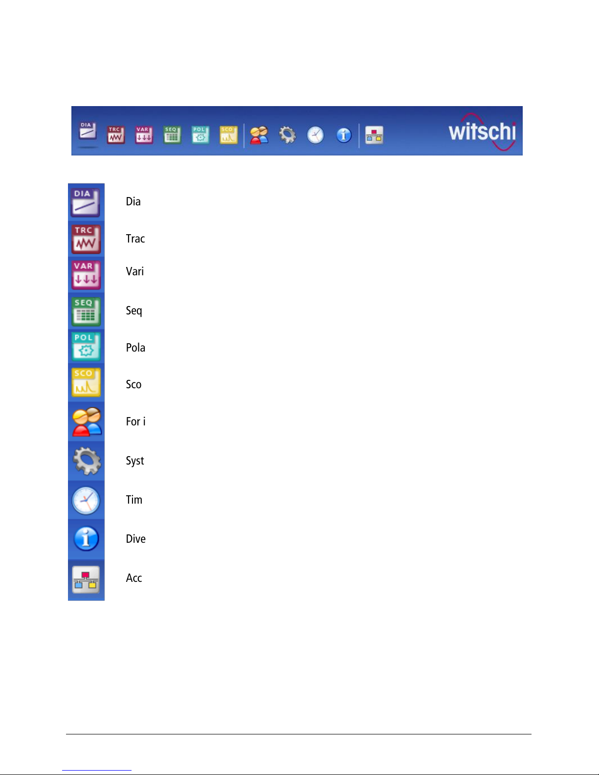
4.3 LATERAL TOOLBAR ....................................................................................................... 12
5DISPLAY MODES ....................................................................................................... 14
5.1 DISPLAY MODE DIAGRAM ............................................................................................. 14
5.2 TRACE DISPLAY MODE .................................................................................................. 14
5.3 VARIO DISPLAY MODE .................................................................................................. 15
5.4 SEQUENCE DISPLAY MODE ............................................................................................ 15
5.5 POLAR DISPLAY MODE.................................................................................................. 17
5.6 SCOPE DISPLAY MODE .................................................................................................. 19
5.7 INPUT OF CLIENT ADDRESS AND PIECE INFORMATIONS........................................................ 20
................................................................................................................................. 21
5.8 TIME,DATE AND MOON PHASE ...................................................................................... 21
5.9 INFORMATION ............................................................................................................. 21
................................................................................................................................. 22
5.10 EXPORT SCREEN CONTENT.............................................................................................. 22
5.11 ERROR MESSAGES ........................................................................................................ 22
6DISPLAY/EDIT MEASUREMENT PROGRAMS ............................................................... 24
6.1 TAB PROGRAM ............................................................................................................ 25
6.2 TAB DIAGRAM............................................................................................................. 26
6.3 TAB TRACE AND VARIO ................................................................................................. 26
6.4 TAB SEQUENCE............................................................................................................ 27
6.5 TAB POLAR ................................................................................................................. 27
6.6 TAB TOLERANCES......................................................................................................... 28
7SYSTEM PARAMETERS .............................................................................................. 29
7.1 TAB SYSTEM................................................................................................................ 29
7.2 TAB TIME ................................................................................................................... 31
7.3 TAB PROGRAM ............................................................................................................ 32
7.4 TAB SECURITY ............................................................................................................. 32
7.5 TAB MEASUREMENT ..................................................................................................... 33
7.6 REITER DIAGRAMM ...................................................................................................... 33
7.7 TAB TRACE /VARIO...................................................................................................... 34

Page 4/39 Chronoscope X1 (G3) Witschi Electronic Ltd
7.8 TAB SEQUENCE ............................................................................................................34
7.9 TAB SCOPE ..................................................................................................................35
7.10 TAB WICOTRACE AND NETWORK ....................................................................................35
8MAINTENANCE AND CUSTOMER SERVICE................................................................. 36
8.1 GUARANTEE ................................................................................................................36
8.2 MAINTENANCE.............................................................................................................36
8.3 CALIBRATION ...............................................................................................................36
9TECHNICAL DATA...................................................................................................... 37
9.1 DECLARATION OF CONFORMITY.......................................................................................39
10 ACCESSORIES ............................................................................................................ 39

Witschi Electronic Ltd Chronoscope X1 (G3) Page 5/39
1SAFETY REFERENCE
Please read carefully all the information contained in this manual and
strictly follow the operating instructions, which will help you to use and
safely operate our product. Keep this manual in a safe place near the
instrument and give it to any other user.
The facility must be used only for the aims and purposes described in this very manual and must be
set up and operated as described and under the conditions herein specified.
The Manufacturer, Witschi Electronic AG in CH - 3294 Büren a.A. Switzerland takes no
responsibility and offers no warranty for damages that may follow from the non-observance of these
directives or from inappropriate handling, such as damages to the checking device, to watches
and/or people!
1.1 Recycling
This electronic instrument should not be disposed of as household refuse. If it is not accepted by
public collecting points, kindly bring it back to the sales outlet. It will provide suitable disposal
according to legal directives. Your equipment suppliers in the EU will take back free of charge all
instruments manufactured after the 13.8.2005, as well as an older instrument provided an
equivalent new instrument is purchased.

Page 6/39 Chronoscope X1 (G3) Witschi Electronic Ltd
Congratulations
You made the right choice.
You bought CHRONOSCOPE X1 (G3), an extremely accurate test instrument, technically reliable as
well as easy to handle and operate.
Follow the given instructions regarding usage and maintenance and you will enjoy this new
instrument for quite a long time. It will be a pleasure and will prove profitable for you to use this
device.
2DESCRIPTION
The Most Recent Technology for Testing Mechanical Watches
The Chronoscope X1(G3) is the top-of-the-line instrument to be used during manufacturing, by
the repair service or in the watch-testing lab. It includes the terminal X1 (G3) with a 10.4" colour
touch screen and the automatic Micromat C microphone with integrated Chronoscope
measurement electronics. It provides 6 different display modes as well as a graphical
representation of beat noises.
The large touch screen provides an extremely intuitive and straightforward operation.
Particular Features:
–– Screen capture (camera function)
The current content of the screen is stored in PNG format into a plugged-in USB memory stick
when the camera key is pressed.
–– Picture presentation
Up to 99 pictures in JPG format can be stored for the start/stop screen saver. The slide show
runs at a rate of a new picture every 10 seconds.
–– Client Address and Piece Information’s
Via menu point easy input of client addresses and piece information’s. If desired, the selected
data appears on the printout and as header in the captured print screen as PNG file. The client
addresses and piece information’s can be stored and retrieved in a list.
–– Display of the moon phase
In display mode time and date is also the moon phase symbolically presented, with following
information’s: number of days since last new moon, last new moon, full moon and next new
moon.

Witschi Electronic Ltd Chronoscope X1 (G3) Page 7/39
3INSTALLATION
3.1 Extend of delivery
The basic equipment comprises the following components:
X1 (G3) Terminal with colour Touchscreen
Pen for Touchscreen
Universal AC-Adapter 100 –240 V~ for Terminal X1 (G3)
Printer cable for Witschi printer
Microfiber cloth 23x23 cm
Dust proof cover for Terminal X1 (G3)
Automatic microphone Micromat C
Mains adapter for 230 V~ or 120 V~
USB cable
Dust proof cover for Micromat C
Certificate of guarantee, installation guide, operating manuals (5 languages)
3.2 Setting up the instrument
Warning:
When installing the device, avoid direct proximity to very high temperatures and direct exposure to
the sun which negatively influences the readability of the display. Loud noises impair the signal
reception of the microphone, which must obviously be kept at a reasonable distance from noisy
machines, loudspeakers and particularly from ultrasonic cleaning equipment.
3.2.1 Mains connection
Power is supplied to the X1 (G3) Terminal through the universal AC-adapter for a mains voltage of
100 –240 V~. The power supply for the Micromat C occurs through a for a mains adapter for a
mains voltage of 230 V~ (range 210 V~ - 240 V~) or for 120 V~ (range 110 V~ - 130 V~).
Before connecting for the first time, make sure that the voltage of the mains
adapter corresponds to the voltage of your mains
.
Use only Original Adapter!
Connect the mains adapters to the suitable sockets on the rear panel and connect the X1 (G3) Terminal
with the Micromat C by means of the USB-wire. If present, connect also the thermo printer 740RS232
(available as accessory).
See chapter
3.3 Connections
, page 7.
We recommend disconnecting the power supply from the mains during longer idle periods, e.g.
vacations.

Page 8/39 Chronoscope X1 (G3) Witschi Electronic Ltd
3.3 Connections Terminal X1 (G3) –Micromat C
Terminal X1 (G3)
USB 1, USB 2, USB 3
USB interfaces for Micromat C and memory stick, Bluetooth-Dongle,
computer-mouse etc.
µSD
Slot for Micro SD card
COM 1
Interface for Thermal printers
Connect printer only to COM 1 interface!
Ethernet
Network-interface.
12-24V
Connection socket for universal adapter 100 to 240 V, 1.5A 50-60Hz
Main switch for switching the equipment on / off
Micromat C
9V~ / 1.2A
Connection socket for mains adapter, 230 V~ or 120 V~
USB Interface for X1 (G3) Terminal
Connection socket for earphone (accessory)
microphone
Connection socket for stand microphone (accessory)
O 1
Main switch for switching the equipment on / off

Witschi Electronic Ltd Chronoscope X1 (G3) Page 9/39
4OPERATING
Place the watch to be tested on the microphone in such a way that the crown lies between the
metal leads of the signal sensor.
The LED
signal
flashes in the rhythm of the beats of the watch, thus showing that watch’s signal is
received. The tracing of the diagram starts automatically.
4.1 Touch Screen
When it is switched on, the Chronoscope X1 (G3) goes back to the same measuring mode it was in
before being switched off.
The large buttons on the touch screen are activated by touching them with a finger or the pen.

Page 10/39 Chronoscope X1 (G3) Witschi Electronic Ltd
4.2 Menu Bars and Buttons
The buttons around the main screen are placed on menu bars ordered by functions
Diagram display mode
Trace display mode
Vario display mode
Sequence display mode
Polar display mode
Scope display mode
For input of customer and watch data, comments etc.
System parameter
Time, Date and Moon phase
Diverse information’s
Access to the WiCoTrace data base, when the device is connected to the network

Witschi Electronic Ltd Chronoscope X1 (G3) Page 11/39
Toolbar for the Scope system parameter setting
Mode: Scope 1
Toolbar for the Scope system parameter setting
Mode: Scope 2
Display of the current program number in the selected colour.
This button opens the overview of all programs.
The next or previous program is selected with the
plus
and
minus
buttons; a longer
contact with the button automatically increments or decrements the program number.
The amplification value as well as the zoom can also be adjusted with
plus
and
minus
buttons.
Program selection
button: for adjusting individual measurement parameters of a
selected program. A complete list of the programs can be called upon for this purpose.
Button for switching on/off the
Averaging
mode. Active only in test mode
Scope 2
. See
chapter
5.6 Scope Display Mode
, page 18
Speaker
button: for switching on and off the audio output of the Micromat C.
Camera
button: When this button is pressed, a copy (PNG file) of the screen content is
loaded onto a USB stick, if plugged in. Data are stored in the directory
“Witschi\Chronoscope_X1\Capture” under the file name “Snapshot_NN.png”. NN is
incremented from 01 to 99.
Print
button: The current view can be printed on the Witschi thermal printer while the
measurement process is running.
The current amplification value is indicated in the sector
Amplificat
. It can be adjusted with the plus
and minus buttons. The selected program does not automatically use the amplification set-up. A
lasting modification must be carried out in
Program selection
.

Page 12/39 Chronoscope X1 (G3) Witschi Electronic Ltd
Important information:
By touching the "Amplificat." surface, the lift angle and test mode functions can be directly selected.
With the buttons and you can adjust the appropriate parameters. The selected function and
the parameter setting are displayed on a yellow background.
4.3 Lateral Toolbar
-
Stop
button: For pausing a measurement
Start
button: For measurement start or continue
Reset
button: The current measurement is restarted,
except in SEQ test mode
-
Left
button: The function varies according to the display
mode being selected
Right
button: The function varies according to the
display mode being selected
-
Positions
buttons: Display of the current test position. Any test position
can be directly selected by clicking on the suitable button. The MMC
then switches to the desired position. The measurement is interrupted
during the rotation. Switching from one test position to another can
also be carried out with the joystick on the MMC.
-Remark
In the test mode “Sequence” only 6 positions are displayed, if the
measuring cycle contains no intermediate test positions.

Witschi Electronic Ltd Chronoscope X1 (G3) Page 13/39
Indication of the test positions in accordance with NIHS 95-10/ISO 3158
Current indication of the test positions

Page 14/39 Chronoscope X1 (G3) Witschi Electronic Ltd
5DISPLAY MODES
5.1 Display Mode Diagram
Measured values for rate deviation and
beat error are continuously displayed during
the measurement process. The slope of the
diagram can be changed (1, 2, 4, 8 and 16
times) by pressing the
plus
and
minus
buttons (zoom).
Measured values for rate deviation, ampli-
tude and beat error are displayed numeri-
cally. The last measured result remains
displayed when measurements are paused.
The last eight pages are shown as small
format strips under the current diagram if
measurements have been performed for a
long enough time. If measurements are paused, one of the last pages can be selected with the
left
and
right
buttons. The desired page can also be displayed in a large format by directly touching it.
5.2 Trace Display Mode
This display mode is combined with the
Vario display mode. It is possible to switch
between the two modes during
measurement or during a pause.
The rate deviation and the amplitude are
contiguously recorded. The
plus
and
minus
buttons allow zooming in and out (1 to 8
times).
Measured values for rate deviation, ampli-
tude and beat error are displayed numeri-
cally. The last measured result remains
displayed when measurements are paused.
The means are numerically displayed at the
end of the measurement time.

Witschi Electronic Ltd Chronoscope X1 (G3) Page 15/39
5.3 Vario Display Mode
The Vario display mode measures the rate
and amplitude stability over a longer time
range.
The following measured values related to
rate and amplitude is continuously up-dated
during the measurement process: smallest
and largest measured values, mean,
standard deviation, elapsed measurement
time and current measured value.
Measured values for rate deviation, ampli-
tude and beat error are displayed numeri-
cally. The last measured result remains
displayed when measurements are paused.
The means are numerically displayed at the end of the measurement time.
Checking the rate quality:
The evaluation of the quality takes place via the interpretation of the 2 analysed rate values.
-The difference between the minimum and the maximum rate value, presented with the
vertical arrows, is a quality indicator of the watches condition. The smaller the difference the
better is the rate stability.
-The average value X is an indicator for the adjustment quality of the watch movement.
-σ(Sigma) shows the standard deviation ( 68.2%) of all instantaneous rate and amplitude
measurements. (1 Sigma = +/- 34.1% = 68.2%)
5.4 Sequence Display Mode
A measurement cycle including up to 10 test
positions can be defined in this mode. The
measurement cycle can also be started from
Micromat C.
The
left
and
right
buttons allow selecting
one of the Diagram, Trace, Vario and
Sequence formats during or after the
measurement cycle.
The following measurement results are
calculated for rate, amplitude and beat
error:
-Mean for each test position
-X: Mean of all test positions
-D: Difference between the largest and the smallest measured value.
-DVH: Only for rate and amplitude. Difference between the mean of all vertical test positions
and the mean of all horizontal test positions.
-Di: Only for rate. Difference between the 6H and CH test positions.

Page 16/39 Chronoscope X1 (G3) Witschi Electronic Ltd
-DVm:
Standardized rate difference proportionally to the size of the unbalance. I.e. theoretical
maximum rate difference causes by the unbalance of the balance wheel, at an amplitude of
270°, in the two vertical positions where the unbalance is down or above on the vertical.
-Φ:
Watch is in vertical position. Shows the place of the unbalanced point on the balance wheel
(flash)
I.e. The rotation angle of the stem refers to the 3H position.

Witschi Electronic Ltd Chronoscope X1 (G3) Page 17/39
During the course of a measurement cycle,
the test position and measured rate accuracy
will be displayed.
After an elapsed measurement cycle appears
in “Diagram” display mode the test positions
with its numerical measuring values of rate
accuracy, beat error and amplitude.
5.5 Polar Display Mode
POLAR display mode indicates the rate stability in a polar diagram. One revolution (rotation time) of the
Tourbillon watch corresponds to one revolution on the diagram. The average values of rate, beat error
and amplitude for specific angles are calculated and displayed. The watchmaker can now determine the
centre of gravity of the balance wheel.
First, the desired start position (9H, 6H, 3H or
12H) must be selected. By pressing the
start
button on the MMC the start position
6H is automatically approached.
Upon reaching the start position, the
stabilisation time must be awaited before
starting the measuring cycle (i.e. 30 seconds
stabilisation at a rotation time of 60
seconds= half turn of the Tourbillon cage).
Then start the cycle with:
-
start
button on the MMC or
- button on the X1

Page 18/39 Chronoscope X1 (G3) Witschi Electronic Ltd
Important!
The measurement time should be at least the
tourbillon rotation time. Recommended is a
measurement time that corresponds to five
full tourbillon rotations (see chapter 6.5vv,
page 26).
The first result is automatically assigned to
the value P000. Thus, the measurement can
be repeated again and again, the user must
define a starting point based on the visible
balance wheel and the trigger the
measurement always in same condition (Fig.).
With the two arrow buttons you can toggle
between the displays of rate accuracy and amplitude.
Results:
-P000: Average value of the results at the star of the measurement
-P090: Average value of the results after a 90° rotation of the tourbillon cage
-P180: Average value of the results after a 180° rotation of the tourbillon cage
-P270: Average value of the results after a 270° rotation of the tourbillon cage
-Xv: Average value of the four results P000, P090, P180 and P270
-Xp: Average value of all results of the total measurement time

Witschi Electronic Ltd Chronoscope X1 (G3) Page 19/39
5.6 Scope Display Mode
Mode: Scope 1
The acoustic beat noise of the watch is
graphically shown in this mode. A tick and
a tock are always alternatively shown.
A time range of 20 ms, 200 ms or 400 ms
can be selected with the
left
and
right
buttons.
The last eight beat noises are shown as
small format strips under the current beat
noise if measurements have been
performed for a long enough time. The
desired beat noise can also be displayed in
a large format by directly touching it.
Mode: Scope 2
In this mode the averaging can be
switched on and off with the button. The
time range is fixed at 20 ms. Presentation
of the beat noises (tic and tac) on two
horizontal axes.
When the averaging mode is turned off,
the beat noises are continuously recorded.
When the averaging mode is turned on,
the graphical presentation of a certain
amount of beat noises is averaged.
Picture 3 Picture 5
The duration of the measurement cycle is determined by the beat number and the selected interval.
He is finished after 50 Tic and 50 Tac intervals. Then the average value of the amplitude is displayed
on each horizontal axe. It cannot be said on which horizontal axe the Tic or the Tac is assigned.
When you click on Picture 3 the average value after 10 intervals is displayed, and for Picture 5 after
20 intervals.
The Averaging of the signal is a process, by which the noise can be reduced in repetitive signals. By
additive superposition the signal is thereby increased, while the superposition of random noise leads
to no gain. Overall, the signal-to-noise ratio is improved.

Page 20/39 Chronoscope X1 (G3) Witschi Electronic Ltd
5.7 Input of Client Address and Piece Informations
Here you can store client addresses and piece information’s. You can choose None , Standard or
Extended
The relevant information’s will appear as header on the exported screen contents and on the printing
protocol if the Standard or Extended is enabled.
Possible input options in Standard mode
Piece: 24 character
Line 1, 2. 3: 24 characters/each
Delete the displayed piece information’s.
Save and load of piece information’s is only
available in Extended mode.
Possible input options in Extended mode
Guarantee: Yes or No
For all other input fields
24 characters/each.
In this mode you can save client addresses and
piece information’s data or open saved client
addresses and piece information’s.
Delete the displayed client address or the
piece information’s.
Save Client Address and Piece Information’s
Push on to display the "Save Client Address" or the “Save Piece information’s” window.
Select from the list one unassigned Client Address or Piece informations (01: to 99:) and press Take
over
You may also select an occupied address number and overwrite it.
Load Client Address and Piece Information’s
Push on to display the "Load Client Address" or the “Load Piece information’s” window.
Select from the list the desired Client Address or Piece information’s (01: to 99:) and press Take over
The loaded Client Address with the associated Piece information can also be edited.
Table of contents
Other Witschi Measuring Instrument manuals