SATAM 7887 Series Owner's manual

SATAM Siège Social : Paris Nord II – 5, rue des Chardonnerets
Usine de Falaise – Avenue de Verdun – B.P. 129 – 14700 FALAISE – France B.P. 85012 – Tremblay- en-France – 95931 Roissy C.D.G. Cedex - France
Tél. : +33 (0)2 31 41 41 41 Tél. : +33 (0)1 49 90 77 00
Fax : +33 (0)2 31 40 75 61 Fax : +33 (0)1 49 90 77 99
SIRET 495 233 124 000 17 SA au capital de 6 037 000 € – RCS Bobigny B 495 233 124
CODE APE 2813 Z SIRET 495 233 124 000 17 – Code APE 2813 Z – N° TVA : FR 48 495 233 124
MECHANICAL REGISTER SERIE 7887
MANUAL
DESCRIPTION - INSTALLATION – OPERATION -
SERVICING
U508218-e – Revision 02 – 24 February 2009
This document consists of 17 pages, including the flyleaf
This document is the property of SATAM
And may not transmitted to third parties without prior authorisation
SATAM may modify this document without prior authorisation
In conformity with the European directive 94/9/CE-ATEX

Edition du 24/02/09 / 17 U508218-e Revision : 2
2
Summary
1. INTRODUCTION .............................................................................................................................................. 3
1.1. GENERAL.............................................................................................................................................. 3
2. SERIES 7887 DESCRIPTION ........................................................................................................................... 4
2.1. GENERAL................................................................................................................................................... 4
3. PERIODIC INSPECTION.................................................................................................................................. 6
3.1. GENERAL................................................................................................................................................... 6
3.2. DISASSEMBLY PRIOR TO CLEANING.................................................................................................. 6
3.3. CLEANING. ................................................................................................................................................ 6
3.4. INSPECTION. ............................................................................................................................................. 6
3.6. TROUBLESHOOTING............................................................................................................................... 8
4. DISASSEMBLY AND ASSEMBLY................................................................................................................. 9
4.1. GENERAL................................................................................................................................................... 9
4.2. REMOVAL OF MAJOR GROUPS............................................................................................................. 9
4.3. INDIVIDUAL PARTS REPLACEMENT................................................................................................. 11
4.4. INSTALLATION OF MAJOR GROUPS ................................................................................................. 12
4.5. FINAL CHECKS AND ADJUSTMENTS. ............................................................................................... 16
4.6. OPERATIONAL CHECK. ........................................................................................................................ 17
4.7. IMPORTANT REMARKS........................................................................................................................ 17

Edition du 24/02/09 / 17 U508218-e Revision : 2
3
1. INTRODUCTION
1.1. GENERAL
These instructions are for servicing the Series 7887 Meter Registers.
Every Meter Register is thoroughly tested at the meter factory when installed on the meter. However,
like any precision mechanism, it requires periodic care to ensure maximum service. This manual is for
use in areas where factory rebuilding facilities and adequate exchange stocks are not readily
accessible.
Where manufacturer's replacement stocks are available, it is important that no attempt be made to
repair any meter register defective within the terms of the warranty as by doing so, the warranty is void
and the user is deprived of the protection provided by the warranty. It is recommended that, when
possible, meter registers be replaced and the defective unit returned to the meter manufacturer.

Edition du 24/02/09 / 17 U508218-e Revision : 2
4
Figure 1. External View of Series 7887 Meter Register.
2. SERIES 7887 DESCRIPTION
2.1. GENERAL.
1. Physical. The Series 7887 Meter Register,
Figure l, displays a running account, final total
and accumulated total of the quantity of liquid
product delivery. Contained in a 4" x 10" die
cast enclosure, individual delivery data is
displayed on five 3/4" high figures while
totalizer information is recorded on eight 1/8"
high figures. Reset of the Meter Register is
accomplished through a reset knob on the
right-hand side of the unit.
2. Operational. The Meter Register is operated
by a drive shaft connected to a group of gears
on the gear plate which converts the drive
revolutions to the appropriate ratio. The output
bevel gear of the group drives a bevel gear,
Figure 5, which is connected to the drive shaft
and clutch assembly. In rotating, this shaft
drives a gear on the clutch assembly which in
turn drives a gear on the right (unit) wheel
assembly. Revolutions are then accumulated
on the wheels. In addition, this rotating shaft
drives the bracket group connected to the
accumulative totalizer shaft, thus both displays
are driven from the same source, assuring
accurate recording of information. During the
reset operation, the clutch is disconnected
from the drive shaft, a shutter moves into place
covering the display wheels and reset fingers
engage heart-shaped cams on the individual
wheels to move them back to a zero position.
ln addition, a set of anti-topping fingers
engages the wheels to prevent jamming. At the
completion of reset, the display wheels will
read aIl zeros, and the shutter will rise to the
normal operating position. The clutch will
engage the drive shaft to transfer the
information from the next delivery. The totalizer
wheels will be unaffected by this reset
operation, thug displaying an accurate
measure of the accumulated totals of many
deliveries.
2.2. SPECIFICATIONS.
Specifications listed are standard unless
otherwise noted. Option al features are
available at additional cost.
Speed: 250 rpm.
Torque: Average running torque at room
temperature with 1:1 input: 4 oz-in. During
display wheel transfer from a119's to aIl O's,
the instantaneous peak torque may reach 40
oz-in.
Operating Temperature Range: -400 to
+71°C (-400 to +160°F).
Number of Figures: Meter Register: 5.
Accumulative Totalizer: 8
Size of Figures: Meter Register: 0.750" high x
0.400" wide (19.05 x 10.16 mm). Totalizer:
0.125" high x 0.078" wide (3.175 x 1.98 mm).
Colour of Figures: White on black, except
right-hand totalizer wheel which is black on
white when recording tenths of units, and white
on black when recording whole units.
Style of Figures: Veeder-Root/Cornell for
optimum read- ability.
Character Configuration :J:)-to 9 (options
available).
Reset: Single handle on register. Designed for
one-handed operation.
Mounting: Eight 1/4 x 28 tapped holes with
steel inserts on a 6.625" (168.28 mm)
diameter. Special adapters are available for
nearly ail meters.
Construction: Cover: cast aluminium. Case
and sub frame: cast Zamak. Wheels, pillions,
and clutch: acetal resin.
Gearing: 1:1 is standard. 1:1 through 42:1 are
available.
Lubrication: Periodic.
OPTIONS :
Non reset Pulser : Meter Register with Series
1871 or 7671 Pulse Transmitter.

Edition du 24/02/09 / 17 U508218-e Revision : 2
5
Figure 2. internal View of Series 7887 Meter Register
Figure 3. Mounting Dimension

Edition du 24/02/09 / 17 U508218-e Revision : 2
6
3. PERIODIC INSPECTION
3.1. GENERAL.
The Meter Register is fully lubricated and properly
adjusted at manufacture. However, periodic
cleaning a}\d lubrication are required.
Judgement of the intervals at which the meter
register requires such service must necessarily be
left to the individual user due to varying conditions
of service. Under normal conditions, this will be at
least once a year, or after each 2-1/2 million units of
measure delivered, whichever comes first.
3.2. DISASSEMBLY PRIOR TO CLEANING.
Remove the meter register from its housing as
follows:
1. Remove the bolts securing the cover (if present)
to the top of the housing. These bolts are hex head
and are located at the four corners of the bottom of
the housing. Remove the cover.
2. Remove the three button-head bolts securing the
meter register to the housing. Remove the meter
register.
3. Remove the screws securing the gear plate to the
bottom of the housing. Remove the gear plate.
3.3. CLEANING.
CAUTION: DO NOT USE A WIRE BRUSH.
1. Wipe bezel crystal with a clean lint-free rag.
2. If the wheel faces are dirty, gently clean with a
clean lint-free rag dipped in mild soapy water.
3. Clean the gears on the base plate by flushing or
with a brush dipped in solvent. Blow dry with
compressed air.
4. Clean Housing by dipping, flushing or brushing
with solvent. Blow dry with compressed air.
3.4. INSPECTION.
A periodic inspection of the en tire meter register,
housing and gear plate is required to make sure that
they function properly, parts are in place, and no
binding or excessive side-to-side motion of shafts
occurs. A checklist on such procedures follows:
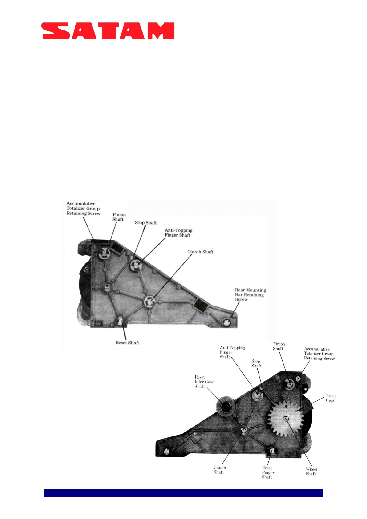
1. Check the following shafts for perceptible side-to-
side motion.
Note: Remove the meter register from the housing
before checking shaft freedom.
a. Wheel Shaft
b. Anti-Topping Finger Group Shaft
c. Reset Finger Group Shaft
d. Clutch Group Shaft
e. Pinion Shaft
2. Temporarily install the base plate and meter
register in the housing and check for proper
engagement and freedom of movement of:
a. AlI gears on gear plate.
b. Output bevel gear on gear plate with the bevel
drive gear on drive shaft.
c. 57 tooth gear on clutch assembly with gear on
right wheel assembly.
d. Gear drive shaft with gear train that operates the
totalizer, and gear connecting the drive train to the
totalizer.
3. Rotate drive shaft by hand to see that unit
operates freely and then reset, checking for proper
reset and shutter action. Adjust pointer alter reset as
required.
4. Check ail screws, retaining rings and groove pins
to see that they are tight and seated properly.
3.5. LUBRICATION.
1. Recommended Lubricants
Note: Chemlube and Vischem products are
manufactured by Ultrachem Inc.,
1400 N. Walnut St., P.O. Box 2053
Wilmington, DE 19899
Oil: Chemlube 201 or equivalent with a temperature
range of -65°F to +275°F (-54°C to + 135°C).
Grease: Vischem 352 or equivalent with a
temperature range of -65°F to +3000F (-MOC to +
149°C).
Note: All lubricants used in the register must be of a
type which remains fluid over the full temperature
range to which the register will be subjected. Also,
they should not oxidize or dry out leaving a gummy
or perceptible residue.
If the Chemlube 201 oil lubricant is not available, a
substitute with equivalent properties may be used.
To assist field personnel in obtaining suitable
lubricants for the meter register and ticket printers,
the following list showing equivalent lubricants has
been prepared: OIL
AEROSHELL FLUID NO. 3
REGENT SPINTEX OIL 60
GARGOYLE ARCTIC OIL LIGHT
CASTROL HYSPIN 40
ANDEROL 40lD
GREASE
AEROSHELL 14
ESSO BEACON 325
ANDEROL 795
2. Points to Lubricate
Oil: Ali points indicated as "Oil" on Figure 6 should
be lubricated with oil as described above. This
includes ail shafts, studs, and bosses on which a
moving part bears.
Grease: Grease should be applied to ail points
indicated as "Grease" on Figure 6. This includes
gears and the no-back ratchet and pinion.
Note: The oil and grease should be applied with a
small brush to make certain that ail areas will be
properly lubricated. In this manner, the amount of
lubricant being used will be more easily controlled.

Edition du 24/02/09 / 17 U508218-e Revision : 2
7
Figure 4. Lubrification Points

Edition du 24/02/09 / 17 U508218-e Revision : 2
8
3.6. TROUBLESHOOTING.
Table 1 is used to assist in locating problems and making repairs and corrections. In some problems,
similar defects can be produced by several causes of an entirely different nature. Cause of the trouble
must be determined and the correction made.
Table 1. Troubleshooting
TROUBLE
POSSIBLE CAUSE CORRECTION
1. Drive shaft hard to turn Pointer or brake rubbing on first wheel.
Dirt or pieces of foreign material in
teeth of drive shaft gears, gear plate,
totalizer or bevel gear train driving
totalizer
Check pointer and break positioning.
Adjust as required.
Remove case. Check all gears, clean
and lubricate as necessary. See
Section
3.
2. Binding occurs during reset
cycle. Missing washers on outside of clutch
shaft.
Pinion jam, anti-topping finger( s)
broken or spring(s) missing.
Check end play and washer as
required.
Check end play of wheel shaft.
Replace broken anti-topping fingers or
missing
springs.
3. Reset knob turns hard Reset knob flange on the case binds
on reset shaft.
Wheel shaft group is bent.
Reset fingers rubbing on wheel or
retaining rings.
Remove reset knob. Loosen flange
screws, center the flange on the shaft
and tighten the screws.
Replace wheel shaft.
Check for missing retaining rings on
reset finger and wheel shafts. Replace
as required.
4. Any one wheel will not
reset to zero Broken reset finger.
Locking disc pin out of wheel groove.
Replace reset fingers as required.
Disassemble wheel group and insert
locking disc pin into groove in wheel.
5. Incomplete reset cycle.
Knob turns but reset does
not occur.
Key in large multiple cam broken.
Reset actuating lever not engaged m
cam or reset arm broken.
Replace cam with new cam and key.
Remove cam, inspect and replace
parts as required, and assemble
properly.
6. Shutter partially obscured
wheels at completion of
reset cycle or completely
covers wheels at end of
reset cycle.
Shutter disconnected from reset lever.
Connect shutter to reset lever.
7. Shutter will not drop into
place or loss of detent
action during reset.
Detent lever spring missing or broken. Install new spring
.
8 Pointer not aligned with unit
wheel. Improper adjustment of brake or
pointer. Adjust brake to proper clearance.
Adjust pointer to center mark
.
9. Unit wheel can be turned in
reverse by hand. Dirty drive shaft clutch assembly. Clean clutch group and lubricate. See
Section 3.
10. Cannot drive meter
register. Pinion jam, reset fingers are engaged,
heart cams hit on detent lever shutter
stud, clutch not engaged
.
Check washers on pinion shaft. Check
end play of shafts. Clean and lubricate
clutch.

Edition du 24/02/09 / 17 U508218-e Revision : 2
9
4. DISASSEMBLY AND ASSEMBLY
4.1. GENERAL.
When disassembling the meter register, be
extremely careful not to lose or intermix any of
the washers round on the shafts. By doing so,
potential problems with end-play and backlash
adjustments will be greatly lessened. When
removing retaining rings or other parts from
shafts, do not hold the shaft with any tool that
might gouge or create burrs on the shaft.
4.2. REMOVAL OF MAJOR GROUPS.
Instructions for removal of aIl shaft groups are
provided.
1. If present, remove the retaining ring
securing the reset idler gear to the reset idler
gear shaft.
2. Remove retaining rings and washers
securing the pinion, reset, anti-topping and
clutch shafts to the right-hand side plate
(Figure 7). Remove screws and lockwasher
securing the totalizer group and rear mounting
bar tram right-hand side plate.
3. Remove side plate.
CAUTION: DO NOT LOSE OR INTERMIX
WASHERS FROM EACH SHAFT.
Note: Remove only those shaft groups
necessary to gain access to parts being
replaced.
Figure 5. Right -Hand Side Plate.
Figure 6. Left -Hand Side Plate.

Edition du 24/02/09 / 17 U508218-e Revision : 2
10
4. Clutch Shaft Group Removal.
a. Remove retaining ring and washers securing
the clutch shaft group to the left-hand Bide plate.
See Figure 6.
b. Move clutch lever group so clutch is free. See
Figure 7. Remove clutch shaft group. See
Paragraph C, 1 for parts replacement.
5. Reset Finger Group Removal.
a. Remove retaining ring and washer securing
the reset group to the left-hand Bide plate. See
Figure 6.
b. Disengage the reset fingers and no-back pawl
from the wheels. See Figure 8. Remove the
group. See Paragraph C, 2 for parts
replacement.
6. Stop Shaft Removal.
a. Remove the springs from between the anti-
topping fingers and the stop shaft.
b. Remove the spring from between the detent
lever group and the stop shaft.
c. Remove the stop shaft.
7. Anti-Topping Finger Group Removal.
a. Remove the retaining ring and washers
securing the anti-topping finger group shaft to
the left-hand Bide plate. See Figure 6.
b. Disengage the anti-topping fingers and the
clutch lever group from the wheels. See Figure
9.
c. Remove the group from the Bide plate. See
Paragraph C, 3 for parts replacement.
8. Totalizer Group Removal.
a. Remove the screws securing the totalizer
group to the left-hand and right-hand Bide
plates. See Figures 5 and 6.
b. Remove the totalizer group.
c. No addition al disassembly of the totalizer is
possible. If the totalizer is inoperable, replace
the group.
Figure 7. Clutch Group Removal.
Note: If the inoperable totalizer has a small bevel
gear (approx. 11/32 inch dia.) on the drive shaft,
replace the bracket group on the left side frame as
well as the totalizer group (see Figure 29 and
Paragraph D, 7 and E, 5). Remove the screw
holding the pointer onto the old totalizer and save
for installation on new totalizer.
9. Pinion Removal.
a. Remove retaining ring securing pinion shaft to
the left hand side plate. See Figure 6.
b. Rotate the detent lever group so it will clear
the reset cam. Remove shaft.
c. Remove pillions, detent lever group washers
and retaining rings from shaft.
10. Wheel Group Removal.
a. Mark relationship of reset gear to wheel group
shaft to assure proper positioning during
assembly.
b. Remove pin securing reset gear to the wheel
group shaft.
c. Remove gear, retaining ring and washer.
Remove shaft. See Paragraph C, 4 for parts
replacement.
Figure 8. Reset Finger Group Removal.
Figure 9. Anti-Topping Finger Group Removal.

Edition du 24/02/09 / 17 U508218-e Revision : 2
11
4.3. INDIVIDUAL PARTS REPLACEMENT
1. Clutch Shaft Parts Replacement. See Figure 10.
a. Totalizer and Drive Bevel Gears.
(1) Drift out pin securing gear to shaft. (2)
Remove gear.
(3) Remove retaining rings and washers that
position drive gear. Do not change the
order of the rings and washers.
(4) Drift out pin holding drive gear and
remove gear.
(5) Install new gear, pin, retaining rings and
washers. Use new pin if required.
(6) Install totalizer bevel gear and secure
with pin.
CAUTION: CHECK SHAFT FOR STRAIGHTNESS
AFTER PINNING. A BENT SHAFT WILL
CAUSE BINDING DURING DRIVING OF
METER REGISTER. CLUTCH MUST NOT
BE DISASSEMBLED OR REPLACED AS
AN INDIVIDUAL GROUP. IF CLUTCH IS
BROKEN OR MALFUNCTIONS, REPLACE
COMPLETE SHAFT AND CLUTCH AS AN
ASSEMBLY.
2. Reset Finger Group Parts Replacement. See
Figure 11. Individual reset fingers, reset arm, no-
back pawl and pawl spring may be replaced as
required.
a. Remove retaining rings and appropriate
washer to reach particular part.
b. Replace defective items with new part.
Assemble remaining parts on shaft. Install
retaining rings and washers. Check end play
per Figure 26.
3. Anti-Topping Finger Group Parts Replacement.
See Figure 12. Individual anti-topping fingers,
reset lever and clutch lever may be replaced as
required.
a. Remove retaining rings, washers and parts as
required to get to part that is to be replaced.
b. Install parts, retaining rings and washers in
the sequence shown in Figure 12. Be sure to
install parts so they are in the proper
direction. Check end play per Figure 26.
4. Wheel Group Parts Replacement. See Figures
13, 14, 15 and 16. The reset cam, individual
wheels, locking discs and eccentrics may be
replaced as required.
a. Remove retaining rings, washers and key as
required to remove reset cam, wheels,
locking discs and eccentrics.
b. Install parts, retaining rings, washers and key
in the sequence shown in Figure 15. When
installing wheels, be sure the pin on the
locking disc engages the groove in the wheel
as shown in Figure 16. Check end play per
Figure 26.
Figure 10. Clutch Shaft Group
Figure 11. Reset Finger Group.
Figure 12. Anti-Topping Finger Group
.

Edition du 24/02/09 / 17 U508218-e Revision : 2
12
4.4. INSTALLATION OF MAJOR GROUPS
Prior to installing each shaft, lubricate per
Paragraph 5 in Section 3. During assembly, do not
intermix washers from one shaft to another.
1. Wheel Group Installation.
a. If not present, install a 0.030 inch thick washer
over the end of the wheel group shaft
opposite the cam.
b. Install the shaft into the proper hole in the left-
hand side plate. See Figure 6.
2. Anti-Topping Finger Group Installation. See
Figure 17.
a. Hold wheel and side plate assembly upside
down.
b. Install anti-topping finger group in proper hole
in left- hand side plate (see Figure 6). Be sure
aIl fingers and clutch lever are free of wheels
and the pin on the reset lever engages the
track on the cam.
c. Seat the shaft, install washers and retaining
ring to secure shaft to left-hand Bide plate.
d. See that aIl fingers are free to engage wheels.
3. Stop Shaft Installation.
a. install retaining rings on ends of shaft.
b. Insert stop shaft into proper hole in left-hand
Bide plate. See Figure 6.
4. Reset Finger Shaft Group Installation.
a. Rotate no-back pawl so that spring puts pawl.
under tension. Slip an elastic band over the
reset fingers and pawl to hold pawl in
position. See Figure 18.
b. Install shaft into left-hand side plate and
secure with retaining ring and washers. See
Figure 6.
c. Engage pin on reset lever group with slot in
reset afro. See Figure 20.
5. Clutch Shaft Group InstaIlation.
a. Install shaft in proper hole in left-hand Bide
plate. Add washers and secure with
retaining ring. See Figure 6.
b. b. Make sure that bevel gears that drive the
totalizer are free to turn.
Figure 13. Reset Cam Removal
Figure 14. Unit Wheel Removal
Figure 15. Locking Disc, Eccentric and Washer
Removal and Installation
Figure 16. Unit Wheel Installation.
Figure 17. Anti-Topping Finger Group Installation.

Edition du 24/02/09 / 17 U508218-e Revision : 2
13
6. Right-hand Side Plate Installation
a. Hold meter register assembly as shown in
Figure 20 and place a rubber band around
the assembly to hold it together. Be sure the
pin in the reset lever group remains
engaged in the slot in the reset afro.
b. Install side plate over wheel shaft first, then
engage the other shafts.
c. c. Temporarily secure the side plate to the
rear mounting bar with screws.
7. Bracket Group (if required) and Totalizer
Installation.
a. If required, install new bracket group to
inside of left side frame and secure with two
screws and lock- washers. See Figure 29.
b. Install pointer with screw (saved from old
totalizer) onto new totalizer group but do not
tighten screw securely. Pointer position
must be adjusted after totalizer group is
installed. See Paragraph F, 2.
c.
Install the totalizer group so that the bevel
gear is in mesh with the top bevel gear on
the bracket group and secure with retaining
screws. For adjustment of bevel gear drive,
sec Paragraph E, 5.
8. Spring Installation.
a. See Figure 21 for identification of springs.
b. Install the five anti-topping finger springs
between the anti-topping fingers and the
stop shaft. See Figure22.
d. Install the reset spring between the reset
lever and the pinion shaft.
e. Install the detent spring between the detent
lever group and the stop shaft.
f. e. Install the clutch spring between the
clutch lever group and the pinion shaft.
9. Pinion Shaft Assembly Installation
a. If not previously accomplished, remove all
parts from pinion shaft.
b. Rotate wheel shaft so reset fingers are fully
engaged in the heart-shaped cams on each
wheel.
g. Place pillions, with short finger up, in
between each wheel as shown in Figure 23.
h. d. Install the end of the shaft closest to the
two retaining ring slots into the left-hand
side plate and through each pinion.
Figure18. Reset Finger Shaft Group Preparation for
Installation Figure 20. Preparation For Side Plate Installation
Figure 19. Reset Lever Group Pin Engagement Figure 21. Spring Identification

Edition du 24/02/09 / 17 U508218-e Revision : 2
14
e. Install washers and detent lever group onto
shaft and engage shutter with tab on detent lever.
f. Push shaft through the right-hand side plate
and secure with washer and retaining ring.
g. Secure detent lever group into position with
retaining rings.
h. After assembly, rotate wheel shaft to make
sure all pillions have been positioned
properly. If binding occurs, reposition pillions
per step c.
10. Reset Gear Installation.
a. Install reset gear on wheel shaft, aligning
orientation mark made at disassembly.
b. Secure gear to shaft with pin.
11. Reset Idler Gear Installation.
a. If present, install reset idler gear on the reset
idler gear shaft. See Figure 6.
b. Secure with retaining ring.
Note: This gear will be timed when the meter
duplicator and meter register are assembled
together.
Figure 22. Anti-Topping Finger Spring Installation. Figure 24. Installation Of Meter Register Onto
Mounting Fixture.
Figure 23. Pinion Positioning. Figure 25. Securing Mounting Fixture.

Edition du 24/02/09 / 17 U508218-e Revision : 2
15
Figure 26. End Play Limits

Edition du 24/02/09 / 17 U508218-e Revision : 2
16
4.5. FINAL CHECKS AND ADJUSTMENTS
.
1. End Play Check: Check end play (back and forth
motion) of shafts and parts as follows:
a. For proper measurement, the meter register
must be installed in the TD-42383 mounting
fixture, Figure 24, to constrain the frame into
the same position that it is when installed in
the housing.
b. Secure the meter register to the fixture with
two 1/4-28 button-head bolts. See Figure 25.
c. Take end play measurements of each shaft.
Add or subtract washers as necessary to
obtain correct end play.
2. Input Drive Bevel Gear Engagement Adjustment.
a. Install the gear plate onto the fixture using the
appropriate hardware.
b. Remove the retaining ring behind the bevel
gear and add or subtract washers as required
for proper mesh between the bevel gear on the
gear plate and the drive bevel gear on the
clutch shaft. The shaft end play must be
maintained as specified in Figure 26.
c. Replace the retaining ring after adjustment.
3. Clutch Lever Positioning Adjustment.
a. Rotate the reset gear until the clutch is fully
disengaged.
b. Measure the clearances as shown in Figure
27.
c. If the dimensions cannot be obtained, add or
remove washers as required, or replace the
clutch and shaft.
d. The amount of face engagement between the
spur gear on the input clutch and the first
wheel should be 75%± 20%.
4. Wheel Brake Adjustment.
a. Rotate reset gear to position cam as shown in
Figure 28. b.
b. Measure clearance between brake and first
wheel. If clearance is not within the
dimensions given, adjust brake by loosening
screw and moving brake into position.
c. Remove the meter register from the fixture by
removing the two button-head screws.
Remove the gear plate from the fixture.
5. Gearing Adjustment for Totalizer. See Figure 29.
a. Loosen set screw on bottom bevel gear. Mesh
the top bevel gear tightly with the totalizer
bevel gear. Press the register clutch shaft
toward the left side frame. Adjust the bottom
bevel gear such that it has 0.012 -0.015 end
play when meshing with the clutch shaft bevel
gear. Tighten set screw and secure with a
sealant (Loctite 222 or equivalent) to prevent
loosening.
6. Apply Anderol L- 795 or equivalent grease on teeth
of bevel gears. Figure 29. Inside Left Side Plate of Meter Register
Figure 28. Brake Adjustment.
Figure 27. Clutch Lever Adjustment.

Edition du 24/02/09 / 17 U508218-e Revision : 2
17
4.6. OPERATIONAL CHECK.
1. Before returning the meter register to normal service, check that it operates properly as follows:
Rotate the input bevel gear and see that the totalizer and individual delivery wheels are driven and
that they record the same amount.. There should be no binding or drag.
2. Rotate the reset gear and see that the shutter drops into place, the wheels aIl reset and that there
is no binding or drag.. At the completion of reset, the zeros should align with the pointer.
3. See Troubleshooting, Table 1. Page 5, if there are any problems.
4.7. IMPORTANT REMARKS
It is disadvised cleaning the whole of counting by using a jet apparatus high pressure,
being able to be the cause of a deterioration of the whole of counting.
Table of contents
Other SATAM Measuring Instrument manuals