TP+General safety instructions
Revision: 03 2022-D036009 en-3
2.5 General safety instructions
Suspended loads can fall and can cause serious injuries and even
death.
Only use hoisting equipment and transports with sufficient capacity.
Do not stand under suspended loads.
Objects flung out by rotating components can cause serious injury
and death.
Remove objects and tools from the gearhead before putting it into
operation.
Remove/Secure the shaft key (if available) if the gearhead is operated
without attachments on the output/drive side.
Rotating components on the gearhead can pull in parts of the body
and cause serious injuries and even death.
Keep a sufficient distance to rotating machinery while the gearhead is
running.
Secure the machine against restarting and unintentional movements
during assembly and maintenance work (e.g. uncontrolled lowering of
lifting axes).
A damaged gearhead can cause accidents and injury.
Never use a gearhead that has been overloaded to due misuse or a
machine crash (see chapter 2.3 "Reasonably predictable misuse").
Replace the concerned gearhead, even if external damage is visible.
Lubricants are flammable.
Do not spray with water to extinguish.
Suitable extinguishing agents are powder, foam, water mist, and carbon
dioxide.
Observe the safety instructions of the lubricant manufacturer.
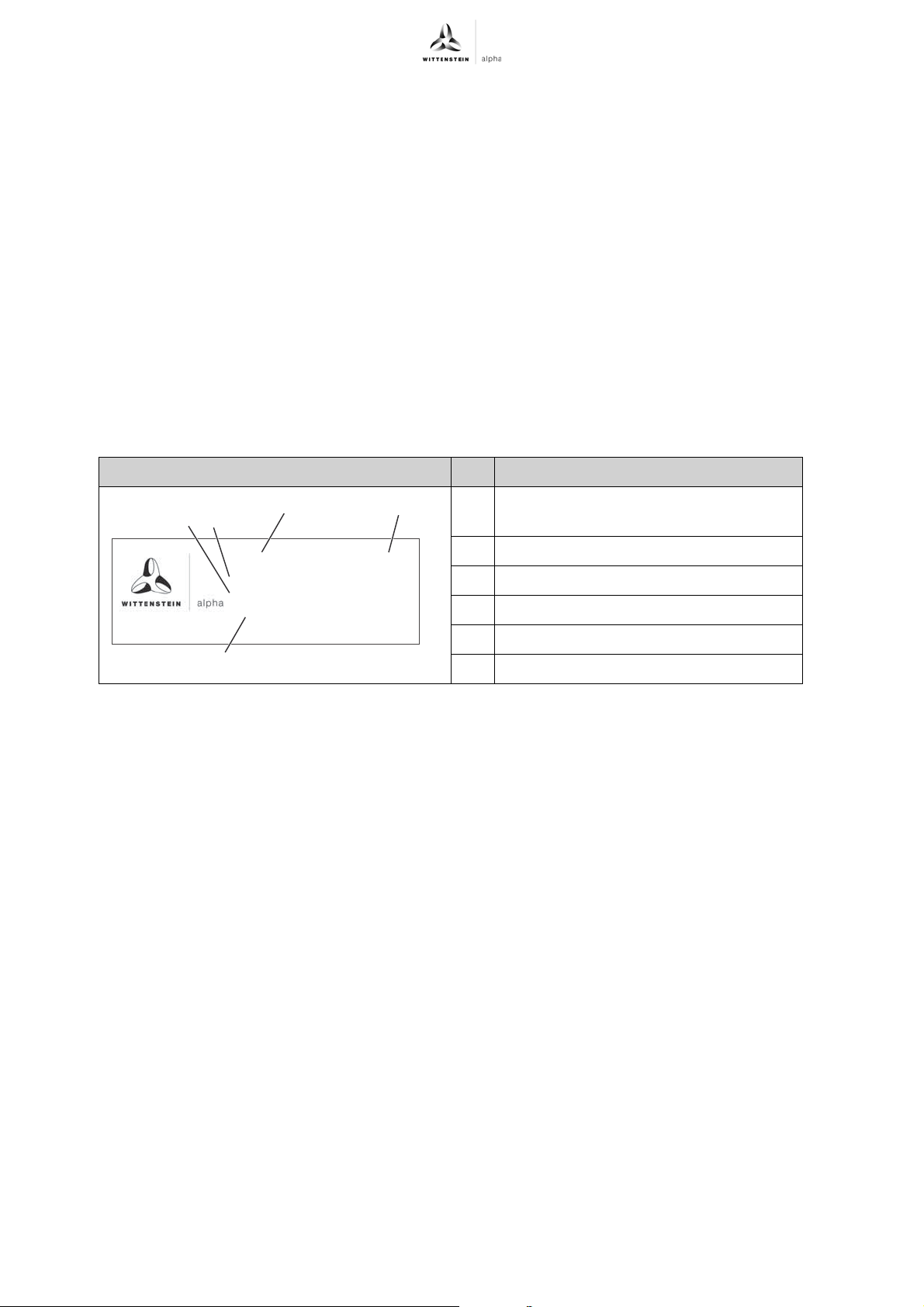
Hot gearhead housing can cause serious burns.
Touch the gearhead housing only when wearing protective gloves or
after the gearhead has been at standstill for some time.
Solvents and lubricants can cause skin irritations.
Avoid direct skin contact.
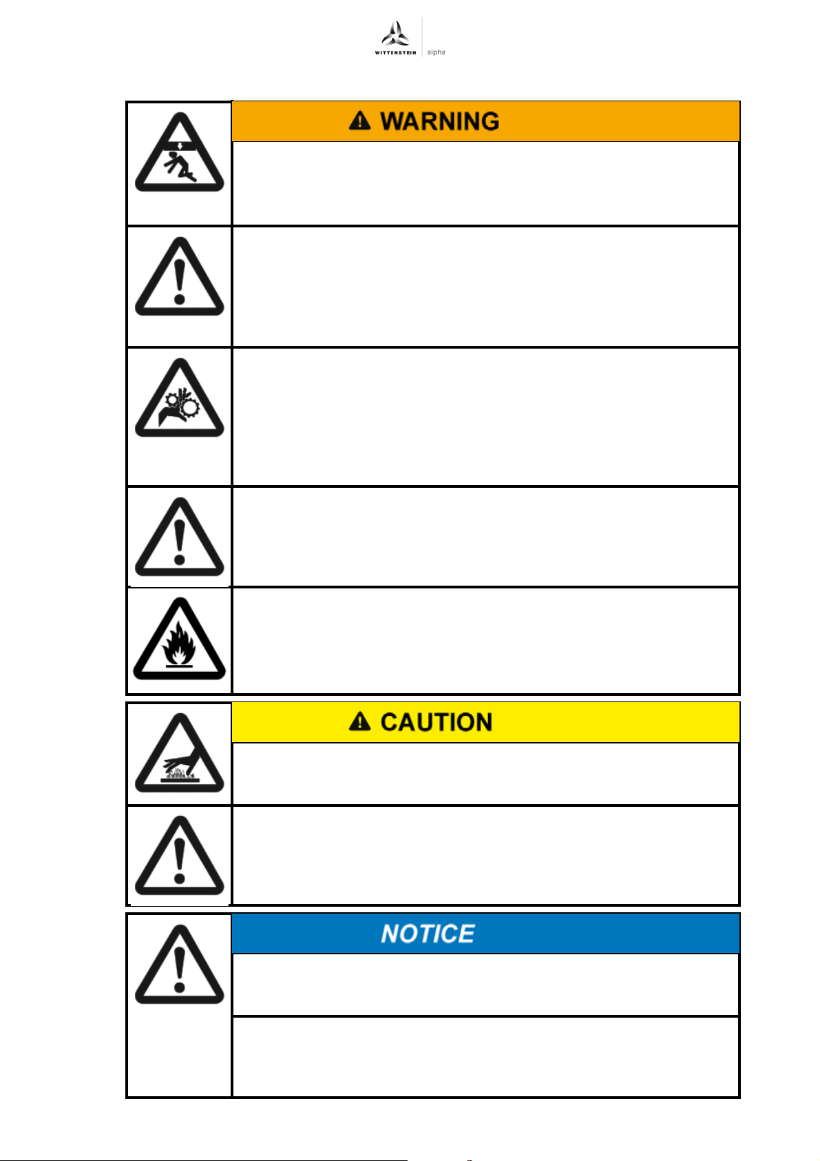
Loose or overloaded screw connections can damage the gearhead.
Use a calibrated torque wrench to tighten and check all screw
connections for which a tightening torque has been specified.
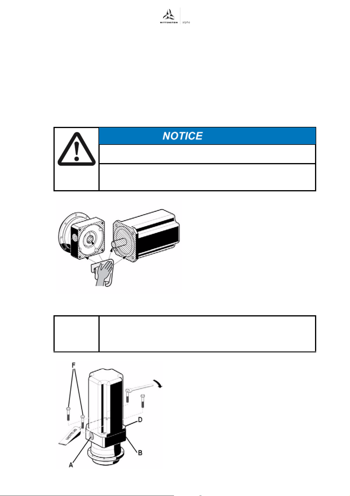
All gearheads are permanently lubricated by the manufacturer with
synthetic gear oil (polyglycols) or with a grease (see identification
plate).
Do not mix polyglycols with mineral oils.