WOBIT ADT42 User manual

PPH WOBIT E.K.J OBER. s.c.
62-045 Pniewy, Dęborzyce 16
tel.(061) 22 27 422, fax.(061) 22 27 439
www.wobit.com.pl
ADT42 User Manual
4-channel measuring module for force sensors
with 0-10V/4-20mA output, USB and RS485 MODBUS

www.wobit.com.pl
User manual -ADT42 –23.06.2015 –v.1.3
page 2
Contains
1. Safety and assembly rules .................................................................................................... 3
1.1. Safety rules.............................................................................................................................. 3
1.2. Assembly recommendation..................................................................................................... 3
2. Device description................................................................................................................ 4
2.1 Intended use and properties................................................................................................... 4
2.2 Features................................................................................................................................... 5
2.3 Description of connectors and diodes..................................................................................... 5
2.4 Power supply ........................................................................................................................... 6
2.5 Force sensors connection........................................................................................................ 6
2.6 Insulated inputs....................................................................................................................... 7
2.7 Transistor outputs ................................................................................................................... 7
2.8 Analog output 0-10V/4-20mA................................................................................................. 7
3. Transducer configuration...................................................................................................... 8
3.1 Connection by USB .................................................................................................................. 8
3.2 Configuration of strain gauge inputs and measurements....................................................... 8
3.2.1 Example of configuration ................................................................................................ 9
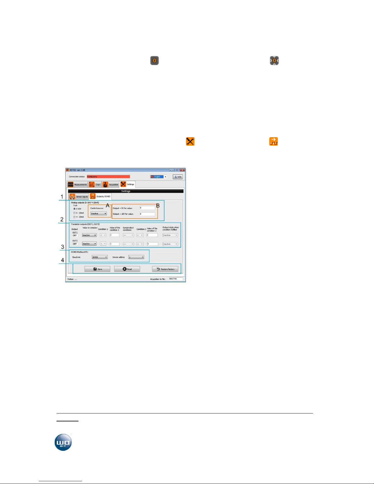
3.3 Configuration of output and RS485....................................................................................... 10
3.3.1 Configuration of analog output..................................................................................... 10
3.3.2 Configuration of transistor outputs............................................................................... 11
3.3.3 Configuration of RS485 MODBUS.................................................................................. 11
4. RS485 MODBUS Communication......................................................................................... 12
5. Complementary information .............................................................................................. 14
5.1 Force sensor types................................................................................................................. 14
5.2 Sensor measuring range........................................................................................................ 14
6. Technical parameters ......................................................................................................... 15
Thank you for selecting our product!
This instruction will help you at correct service and accurate exploitation of described device.
Information included in this instruction were prepared with high attention by our specialists and is description of the
product. Based on the information should not be inferred a certain features or suitability for a particular application. This
information does not release the user from the obligation of own judgment and verification. P.P.H. WObit E.K.J. Ober s.c.
reserves the right to make changes without prior notice.
Please read instructions below carefully and adhere to its recommendation
Please pay special attention to the following characters:
CAUTION!
Not adhere to instruction can cause damage or impede the use of hardware or software.

www.wobit.com.pl
User manual -ADT42 –23.06.2015 –v.1.3
page 3
1.Safety and assembly rules
1.1. Safety rules
•Prior to first start-up of the device carefully read the manual.
•Prior to first start-up of the device make sure all cables are properly connected.
•Provide appropriate working conditions, in compliance with the device
specifications (e.g.: power supply voltage, temperature, maximum current
consumption).
•Prior to any modifications of cables connections, disconnect power supply voltage.
Usage of described device in special meaning systems (e.g.: medical applications, vehicles,
etc.) requires use of additional safety measures against operational errors.
This device can’t be used in open space. It can cause an electric shock and shorten lifetime of
the device.
•Exceeding of recommended operational parameters can lead to damage of the device or to
fire.
Dismantling of the indicator housing during guarantee agreement period results in its
invalidation.
1.2. Assembly recommendation
In the environments of unknown levels of interruptions it is recommended to use the following
means preventing against possible interruptions of the device operation:
Ground or zero the metal rails on which instruments are mounted,
•Do not power the device from the same lines as high power devices without appropriate
network filters.
•Apply power supply, sensor and signal cables screening while screen grounding should be
connected only on one side as close to the device as possible.
For power supply of the motor please use twister pair of cables, if possible equipped with
filters in the form of ferrite beads.
•Avoid routing control (signal) cables in parallel with or in close vicinity of power and supply
cables.
•Avoid close vicinity of devices generating high level of electromagnetic and/or pulse
interference (high power loads, loads with phase or group power regulation).

www.wobit.com.pl
User manual -ADT42 –23.06.2015 –v.1.3
page 4
2.Device description
2.1 Intended use and properties
ADT42 is a multipurpose 4-channel measuring module for load cells. It enables very precise
measurement with resolution up to 100.000 of measuring range.
ADT42 has multipurpose usage as well at industry as in laboratory, where averaged or precise force
(weight) measurement is necessary. Depends on used sensor there is a possibility of measurement of
small masses in range as well small weights (grams) as large loads (tons). Due to possibility of
aggregate of measurements from selected channels the module can be used in multi-sensor weight
systems.
ADT42 has 2 transistor outputs, and 2 insulated inputs (one tare input). Built-in operating modes
enable the device to be used for dosing without any additional controllers. Measured values can be
converted into analogue signal in 0-10V (ADT42-U version) or (0)4-20mA standard (ADT42-I version).
Access to device is also possible through RS485 bus in MODBUS-RTU protocol, which allows direct
communication one or several modules simultaneously with PLC drivers or HMI panels.
Device configuration can be made also by USB connector ADT42-PC program. This program except
device settings enables preview of current measurement values, saving them to a file and to show
data on a graph.

www.wobit.com.pl
User manual -ADT42 –23.06.2015 –v.1.3
page 5
Example of application with ADT42 module (silo weight measurement, weight platform)
2.2 Features
Signal measurement from four load cells
Result conversion into force in N or weight in g, kg, T, f
Read out of each channel separately or aggregate of all channels
Measurement filtering function
0-10V (ADT42-U) / (0)4-20mA (ADT42-I) output with calibration function
2 opt insulated inputs (general-purpose and tare)
2 transistor outputs with configurable thresholds
RS485 interface for communication with other devices in MODBUS-RTU protocol
USB connector for transducer configuration and measurement data acquisition
2.3 Description of connectors and diodes
Picture. 1 Connector and panel description
Nr
Description
Analog output 0-10V/ 4-20mA
1
GND
Ground of analog output
2
AOUT
0-10V / 4-20mA output
Opt insulated inputs
3
IN1
Input 1 (TARA)
4
IN2
Input 2 (M-TARA on/off, record)
5
COM
Ground of opt insulated input
RS485 MODBUS-RTU
6
A
Signal +
7
B
Signal -
Transistor output
8
OUT1
Transistor output 1, max. 0,5A
9
OUT2
Transistor output 2, max. 0,5A
10
GND
Ground of outputs
Power supply
11
VDC+
Power supply 12-24 VDC
12
GND
Ground of power supply
Load cells inputs
13, 17, 21, 25
E+
Sensor power supply +
14, 18, 22, 26
S+
Sensor signal +
15, 19, 23, 27
S-
Sensor signal -
16, 20, 24, 28
E-
Sensor power supply -
Signaling diode description
PWR –Module power supply signaling
COM - RS485 / USB communication signaling
TARA - IN1 input state (TARA)
OUT1/2 - ½ output state

www.wobit.com.pl
User manual -ADT42 –23.06.2015 –v.1.3
page 6
2.4 Power supply
ADT42 module can be powered by voltage in range 12 - 24 VDC (max. 36 VDC). Current consumption
is max. 150mA (for connected 4 force sensors). While using transistor outputs you should add current
consumed on this outputs (max. 0,5A / output).
2.5 Force sensors connection
ADT42 module can cooperate with any force sensor which has bridge with resistance bigger than
150Ω. Sensor(s) should connect according to scheme below.
Picture. 2 Connection of force sensors.
CAUTION!
Sensor wires usually have additional shielded braid, which is connected with metal housing of the
sensor. This signal can be connected to supply ground of ADT42, but we don’t recommend to do
that, while sensor is mounted to metal construction, which can be in different potential.
CAUTION!
Do not short-circuit derivation cables of sensor power supply (E+,E-), and also do not short-circuit
E+ output to other derivation, it can cause damage of the device.
Sensor model
Signals
K200, K300, K500,
KB52, KB82, KMB19,
KMB25, KMB31
K701, K801,
K1101, K1506
K1401, K1501,
K1600
KMM20, KMM30, KMM40,
KMM50, KMM60, K1505,
EMS70, EMS150, EMS200
Power supply +
(V+)
Red
Brown
Red
White
Power supply -
(V-)
Black
Yellow
Black
Brown
Signal + (S+)
Green
Green
Brown
Yellow
Signal - (S-)
White
White
Yellow
Green

www.wobit.com.pl
User manual -ADT42 –23.06.2015 –v.1.3
page 7
Tab. 1 Wires color description for sensors from WObit’s offer. CAUTION it is possible, that colors of signals can
change.
2.6 Insulated inputs
ADT42 has two opt insulated inputs. They’re activate after giving a voltage 5..24 VDC (minimum 3 V),
between input and their common terminal COM by at minimum 10 ms. To keep input inactive,
voltage shouldn’t exceed 1 V.
Input
Description
IN1
Tare of aggregate value of measurement. It takes as long time as on input IN1 is high
state.
IN1 = 0 -> tare inactive
IN1 = 1 -> tare active
IN2
Switching between value with tare and value without tare.
IN2 = 0 -> output signal = aggregate signal after tare
IN2 = 1 -> output signal = aggregate signal before tare
Tab. 2 Functions of opt insulated inputs.
Picture. 3 Opt insulated input
2.7 Transistor outputs
ADT42 has two transistor outputs PNP type, each with load up to 0.5 A. Their thresholds and
operations ranges can be freely configured (by ADT42-PC program). For example output can be
configured in that way, that it turns on after exceeding set value or when it will be between two
values.
Picture. 4 Transistor outputs
CAUTION!
Circuit is assure by polymer fuse. Exceeding of admissible current on some of outputs will cause
turn off of both outputs.
2.8 Analog output 0-10V/4-20mA
Analog output can be configured for converting of measured force (weight) into voltage in range 0 -
10 V (for ADT42-U version) or current 0(4) –20 mA (for ADT42-I version).

www.wobit.com.pl
User manual -ADT42 –23.06.2015 –v.1.3
page 8
3.Transducer configuration
3.1 Connection by USB
USB connector is used for communication with ADT42-PC program which is used for device
configuration and measurement data acquisition. After connecting to PC and starting ADT42-PC
program there should appear information about connection with ADT42. Installation of USB port
drivers isn’t required.
CAUTION
1) USB connection should be established always before turning on of driver power
supply.
2) Connection through USB is susceptible to interferences in supply network and to
electromagnetic interferences, which occurs in industry conditions. While occurring
problems with communication the module with ADT42-PC program, you should use
additional protection elements like:
Power line filter before feeder, which supplies the module,
Good quality USB cable with length < 1,5 m, equipped with ferrite beads,
Opt insulated USB HUBs on PC side.
In some conditions can occur, that communication won’t be possible or measurement data
acquisition won’t be correct.
3.2 Configuration of strain gauge inputs and measurements
After activation of ADT42-PC application you should open Settings tab, and then to Sensor
inputs tab.
1) It allows to define number of active inputs. For
example at operations with two force sensors you
should choose 1 + 2. Values from selected channel are
available as independent measurements and as their
aggregate. Results are presented in „Measurements”
tab.
2) Filtration options allows to decrease or to eliminate
fluctuations to achieve the highest measurement
stability.
3) Parameter settings of force sensors: bridge constant
[mV/V] and bridge range [N]. It allows also zeroing of
selected channel.
4) It cause zeroing of total measured value. It is
equivalent with giving signal on IN1(TARA) input.
5) Options of measurement units and displaying

www.wobit.com.pl
User manual -ADT42 –23.06.2015 –v.1.3
page 9
precision of measurement values (number of
decimals).
6) Reading and recording of introduced parameters to
module, factory settings recall.
Input configuration for force sensors boils down to determine number of used channels (1) and
setting of parameters used for force sensors (3).
Parameters setting of connected force sensors
For force sensor should be introduced parameters as below:
Sensor range [N] –rated load of used sensor in N, usually present on sensor’s housing.
Bridge constant [mV/V] –sensitivity of used sensor in mV/V, usually present on sensor’s housing or
in its documentation. As a rule it is value from a range 1…2 mV/V.
Additionally for each input channel you can reverse measured signal (change sign from + for -) using
option „Reverse the sign” and zeroing channel by pressing „Zero” .
Filtration of measurement
ADT42 has constant averaging filter set in range 0…99 samples and measurement mode „Fast” and
„Slow” (2).
Bigger value of filtration increases stability of measurements, but also causes slower response for
change of signals from sensor. Additionally setting of „slow”mode decreases measurement
frequency 8 times, but it improve its stability.
Picture. 5 Filtration influence on value of measurement.
Units of measurements
Units of measurements (5) determines in which units the module will present measurements (N –
Newton’s, g- gram, kg –kilogram, T –ton, F- pound). Also values available by MODBUS interface are
stored in set units. „Precision” tab set quantity of decimals indicated values in ADT42-PC program
and doesn’t influence on real accuracy of measurement.
3.2.1 Example of configuration
Example: Two force sensors 1,5mV/V, with measuring range up to 500N.
1) Setting of active inputs on „1 + 2”(1)

www.wobit.com.pl
User manual -ADT42 –23.06.2015 –v.1.3
page 10
2) Introducing value 500 (3) in „Rated capacity”window for sensors 1 and 2
3) Introducing value 1,5 (3) in „Rated output” window for sensors 1 and 2
4) Zeroing of sensor’s offset –button for each channel independently or for all channel
simultaneously(3)
5) Saving of settings to device –„Save” button (6)
For multivariant measurements we recommend to set filtration on „Slow” and select filtration level
to achieve compromise between measurement stability and response time on change of force. (2).
Each value change should be saved by „Save”button (6)
3.3 Configuration of output and RS485
After starting ADT42-PC application go to Settings tab, then to Outputs, RS485 tab.
1) Setting of analog output. A –selection of signal
source, sent on 0-10V/4-20mA output, B –
calibration of analog output
2) Setting of transistor outputs OUT 1 and OUT2.
3) Setting of communication parameters RS485
MODBUS
4) Reading and saving set parameters to module
and factory settings recall
3.3.1 Configuration of analog output
This options allows to determine:
Output type: 0-10V, 0-20mA or 4-20mA
Controlling value (A), which will be transferred to analog output. As controlling value you
can select one of 4 channels or aggregate of active channels.
Calibration of input value (B) in relation to controlling signal.
Depend on module version it will be allowable proper analog output:
ADT42-U –module with voltage output –allowable selection 0-10V
ADT42-I –module with current output –allowable selection 0-10mA or 4-20mA
Example 1: For aggregate value in range of 0-2000 analog output can change in range from 4mA up
to 20mA
1) Setting of output mode for 4-20mA

www.wobit.com.pl
User manual -ADT42 –23.06.2015 –v.1.3
page 11
2) Selection of Sum controlling value
3) Setting Output = 4mA for value: 0
4) Setting Output = 20mA for value: 2000
5) Save settings by Save button
Example 2: For value of channel 1 in range from 0 to 500 analog output should change in range from
10V up to 0V
1) Set output mode on 0-10V
2) Selection of Input 1 controlling value
3) Set Output = 0V for value: 500
4) Set Output = 10V for value: 0
5) Save settings by Save button
3.3.2 Configuration of transistor outputs
By using this option it is possible to configure conditions of activation/ deactivation transistor
outputs OUT1 and OUT2.
Example : OUT1 output should be activated when value on 2 input will exceed 500
Example: OUT1 output should be activated in range of measured aggregate value 100 up to 200.
3.3.3 Configuration of RS485 MODBUS
This options allows to set MODBUS baudrate in range: 9600, 19200, 38400, 5760, 115200 and set
slave address in range 1-247.

www.wobit.com.pl
User manual -ADT42 –23.06.2015 –v.1.3
page 12
4.RS485 MODBUS Communication
RS485 can be used for communication with PLC driver, HMI panel or other device operating in
MODBUS-RTU protocol. RS485 port in ADT42 has no galvanic insulation, so you must provide the
same ground potential for ADT42 as for master device.
Default transmission parameters:
Baudrate: 38400bps, bits: 8, Stop bit: 1, Parity: none
Address Modbus: 1
Baudrate and slave address of ADT42 can be changes by ADT42-PC program.
Used MODBUS functions
Function number (hex)
Description
1 (0x01)
Reading of output state (OUT1, OUT2)
2 (0x02)
Reading of input state (IN1, IN1)
3 (0x03)
Reading of X registers
5 (0x05)
Record of single bit
Plan of ADT42 registers
Address
Name
Type of
variable
Mode(Modbus
function)
Description
Values stored in registers INT type (integral number)
0 (*1)
SUM_INT
INT
R (0x03)
Aggregate value of measurement
2 (*3)
SUM_MIN_INT
INT
R (0x03)
Recorded minimal value
2 (*3)
SUM_MAX_INT
INT
R (0x03)
Recorded maximal value
3 (*4)
CANAL0_INT
INT
R (0x03)
Value of 1 channel
4 (*5)
CANAL1_INT
INT
R (0x03)
Value of 2 channel
5 (*6)
CANAL2_INT
INT
R (0x03)
Value of 3 channel
6 (*7)
CANAL3_INT
INT
R (0x03)
Value of 4 channel
7 (*8)
ANALOG_INT
INT
R (0x03)
Value of analog output (x1000)
Values stored in registers REAL type (floating point number)
8 -9 (*9-10)
SUM_REAL
REAL
R (0x03)
Aggregate value of measurement
10 -11 (*11-12)
SUM_MIN_REAL
REAL
R (0x03)
Recorded minimal value
12 -13 (*13-14)
SUM_MAX_REAL
REAL
R (0x03)
Recorded maximal value
14 -15 (*15-16)
CANAL0_REAL
REAL
R (0x03)
Value of 1 channel
16 -17 (*17-18)
CANAL1_REAL
REAL
R (0x03)
Value of 2 channel
18 -19 (*19-20)
CANAL2_REAL
REAL
R (0x03)
Value of 3 channel
20 -21 (*21-22)
CANAL3_REAL
REAL
R (0x03)
Value of 4 channel
22 -23 (*23-24)
ANALOG_REAL
REAL
R (0x03)
Value of analog output
1 –bit values
4000 (*4001)
MIN_MAX_RESET
BIT
W (0x05)
Zeroing of min/max. value
4001 (*4002)
TARA
BIT
W (0x05)
Tare of aggregate value
4002 (*4003)
ZERO_CANAL1
BIT
W (0x05)
Zeroing of 1 channel
4003 (*4004)
ZERO_CANAL2
BIT
W (0x05)
Zeroing of 2 channel
4004 (*4005)
ZERO_CANAL3
BIT
W (0x05)
Zeroing of 3 channel
4005 (*4006)
ZERO_CANAL4
BIT
W (0x05)
Zeroing of 4 channel
4006 (*4007)
ZERO_ALL
BIT
W (0x05)
Zeroing of 1..4 channels
5000 (*5001)
INPUTS
BIT
R(0x02)
Reading of inputs state
bit 0 –IN1
bit 1 –IN2
6000 (*6001)
OUTPUTS
BIT
R(0x01)
Reading/ output setting

www.wobit.com.pl
User manual -ADT42 –23.06.2015 –v.1.3
page 13
6000 (*6002)
6001 (*6003)
OUT1
OUT2
W(0x05)
bit 0 –OUT1
bit 1 –OUT2
*for addresses beginning from 1 (offset of address +1)
R –register reading, W - record
CAUTION: 4-byte number REAL type is contained in two registers. The first registry contains younger part of the number,
the second - its older part. In order to read REAL number value correctly, read two registers (X, X+1), and then conduct
appropriate conversion.
Conversion of 2 registries (4 Byte) into 32 Bit number REAL
Register _X HI
Register _X LO
Register _X+1 HI
Register _X+1 LO
<-> Byte1
<-> Byte0
<-> Byte3
<-> Byte2
Number_32_bit = Byte3<<24 + Byte2<<16 + Byte1<<8 + Byte0, or Number_32_bit = Register_2 + Register_3<<16
Example of MODBUS communication table
Reading of measurements from SUM_IREAL register (Function: 03, Register address: 0)
Request (MODBUS MASTER -> ADT42)
Response (ADT42-> MODBUS MASTER)
Device address
0x01
Device address
0x01
Function
0x03
Function
0x03
Hi registry address
0x00
Number of bytes
0x04
Lo registry address
0x00
Register 0x02 Hi
REAL (Byte 1)
Number of Hi registries
0x00
Register 0x02 Lo
REAL (Byte 0)
Number of Lo registries
0x02
Register 0x03 Hi
REAL (Byte 3)
CRC Hi
0xC4
Register 0x03 Lo
REAL (Byte 2)
CRC Lo
0x0B
CRC Hi
8 bit
CRC Lo
8 bit
Tare –bit setting of TARA register (Function: 05, Register address: 4001)
Request (MODBUS MASTER -> ADT42)
Response (ADT42) -> MODBUS MASTER)
Device address
0x01
Device address
0x01
Function
0x05
Function
0x05
Hi registry address
0x0F
Hi register address
0x0F
Lo registry address
0xA1
Lo register address
0xA1
Register 0x00 Hi
0xFF
Register 0x00 Hi
0xFF
Register 0x00 Lo
0x00
Register 0x00 Lo
0x00
CRC
16 bit
CRC
16 bit

www.wobit.com.pl
User manual -ADT42 –23.06.2015 –v.1.3
page 14
5.Complementary information
5.1 Force sensor types
WObit company has a broad offer of force sensors in range from single Newton’s up to hundreds of
kilo Newton’s. Depends on assembly and way of measuring force (tension, compression) are
available sensors with different shapes (table below).
Beam
To measure tension force. Range of measured force 0..350 N.
Example of models: K200, K300
S-beam
To measure large tension force. Range of measured force 0..75 kN.
Example of models: K1401, K1501, K1505, K1506, K1600
Round
To measure large and small tension force. Range of measured
force 0..100 kN.
Example of models: KB52, KB82, KMB19, KMB25, KMB31, KMM30,
KMM50, KMM60,
Round with
shaft
To measure large and small tension and compression force. Range
of measured force 0..50 kN.
Example of models: KMM20, KMM40
Cylindrical
To measure large tension and compression force. Range of
measured force 0..200 kN.
Example of models: K1101
5.2 Sensor measuring range
Rated load for sensor it is a size of force, which specifies
top value of measuring range (given value for sensor as
bridge range -TRA in N).
Applied load is the biggest force, which have
unambiguous connection between force and output
signal (signal value is changing linear in relation to force).
It can count max. M150% of sensor range (bridge).
Cut-off load is the biggest force, which can take each
sensor without it damage. It can count max. 200% of
sensor range.
Destroying load means force applied to sensor Shaft,
which exceeding can cause to mechanical damage of the
sensor.
Constant of e.g. KMM60 sensor is 1,5mV/V 2%. Error of the sensor is specified by following values:
tolerance of linearity 0,2% of measuring range, zero tolerance 2% of measuring range, hysteresis
0,2% of range and creep measured in time of 30 minutes 0,1%. Temperature factor of zero point
Destroying load
>200% F
Cut-off load
+200% F
Applied load
+150% F
Rated load
+100% F
Measuring range
Zero load
0 [N]
Rated load
-100% F
Applied load
-150% F
Cut-off load
-200% F
Destroying load
<200% F

www.wobit.com.pl
User manual -ADT42 –23.06.2015 –v.1.3
page 15
and constant is 0,1% of range/10oC. Bridge resistance on input has 380om ±10% and output
resistance has 350om ±5%.
6.Technical parameters
Mechanical parameters
Housing dimensions:
120 x 101 x 23 mm
Weight:
100 g
Operating temperature
range:
5..50°C
Protection class:
IP20,
Mounting
Handle on DIN rail
Electrical parameters
Power supply
12…24 VDC, 150 mA + OUT1, OUT2 outputs current
Force sensor inputs
Sensor power supply: 5 V (also 10V sensors)
Max. differential voltage: ±39mV,
Resolution: 0,001% FS (for typical bridge with sensitivity
2mV/V) Temperature error: 0,0025%/C°
Measurement frequency (filtration mode: slow/fast)
1 active channel: 10 Hz / 80 Hz
2 active channel: 1,2 Hz / 10 Hz
3 active channel: 0,8 Hz / 6,5 Hz
4 active channel: 0,6 Hz / 5 Hz
Time of initial annealing: about 10 min
Digital inputs IN1, IN2
Opt insulated,
Low state: 0 V (max. 1 V), high state: +24 V (5…24 V)
Min. pulse length >10 ms,
Transistor inputs OUT1, OUT1
Transistor OC , PNP type
Max. ampacity: 0,5 A
Low state: OUT = 0 V
High state: OUT = VDC (voltage supply of the module)
Analog output 0-10 V
( ADT42-U version)
0-10 V mode : V min = 0,015 V, V max = 10V, max. load 20 mA
Resolution : ±3 mV, Accuracy 10 mV (0,1% FS)
Analog output 0/4-20 mA
(ADT42-I version)
(0)4-20 mA mode: I min = 0,1 mA, I max = 24 mA
Resolution: ±13µA, Accuracy 0,05 mA (0,25% FS)
Communication
RS485 MODBUS-RTU, (by default: 38400bps, 8:n:1, address: 1)
USB: 1.1, 2.0
Table of contents