5
INSTALLATION INSTRUCTIONS
IMPORTANT NOTE:
When multiple cooktops
and/or modules are installed side by side, refer
to countertop cut-out dimensions on page 9.
Wolf induction cooktops can accommodate a
Wolf downdraft ventilation system. Refer to
installation instructions provided with the
downdraft for additional specifications.
UNFRAMED INDUCTION COOKTOPS
IMPORTANT NOTE:
A minimum height clear-
ance of 61/2" (165) is required between the
countertop and any combustible surface
directly below the cooktop. This includes upper
edges of drawers located directly below unit. If
a shelf is installed below the unit, a 1" (25) gap
at the rear of the cabinet shelf is necessary to
allow for proper ventilation. Failure to do so
could result in decreased performance or
product damage.
IMPORTANT NOTE:
Unframed induction
cooktops are not designed to be installed in
combination with other cooktops.
IMPORTANT NOTE:
Unframed induction
cooktops cannot be installed with a downdraft
ventilation system.
For installation options of the unframed induc-
tion cooktops, refer to Unframed Installation
on pages 12–13.
Dimensions in parentheses are in
millimeters unless otherwise specified.
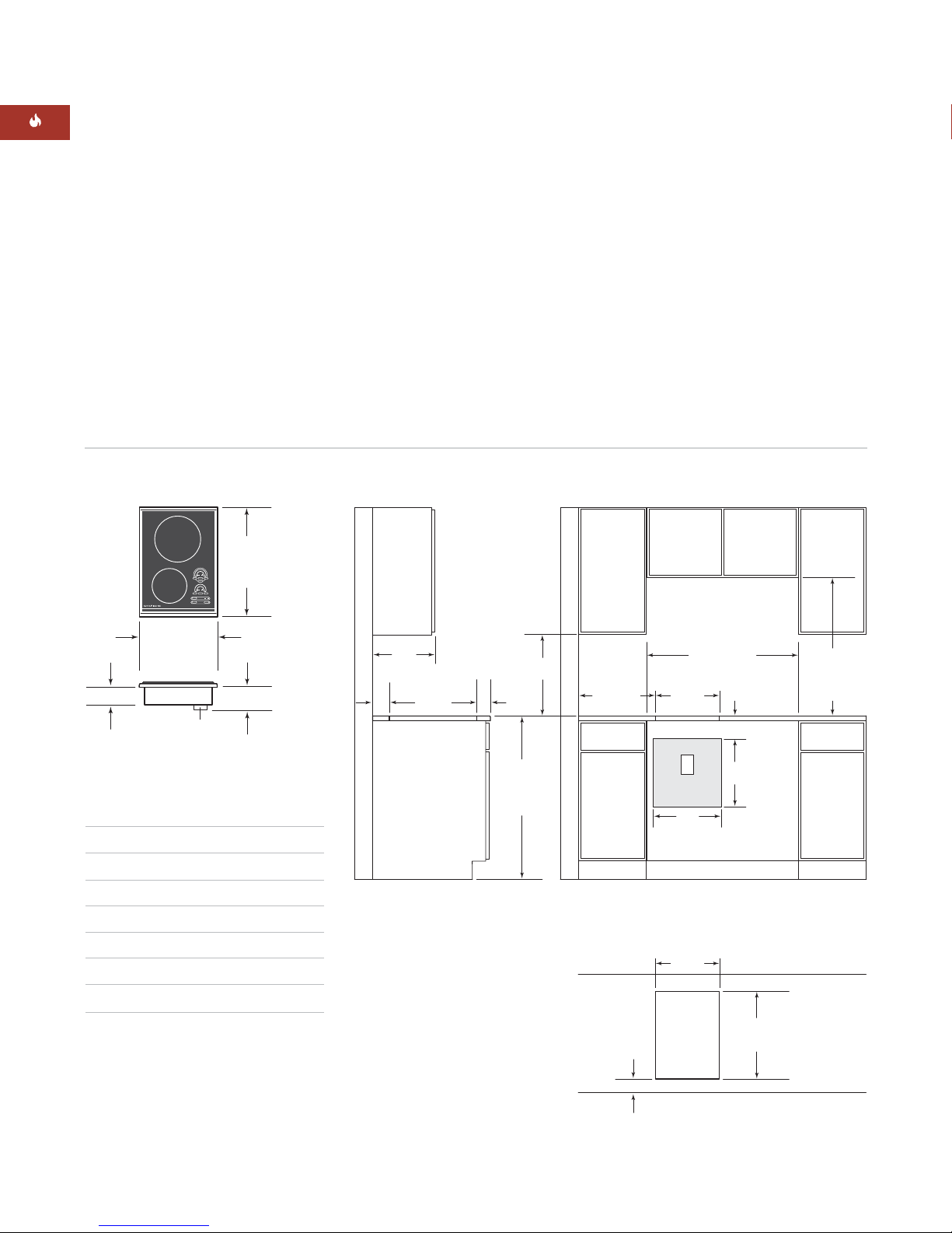
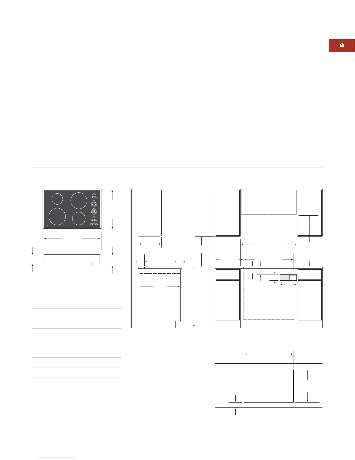
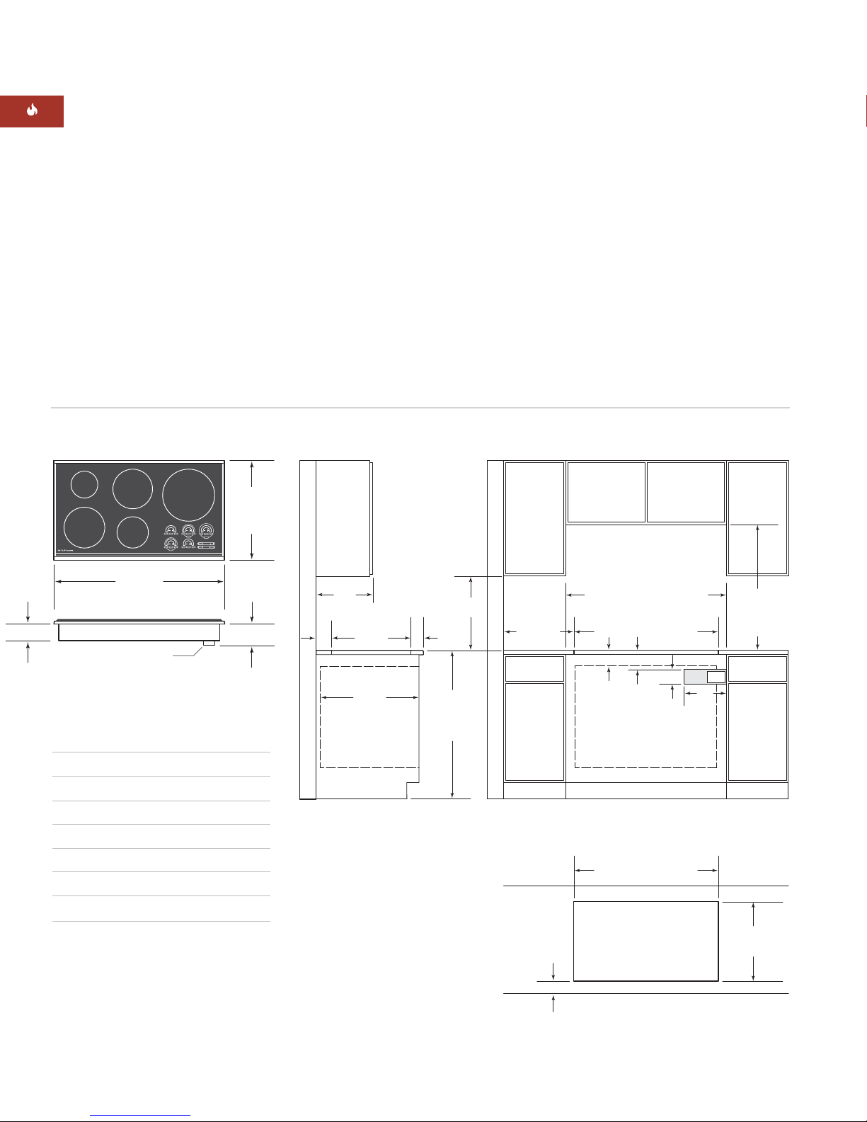
INSTALLATION SPECIFICATIONS
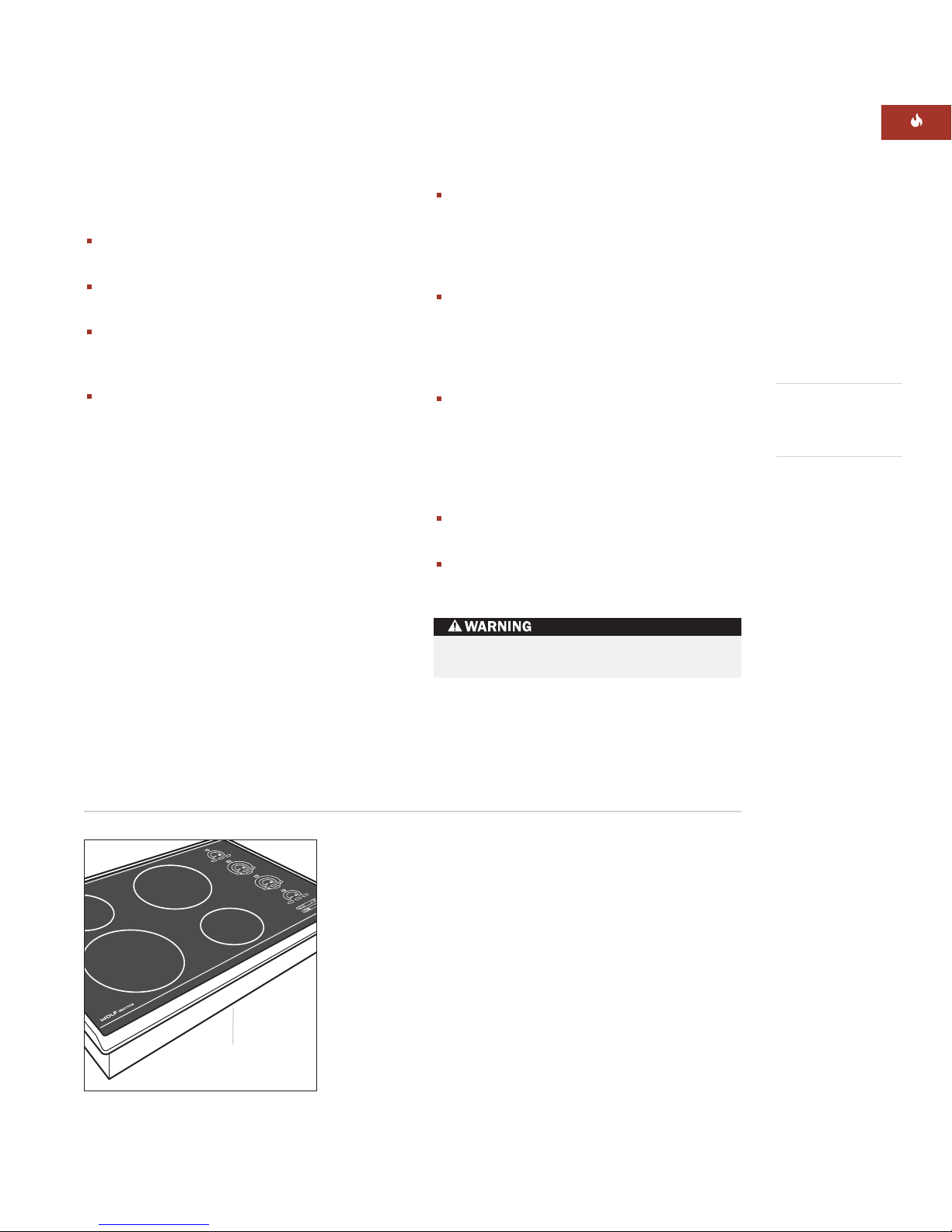
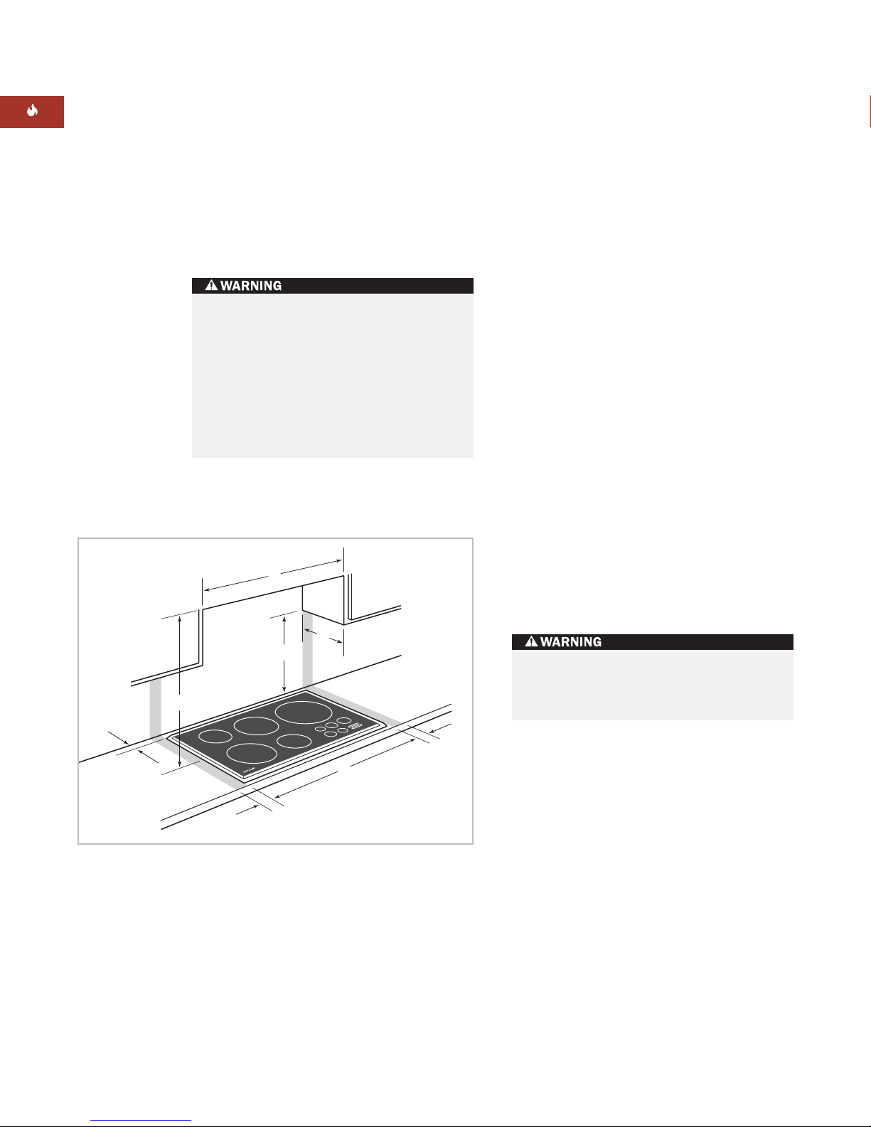
The illustrations on pages 6–11 provide the
overall dimensions, installation specifications
and countertop cut-out for each of the Wolf
induction cooktop models.
These cooktops are designed to fit a standard
24" (610) deep base cabinet with a 25" (635)
deep countertop. Before making the counter-
top cut-out, verify that the cooktop will clear
the side walls of the base cabinet below.
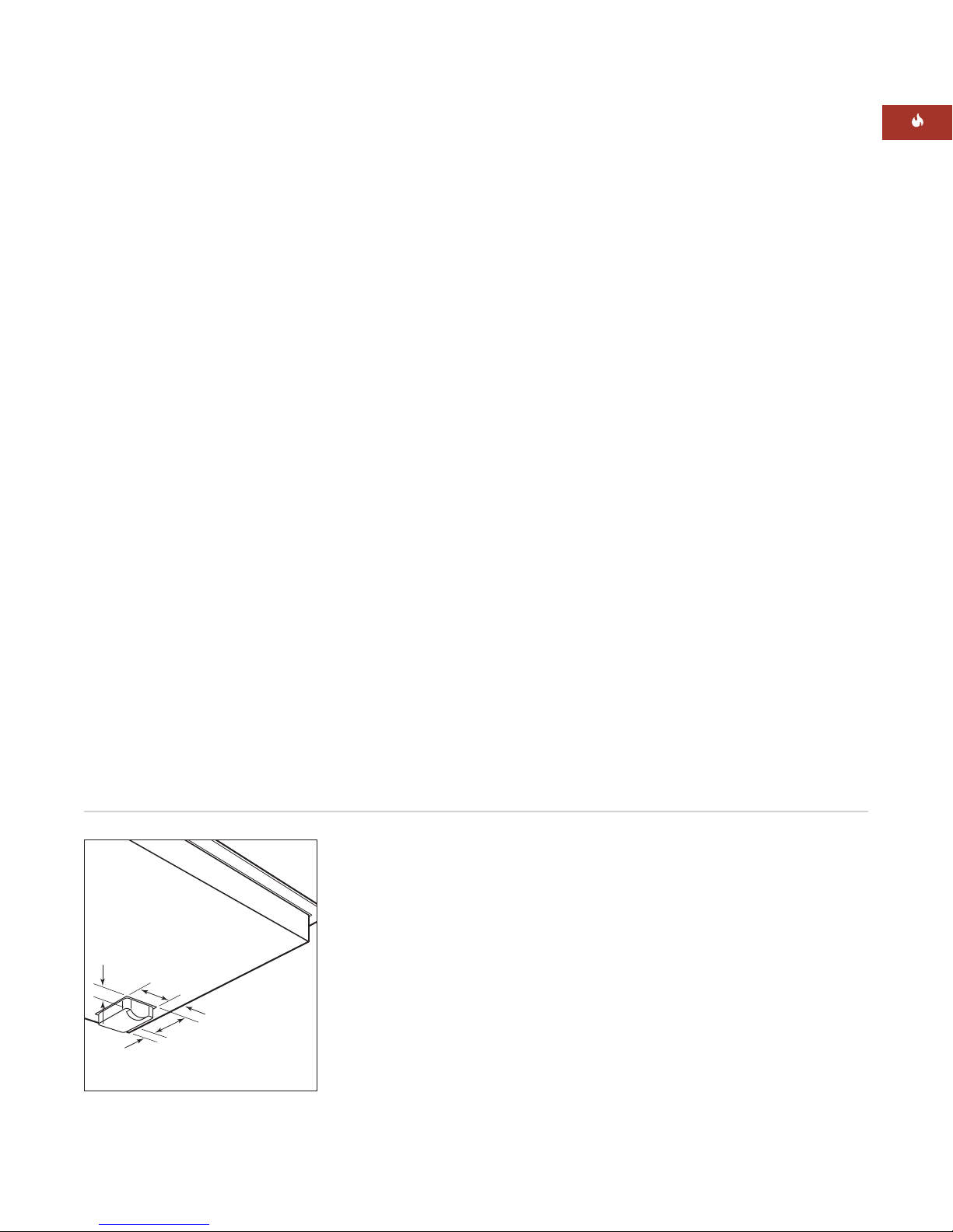
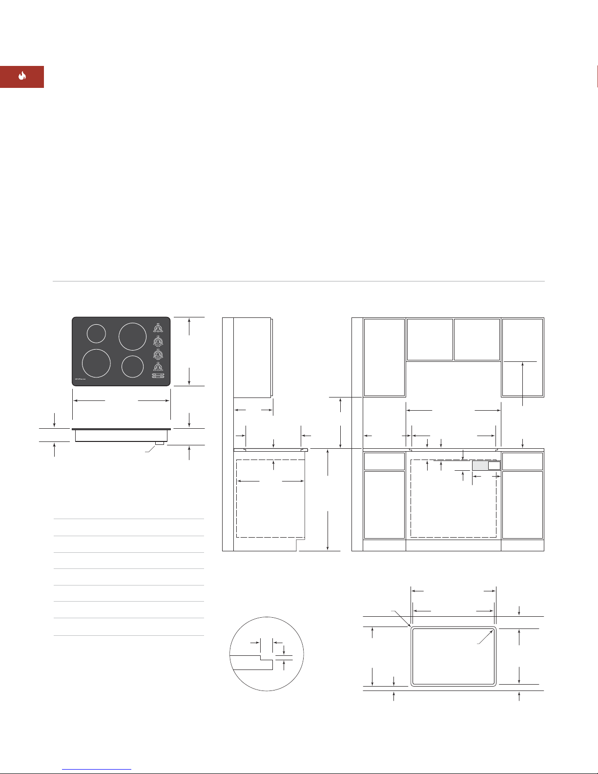
Clearance is required for the terminal block
located at the right rear of the cooktop. Refer
to the illustration below for dimensions.
FRAMED INDUCTION COOKTOPS
IMPORTANT NOTE:
A minimum height clear-
ance of 6" (152) is required between the coun-
tertop and any combustible surface directly
below the cooktop. This includes upper edges
of drawers located directly below unit. If a
shelf is installed below the unit, a 1" (25) gap
at the rear of the cabinet shelf is necessary to
allow for proper ventilation. Failure to do so
could result in decreased performance or
product damage.
Wolf induction cooktops are designed to be
installed in combination with other cooktop
units.
35/16"
(84)
23/16"
(56)
15/16"
(24)
7/8"
(22)
11/4" (32)
Terminal block dimensions