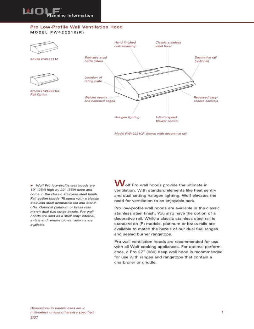
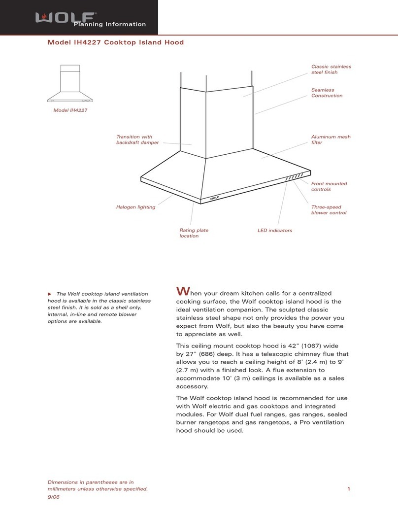
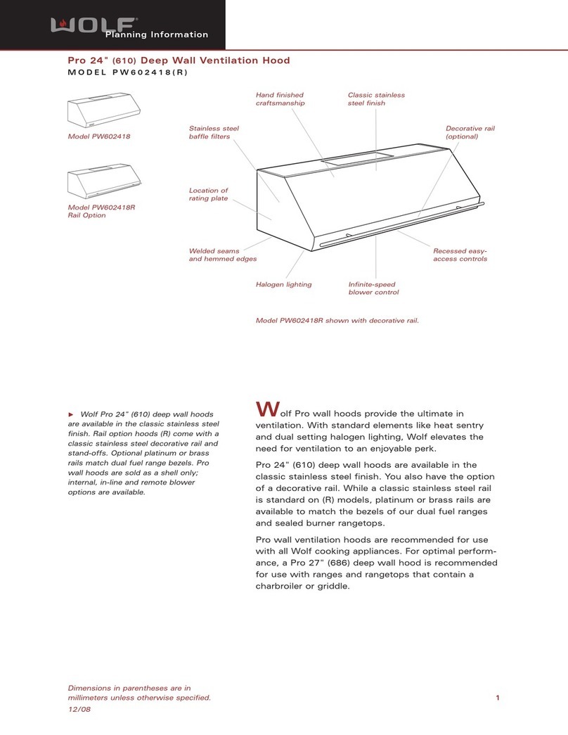
Wolf VC48W User manual

SERVICE MANUAL INTRODUCTION
This service manual helps with troubleshooting and diagnosing
malfunctions, completion of repairs, and return of the product to
proper operating condition. Read the complete instructions
contained within before initiating any repairs.
This guide is intended for use by Factory Certified Service. Wolf
Appliance, Inc. recommends that only Factory Certified Service
companies do repairs.
Warning and Caution product safety labels appear throughout
this manual. Product safety labels appear at the beginning of
some sections. Follow the instructions in the product safety
labels to avoid personal injury and/or product damage. The
sample safety labels explain the types of notices that appear in
this manual.
WARNING
States a hazard that may cause serious injury or
death if precautions are not followed.
CAUTION
Indicates minor injury or product damage may occur
if precautions are not followed.
IMPORTANT NOTE: Highlights especially important information.
TIP: Indicates additional, useful information.
Information and images contained herein are copyright of Wolf
Appliance, Inc. Neither this manual nor any information or
images contained herein may be copied or used in whole or in
part without the express written consent of Wolf Appliance, Inc.
©Wolf Appliance, Inc., all rights reserved.
WOLF PRODUCT RATING PLATE INFORMATION
On Ceiling-Mounted Hoods, the rating plate is found behind the
rightmost filter. Open the center panel, and remove the filter.
Product
Rating
Plate
Important information for each product is listed on the product
rating plate. Rating plates identify:
▪Model
▪Serial number
▪Electrical information
MODEL DESCRIPTIONS AND SALES ACCESSORIES
For more details on individual model descriptions and a listing
of all compatible sales accessories, see the
Wolf Product and
Sales Accessory Reference Guide
.
V SERIES VENTILATION MODEL KEY
Model Character Description
ICB International Designation
V V Series Ventilation
C Model Type Ceiling
I Model Type Island
U Model Type Under-Cabinet
W Model Type Wall
24, 30, 36 or 48 Width (in inches)
B Exterior: Black
G Exterior: Glass
S Exterior: Stainless Steel
W Exterior: White Glass
PRODUCT USE AND CARE AND INSTALLATION GUIDES
Product use and care guides, installation guides, and other
product specifications are available in the
Product
Specifications and Manuals Library
.
Ceiling-Mounted Hood
General Information
GENERAL INFORMATION
service.subzero.com
828149 REV. A 1
UNIT WARRANTY
Product warranty is determined by the installation location and
the date of installation.
▪View product warranties at
http://service.subzero.com/
ClaimsAndOrderProcessing/Pages/WarrantyInfo
.
▪Warranties start on the day of product installation.
▪Search for warranty and service information by serial
number, customer last name, and address using Unit
History at
http://service.subzero.com/Tools/UnitHistory
.
Ceiling-Mounted Hood
General Information
Unit Warranty (continued)
service.subzero.com
828149 REV. A 2

COMPONENT ACCESS AND REMOVAL
WARNING
To avoid electric shock, disconnect power to the
hood when servicing or working near electrical
components. If removing a hood from its installation,
remember that the units are heavy and lowering them
from the installation may require two persons. Only
an authorized service technician or installer should
remove a unit from its installation.
CAUTION
When working on the hood or its components, be
careful when handling sheet metal parts. The edges
may be sharp.
TURN ON THE REMOTE CONTROL INFRARED SENSOR
1Verify the remote control has new AAA batteries. If not,
replace them.
2Verify the blower and lights are off.
3If the remote does not turn the blower lights on and off,
press and hold on the hood control panel for five seconds.
The LED on the hood flashes twice to indicate that the
remote control infrared sensor is on.
TIP: If the remote control infrared sensor is on, pressing and
holding on the hood control panel for five seconds turns
off the sensor.
FILTER REMOVAL
Remove the Filter
1Push the plastic tab on the front end of the filter toward the
rear of the hood, and pull down.
2Pull the filter forward, and remove it from the unit.
FILTER INSTALLATION
Install the Filter
1Set the filter in the filter opening, back of the filter first.
2Push the plastic tab on the front end of the filter toward the
back of the filter.
3Rotate the filter upward into place, and release the plastic
tab.
INNER PANEL MAGNET REMOVAL
Remove the Inner Panel Magnet
1Use a 3/16" combination wrench underneath the inner panel
magnet bracket to hold the magnet anchor.
2Turn the inner panel magnet counterclockwise to remove it.
INNER PANEL MAGNET INSTALLATION
Ceiling-Mounted Hood
Component Access and Removal
service.subzero.com
828149 REV. A 3

Install the Inner Panel Magnet
1Place the magnet anchor under the inner panel magnet
bracket.
2Use a 3/16" combination wrench to hold the magnet anchor
from underneath.
3Turn the inner panel magnet clockwise to install it.
INNER PANEL ASSEMBLY REMOVAL
Uninstall the Unit
1Turn off the power to the unit.
2Remove the unit from the installation.
TIP: Removing the internal blower first may make uninstalling
the unit easier.
Remove the Inner Panel Assembly
1Pull on the magnet side of the inner panel assembly to open
it and access the inner panel hinges.
2Use a Phillips screwdriver to remove the inner panel hinge
screws.
TIP: Support the inner panel assembly from underneath while
removing the inner panel hinge screws.
3Remove the inner panel assembly from the unit.
INNER PANEL ASSEMBLY INSTALLATION
Install the Inner Panel Assembly
1Place the inner panel assembly over the hinges.
2Use a Phillips screwdriver to install the inner panel hinge
screws.
INNER PANEL HINGE REMOVAL
To remove the inner panel hinge, first remove the inner panel
assembly.
Uninstall the Unit
1Turn off the power to the unit.
2Remove the unit from the installation.
TIP: Removing the internal blower first may make uninstalling
the unit easier.
Remove the Inner Panel Assembly
1Pull on the magnet side of the inner panel assembly to open
it and access the inner panel hinges.
2Use a Phillips screwdriver to remove the inner panel hinge
screws.
TIP: Support the inner panel assembly from underneath while
removing the inner panel hinge screws.
3Remove the inner panel assembly from the unit.
Remove the Inner Panel Hinge
1Use the tip of a Phillips screwdriver to push the hinge pin
out of the inner panel hinge.
2Remove the inner panel hinge leaf from the unit.
3Use a Phillips screwdriver to remove the countersunk
screws that hold the inner panel hinge to the frame.
Ceiling-Mounted Hood
Install the Inner Panel Magnet (continued)
service.subzero.com
828149 REV. A 4

4Remove the frame hinge leaf from the unit.
INNER PANEL HINGE INSTALLATION
Install the Inner Panel Hinge
1Place the frame hinge leaf onto the unit.
2Use a Phillips screwdriver to install the frame hinge leaf
mounting screws to the frame.
3Insert the inner panel hinge leaf into the hinge.
4Insert the hinge pin into the inner panel hinge.
Install the Inner Panel Assembly
1Place the inner panel assembly over the hinges.
2Use a Phillips screwdriver to install the inner panel hinge
screws.
INNER SIDE PANEL REMOVAL (WHITE GLASS)
Remove the Inner Side Panel
1Use a Phillips screwdriver to remove the screws that hold
the inner side panel to the outer panel.
2Rotate the inner side panel inward, so that the tabs come
loose from the frame.
TIP: It may be necessary to close the inner panel to allow
enough clearance for the inner side panel to rotate.
3Remove the inner side panel from the unit.
INNER SIDE PANEL INSTALLATION (WHITE GLASS)
Install the Inner Side Panel
1Place the inner side panel flat against the frame, so that the
tabs align with the slots in the frame.
2Rotate the inner side panel upward into position.
TIP: It may be necessary to close the inner panel to allow
enough clearance for the inner side panel to rotate.
3Use a Phillips screwdriver to install the inner side panel
screws.
OUTER PANEL REMOVAL
To remove the outer panel, first uninstall the unit. Then, remove
the inner side panels.
Uninstall the Unit
1Turn off the power to the unit.
2Remove the unit from the installation.
TIP: Removing the internal blower first may make uninstalling
the unit easier.
Remove the Inner Side Panel
1Use a Phillips screwdriver to remove the screws that hold
the inner side panel to the outer panel.
2Rotate the inner side panel inward, so that the tabs come
loose from the frame.
TIP: It may be necessary to close the inner panel to allow
enough clearance for the inner side panel to rotate.
Ceiling-Mounted Hood
REMOVE THE INNER PANEL HINGE (continued)
service.subzero.com
828149 REV. A 5

3Remove the inner side panel from the unit.
Remove the Outer Panel
1Use a Phillips screwdriver to remove the screws around the
outside of the outer panel.
2Lift the outer panel from the unit.
OUTER PANEL INSTALLATION
Install the Inner Side Panel
1Place the inner side panel flat against the frame, so that the
tabs align with the slots in the frame.
2Rotate the inner side panel upward into position.
TIP: It may be necessary to close the inner panel to allow
enough clearance for the inner side panel to rotate.
3Use a Phillips screwdriver to install the inner side panel
screws.
Install the Outer Panel
1Place the outer panel onto the unit.
2Use a Phillips screwdriver to install the screws around the
outside of the outer panel.
LED LIGHT REMOVAL (STAINLESS STEEL)
Remove the LED Light Assembly
1Use a flat-blade screwdriver to pull the LED light assembly
away from the stainless steel panel.
2Pull the LED light assembly's wire harness far enough
through the hole to access the connector.
3Disconnect the wire harness from the LED light assembly.
4Remove the LED light assembly from the unit.
5Use a Phillips screwdriver to remove the diffuser sleeve
from the LED light.
LED LIGHT INSTALLATION (STAINLESS STEEL)
Install the LED Light Assembly (Stainless Steel)
1Use a Phillips screwdriver to install the diffuser sleeve onto
the LED light.
2Connect the LED light wire harness.
TIP: The other end of the wire harness may be inside the
stainless steel panel on the other side of the hole. Pull it through
far enough to access the connector.
3Place the LED light assembly on the stainless steel panel.
4Push the LED light assembly into the stainless steel panel.
Ceiling-Mounted Hood
REMOVE THE INNER SIDE PANEL (continued)
service.subzero.com
828149 REV. A 6

LED LIGHT ASSEMBLY REMOVAL (WHITE GLASS)
To remove the LED light, first uninstall the unit and remove the
filters, inner side panel, and outer panel.
Uninstall the Unit
1Turn off the power to the unit.
2Remove the unit from the installation.
TIP: Removing the internal blower first may make uninstalling
the unit easier.
Remove the Inner Side Panel
1Use a Phillips screwdriver to remove the screws that hold
the inner side panel to the outer panel.
2Rotate the inner side panel inward, so that the tabs come
loose from the frame.
TIP: It may be necessary to close the inner panel to allow
enough clearance for the inner side panel to rotate.
3Remove the inner side panel from the unit.
Remove the Outer Panel
1Use a Phillips screwdriver to remove the screws around the
outside of the outer panel.
2Lift the outer panel from the unit.
Remove the LED Light Assembly (White Glass)
1Use a Phillips screwdriver to remove the LED light bracket
screws.
2Remove the LED light assembly from the LED light bracket.
3Pull the LED light wire harness far enough through the hole
to access the connector.
4Disconnect the LED light wire harness.
5Remove the LED light from the unit.
LED LIGHT ASSEMBLY INSTALLATION (WHITE GLASS)
Install the LED Light Assembly (White Glass)
1Connect the LED light wire harness.
TIP: The other end of the wire harness may be inside the frame
on the other side of the hole. It can be pulled through far
enough to access the connector.
2Place the LED light assembly on the frame.
3Place the LED light bracket over the LED light assembly.
Ceiling-Mounted Hood
LED Light Assembly Removal (White Glass) (continued)
service.subzero.com
828149 REV. A 7

4Use a Phillips screwdriver to install the LED light bracket
screws.
Install the Outer Panel
1Place the outer panel onto the unit.
2Use a Phillips screwdriver to install the screws around the
outside of the outer panel.
Install the Inner Side Panel
1Place the inner side panel flat against the frame, so that the
tabs align with the slots in the frame.
2Rotate the inner side panel upward into position.
TIP: It may be necessary to close the inner panel to allow
enough clearance for the inner side panel to rotate.
3Use a Phillips screwdriver to install the inner side panel
screws.
CONTROL ASSEMBLY REMOVAL
To remove the control assembly, first remove the filters.
Remove the Filter
1Push the plastic tab on the front end of the filter toward the
rear of the hood, and pull down.
2Pull the filter forward, and remove it from the unit.
Remove the Control Assembly
1Use a Phillips screwdriver to remove the screws holding the
control assembly to the frame.
2Use a flat-blade screwdriver to remove the wire cover on
the rear of the control assembly.
3Disconnect the wire harness from the control assembly.
4Remove the control assembly from the unit.
CONTROL ASSEMBLY INSTALLATION
Install the Control Assembly
1Connect the wire harness to the control assembly.
2Install the wire cover over the rear of the control assembly.
3Place the control assembly into the unit, so that the buttons
go through the holes in the frame.
4Use a Phillips screwdriver to install the screws holding the
control assembly to the frame.
Install the Filter
1Set the filter in the filter opening, back of the filter first.
2Push the plastic tab on the front end of the filter toward the
back of the filter.
3Rotate the filter upward into place, and release the plastic
tab.
POWER BOARD AND TRANSFORMER CASE REMOVAL
To remove the power board and transformer case, first uninstall
the unit and remove the filters.
Uninstall the Unit
1Turn off the power to the unit.
2Remove the unit from the installation.
TIP: Removing the internal blower first may make uninstalling
the unit easier.
Ceiling-Mounted Hood
INSTALL THE LED LIGHT ASSEMBLY (WHITE GLASS) (continued)
service.subzero.com
828149 REV. A 8

Remove the Filter
1Push the plastic tab on the front end of the filter toward the
rear of the hood, and pull down.
2Pull the filter forward, and remove it from the unit.
Remove the Power Board and Transformer Case
1Open the ribbon cable cover of the power board assembly
with a flat-blade screwdriver, and disconnect the wire
harness.
2Use a Phillips screwdriver to remove the screws holding the
power board and transformer case to the unit.
3Use a Phillips screwdriver to remove the screws holding the
power board and transformer case together.
4Inside the power board and transformer case, disconnect
the wire harnesses from the power board.
5Remove the power board from the unit.
Hold-Down
Screws
Case
Screws
Ribbon Cable
Cover
Case
Screws
POWER BOARD AND TRANSFORMER CASE INSTALLATION
Install the Power Board and Transformer Case
1Connect the wire harnesses to the power board.
2Use a Phillips screwdriver to install the four screws holding
the power board and transformer case together.
3Use a Phillips screwdriver to install the two screws holding
the power board and transformer case to the unit.
4Connect the wire harness, and close the wire harness cover.
Install the Filter
1Set the filter in the filter opening, back of the filter first.
2Push the plastic tab on the front end of the filter toward the
back of the filter.
3Rotate the filter upward into place, and release the plastic
tab.
TRANSFORMER REMOVAL
To remove the transformer, first uninstall the unit and remove
the filters. Then, remove the power board and transformer case.
Uninstall the Unit
1Turn off the power to the unit.
2Remove the unit from the installation.
TIP: Removing the internal blower first may make uninstalling
the unit easier.
Remove the Filter
1Push the plastic tab on the front end of the filter toward the
rear of the hood, and pull down.
2Pull the filter forward, and remove it from the unit.
Ceiling-Mounted Hood
Remove the Filter (continued)
service.subzero.com
828149 REV. A 9

Remove the Power Board and Transformer Case
1Open the ribbon cable cover of the power board assembly
with a flat-blade screwdriver, and disconnect the wire
harness.
2Use a Phillips screwdriver to remove the screws holding the
power board and transformer case to the unit.
3Use a Phillips screwdriver to remove the screws holding the
power board and transformer case together.
4Inside the power board and transformer case, disconnect
the wire harnesses from the power board.
5Remove the power board from the unit.
Hold-Down
Screws
Case
Screws
Ribbon Cable
Cover
Case
Screws
Remove the Transformer
1Disconnect the wire harnesses and wire connectors from
the transformer.
2Use a Phillips screwdriver to remove the two screws holding
the transformer to the power board and transformer case.
3Remove the transformer from the power board and
transformer case.
TRANSFORMER INSTALLATION
Install the Transformer
1Insert the transformer into the power board and transformer
case.
2Use a Phillips screwdriver to install the two screws holding
the transformer to the power board and transformer case.
3Connect the wire harnesses and wire connectors to the
transformer.
Install the Power Board and Transformer Case
1Connect the wire harnesses to the power board.
2Use a Phillips screwdriver to install the four screws holding
the power board and transformer case together.
3Use a Phillips screwdriver to install the two screws holding
the power board and transformer case to the unit.
4Connect the wire harness, and close the wire harness cover.
Install the Filter
1Set the filter in the filter opening, back of the filter first.
2Push the plastic tab on the front end of the filter toward the
back of the filter.
3Rotate the filter upward into place, and release the plastic
tab.
POWER BOARD REMOVAL
To remove the power board, first uninstall the unit and remove
the filters. Then, remove the power board and transformer case.
Uninstall the Unit
1Turn off the power to the unit.
2Remove the unit from the installation.
TIP: Removing the internal blower first may make uninstalling
the unit easier.
Remove the Filter
1Push the plastic tab on the front end of the filter toward the
rear of the hood, and pull down.
Ceiling-Mounted Hood
Remove the Power Board and Transformer Case (continued)
service.subzero.com
828149 REV. A 10

2Pull the filter forward, and remove it from the unit.
Remove the Power Board and Transformer Case
1Open the ribbon cable cover of the power board assembly
with a flat-blade screwdriver, and disconnect the wire
harness.
2Use a Phillips screwdriver to remove the screws holding the
power board and transformer case to the unit.
3Use a Phillips screwdriver to remove the screws holding the
power board and transformer case together.
4Inside the power board and transformer case, disconnect
the wire harnesses from the power board.
5Remove the power board from the unit.
Hold-Down
Screws
Case
Screws
Ribbon Cable
Cover
Case
Screws
Remove the Power Board
1Use a Phillips screwdriver to remove the screws that hold
the power board to the power board and transformer case.
2Remove the power board from the power board and
transformer case.
POWER BOARD INSTALLATION
Install the Power Board
1Insert the power board into the power board and
transformer case.
2Use a Phillips screwdriver to install the screws that hold the
power board to the power board and transformer case.
Install the Power Board and Transformer Case
1Connect the wire harnesses to the power board.
2Use a Phillips screwdriver to install the four screws holding
the power board and transformer case together.
3Use a Phillips screwdriver to install the two screws holding
the power board and transformer case to the unit.
4Connect the wire harness, and close the wire harness cover.
Install the Filter
1Set the filter in the filter opening, back of the filter first.
2Push the plastic tab on the front end of the filter toward the
back of the filter.
3Rotate the filter upward into place, and release the plastic
tab.
WIRE HARNESS REMOVAL
Ceiling-Mounted Hood
REMOVE THE FILTER (continued)
service.subzero.com
828149 REV. A 11

Uninstall the Unit
1Turn off the power to the unit.
2Remove the unit from the installation.
TIP: Removing the internal blower first may make uninstalling
the unit easier.
Remove the Filter
1Push the plastic tab on the front end of the filter toward the
rear of the hood, and pull down.
2Pull the filter forward, and remove it from the unit.
Remove the Wire Harness
1Disconnect the LED light wire harnesses.
2Use a Phillips screwdriver to remove the screws holding the
control assembly to the frame.
3Use a flat-blade screwdriver to remove the wire cover on
the rear of the control assembly.
4Disconnect the wire harness from the control assembly.
5Open the ribbon cable cover of the power board assembly
with a flat-blade screwdriver, and disconnect the wire
harness.
6Use a Phillips screwdriver to remove the screws holding the
power board and transformer case together.
7Inside the power board and transformer case, disconnect
the wire harnesses from the power board.
8Remove the two screws that hold the cover onto the wiring
box.
9Inside the wiring box, disconnect the wire harness.
10 Disconnect the wire harness from the wire clips around the
perimeter of the inner panel.
11 Remove the wire harness from the unit.
WIRE HARNESS INSTALLATION
Install the Wire Harness
1Insert the wire harness into the wire clips around the
perimeter of the inner panel.
2Connect the wire harness to the wiring box.
3Install the cover over the wiring box.
4Connect the wire harnesses to the power board.
5Use a Phillips screwdriver to install the four screws holding
the power board and transformer case together.
6Connect the wire harness, and close the wire harness cover.
7Connect the wire harness to the control panel.
8Install the wire cover over the rear of the control panel.
9Place the control assembly into the unit, so that the buttons
go through the holes in the frame.
10 Use a Phillips screwdriver to install the screws holding the
control assembly to the frame.
Install the Filter
1Set the filter in the filter opening, back of the filter first.
2Push the plastic tab on the front end of the filter toward the
back of the filter.
3Rotate the filter upward into place, and release the plastic
tab.
MOUNTING BRACKET REMOVAL
To remove the mounting brackets, first uninstall the unit.
Uninstall the Unit
1Turn off the power to the unit.
2Remove the unit from the installation.
TIP: Removing the internal blower first may make uninstalling
the unit easier.
Remove the Mounting Bracket
1Use a Phillips screwdriver to remove the mounting bracket
screws.
Ceiling-Mounted Hood
Uninstall the Unit (continued)
service.subzero.com
828149 REV. A 12

2Remove the mounting bracket from the unit.
MOUNTING BRACKET INSTALLATION
Install the Mounting Bracket
Use a Phillips screwdriver to install the mounting brackets
to the hood.
DAMPER REMOVAL
To remove the damper, first uninstall the unit.
Uninstall the Unit
1Turn off the power to the unit.
2Remove the unit from the installation.
TIP: Removing the internal blower first may make uninstalling
the unit easier.
Remove the Damper
1Remove the duct sealing tape around the damper.
2Pull the damper from the round discharge.
POWER CORD INSTALLATION
Install the Damper
1Place the damper on the blower discharge.
2Secure the damper with duct sealing tape.
INTERNAL BLOWER REMOVAL
To remove the internal blower, first remove the filters.
Remove the Internal Blower
1Use a Phillips screwdriver to remove the screws at the
bottom of the mounting plate.
2Lower the internal blower from the hood.
3Disconnect the internal blower wire harness from the
internal blower.
INTERNAL BLOWER INSTALLATION
Install the Internal Blower
1Connect the internal blower wire harness to the internal
blower.
2Raise the internal blower into the hood.
3Use a Phillips screwdriver to install the internal blower
mounting screws.
Ceiling-Mounted Hood
REMOVE THE MOUNTING BRACKET (continued)
service.subzero.com
828149 REV. A 13

TROUBLESHOOTING GUIDE
This section explains how to troubleshoot various components
in a Wolf Ceiling-Mounted Hood.
WARNING
To avoid electric shock, disconnect power to the
hood when preparing for tests. Care should be used
while performing any test with the hood energized.
WARNING
If it is necessary to remove a hood from the
installation, remember that the units are heavy and
must be lowered from the installation.
CEILING-MOUNTED HOOD TROUBLESHOOTING TABLE
Symptom Diagnostic Test Resolution
Remote
control
does not
function.
Check the batteries. If necessary, replace with
two new AAA batteries.
Verify the remote control
infrared sensor is turned
on.
1Verify the blower and
lights are off.
2If the remote does
not turn the blower
lights on and off,
press and hold on
the hood control
panel for five
seconds.
The LED on the hood
flashes twice to indicate
that the remote control
infrared sensor is on.
Hood lights
and blower
do not
energize.
Verify the house circuit is
a 115 VAC, 15 A,
dedicated circuit.
If necessary, contact an
electrician to bring the
circuit into specification.
Breaker is open. Close the breaker.
No GFCI circuit. If necessary, contact an
electrician to bring the
circuit into specification.
Check the voltage at the
wiring box:
▪L1 to ground = 115
VAC
▪N to ground = 0 VAC
▪L1 to N = 115 VAC
Refer to "
Test the Line
Voltage at the Wiring Box
on page 17."
Check the voltage at the
three-pin connector in
the wiring box:
▪Pin 1 to pin 2 = 115
VAC
▪Pin 2 to pin 3 = 0
VAC
▪Pin 1 to pin 3 = 115
VAC
Refer to "
Test the Line
Voltage at the Wiring Box
on page 17." If
necessary, replace or
repair the electrical
connector or wires.
Check the voltage at the
power board: Pin 1 to
pin 2 = 115 VAC
Refer to "
Test Line
Voltage at the Power
Board 7-Pin Connector
on page 17." If
necessary, replace or
repair the connector
from the electrical box to
the power board.
With the blower and
lights energized:
▪Check 115 VAC L to
N on the connector
(orange) to the
transformer.
▪On the power
board's ribbon cable
If the ribbon cable is
seated correctly at all
points and there is no
voltage from the power
board, then the power
board or touch control is
bad. Try replacing the
power board first.
Ceiling-Mounted Hood
Troubleshooting Guide
service.subzero.com
828149 REV. A 14

Symptom Diagnostic Test Resolution
connection, check
for 115 VAC between
pins 4 and 7 (blue
and brown).
With power off, check for
proper seating of the
ribbon cable between
the power board and the
touch control.
Blower
motor runs
only at high
speed.
Power board fault. Replace the power
board.
Hood lights
do not
work.
One LED is out in the
LED light assembly.
Replace the LED light
assembly.
Remove the connector
from the secondary side
of the transformer, and
check for 12 VDC
between the pins on the
transformer.
Refer to "
Test 12 VDC
from the Transformer
Secondary
on page
17." If there is no
voltage, replace the
transformer.
Unplug the two-pin
connector behind the
light support, and check
for 12 VDC.
Refer to "
Test the
Lighting Voltage at the
Harness
on page 18." If
necessary, replace the
harness to the hood
body.
Ohm out the LED light
assembly connector.
Verify there is no short.
Replace the LED light
assemblies.
Remove the connector
LUX1 from the power
board, and check for 115
VAC from pin 1 to pin 2.
If the blower motor is
working, replace the
power board.
Remove the connector
from the transformer's
primary side, and check
for 115 VAC between the
orange wires.
Replace or repair the
harness from the power
board to the transformer.
Blower
motor does
not run at
any speed.
Note: Do these checks
before checking the
internal blower motor or
the external/inline blower
motor.
Check the voltage at the
wiring box:
▪L1 to ground = 115
VAC
▪N to ground = 0 VAC
▪L1 to N = 115 VAC
If the lights are working,
this is likely a short or
loose connection. Refer
to "
Test the Line Voltage
at the Wiring Box
on
page 17."
Check the voltage on the
blower side of the 9-pin
connector:
▪L1 to ground = 115
VAC
▪N to ground = 0 VAC
Refer to "
Test the Blower
Voltage at the Blower
Connection
on page
18." If necessary,
replace or repair the
electrical connector or
wires.
Symptom Diagnostic Test Resolution
▪L1 to N = 115 VAC
Check the voltage at the
three-pin connector in
the network filter box.
▪Pin 1 to pin 2 = 115
VAC
▪Pin 2 to pin 3 = 0
VAC
▪Pin 1 to pin 3 = 115
VAC
Replace or repair the
electrical connector or
wires.
Check the voltage at the
power board: Pin 1 to
pin 2 = 115 VAC
Replace or repair the
connector from the
network filter box to the
power board.
Check for 115 VAC at
the three-pin connector
in the network filter box.
Replace or repair the
connector from the
power board to the
network filter box.
Problem
with
internal
blower
motor.
Note: Do
the “Blower
motor does
not run at
any speed”
checks
before
these
checks.
The internal
blower will
need to be
removed.
With the internal blower
connected and power
applied, check pin 4 to
pin 5 for 115 VAC on the
hood side of the
connector.
Replace the blower
motor harness.
Disconnect the blower.
On the motor side of the
connector, ohm out:
▪Pin 4 to pin 5
▪Pin 4 to motor case
▪Pin 5 to motor case
Refer to "
Test the
Internal Blower for an
Open or Short
on page
18." If reading open pin
4 to pin 5, or continuity
pin 4 or pin 5 to motor
case, verify it is not the
blower motor harness,
then replace the blower
motor.
Problem
with
external/
inline
blower
motor.
Note: Do
the “Blower
motor does
not run at
any speed”
checks
before
these
checks if
needed.
On the motor side of the
terminal block,
disconnect the external/
inline blower motor
wires. Ohm out between
the wires. Measure the
resistance between each
wire and ground.
If reading open between
blower wires, or
continuity from either
blower wire to ground,
verify the wiring between
the terminal block and
blower motor is good. If
the wiring is good,
replace the external/
inline blower.
Blower
motor runs,
but not at
all four
speeds.
Possible failure of the
triac on the power board,
or a touch control failure.
At this time, there is no
Replace the power board
or touch control.
Ceiling-Mounted Hood
Ceiling-Mounted Hood Troubleshooting Table (continued)
service.subzero.com
828149 REV. A 15

Symptom Diagnostic Test Resolution
test to determine where
the failure is.
Hood does
not move
enough air.
Verify the duct run is the
correct size, including:
▪Wall/roof cap is
correct.
▪No reduction in size
at any point.
▪Damper is installed
correctly.
▪No excessive
elbows.
▪No excessive length.
▪No air box used.
Correct the duct issue.
Blower motor is not
changing speeds.
▪For internal blowers,
remove the ducting
above.
▪For inline blowers,
remove the ducting
on the inlet and
outlet.
▪For external blowers,
remove the inlet
ducting.
Note: Restrictions in the
ducting can prevent an
audible speed change.
If there is no noticeable
speed change, refer to
“
Blower motor runs, but
not at all four speeds
”. If
there is a speed change,
review the ducting again
for restrictions.
Filters are dirty. Remove the filters to test
for unobstructed airflow,
then clean the filters.
Insufficient make-up air. Open an outside door or
window to test the
airflow.
Wrong size motor. Check the motor size,
and replace if necessary.
Ceiling-Mounted Hood
CEILING-MOUNTED HOOD TROUBLESHOOTING TABLE (continued)
service.subzero.com
828149 REV. A 16

TEST THE LINE VOLTAGE AT THE WIRING BOX
1Disconnect the wires between the power supply and the
hood.
2Measure the voltage from power supply L1 (typically black)
to ground. The voltage should be 115 VAC.
3Measure the voltage from power supply neutral (typically
white) to ground. The voltage should be 0 VAC.
4Measure the voltage from power supply L1 to neutral. The
voltage should be 115 VAC.
5Confirm the ground screw connections are tight.
TEST LINE VOLTAGE AT THE POWER BOARD 7-PIN
CONNECTOR
1On the power board, disconnect the 7-pin connector. Test
on the wire side of the connector.
2Measure the voltage from pin 1 to pin 2. The voltage should
be 115 VAC.
TEST THE LINE VOLTAGE TO THE TRANSFORMER
1Measure the voltage at the control board's seven-pin
connector by back-pinning pin 1 and pin 2. The voltage
should be 110-127 VAC.
2If the voltage is not correct, inspect the connector.
Otherwise, replace the power board.
3Measure the voltage at the electronic transformer's two-pin
connector by back-pinning pin 1 and pin 2. The voltage
should be 110-127 VAC.
4If the voltage at the electronic transformer is not correct,
replace the electronic transformer wire harness.
TEST LINE VOLTAGE TO THE TRANSFORMER ON THE POWER
BOARD
On the power board, LUX1 is the voltage to the transformer.
1Disconnect LUX1 from the power board.
2Measure the voltage between the pins on the board. The
voltage should be 115 VAC.
TEST 12 VDC FROM THE TRANSFORMER SECONDARY
The wires in the sheath are 12 VDC to LED assemblies. The 3-
pin connector is the lighting control harness.
1Disconnect the 2-pin connector from the secondary side of
the transformer.
2Measure the voltage on the transformer pins. The voltage
should be 12 VDC.
3Disconnect the 3-pin connector from the secondary side of
the transformer.
4Measure the voltage between the pins that correspond with
the black and white wires on the connector. The voltage
should be 12 VDC.
5Disconnect 3-pin connector from the secondary side of the
transformer and power board.
6Check continuity from each wire in the lighting control
harness.
Ceiling-Mounted Hood
Test Procedures
TEST PROCEDURES
service.subzero.com
828149 REV. A 17

TEST THE LIGHTING VOLTAGE AT THE HARNESS
1Disconnect the 2-pin lighting harness from the LED
assembly connection.
2At each lighting harness connection, measure the voltage
between the pins of the connector on the hood side of the
connection. The voltage should be 12 VDC.
TEST THE LED ASSEMBLY FOR A SHORT
1Disconnect the 2-pin lighting harness from the LED
assembly connection.
2Measure the resistance from each LED assembly connector
pin to the LED assembly case. There should be no
continuity.
TEST THE BLOWER VOLTAGE AT THE BLOWER CONNECTION
With the blower connected and power applied, measure the
voltage between pins 5 and 7 on the hood side of the
connector.
TEST THE INTERNAL BLOWER FOR AN OPEN OR SHORT
1Disconnect the internal blower motor wires from the
terminal block.
2Measure the resistance from wire to wire. These readings
should match the blower. If not, disconnect the wiring from
the blower and measure the resistance at the blower. If it is
open or shows continuity, replace the blower motor.
3Test each wire for breaks, shorts, or shorts to ground:
a) Test along each wire for continuity.
b) Test for continuity between wires.
c) Test for no continuity between each wire and ground.
Ceiling-Mounted Hood
Test Procedures
Test the Lighting Voltage at the Harness (continued)
service.subzero.com
828149 REV. A 18

VC36/48 S/W TECHNICAL DATA
Parameter Value
AC power 220-240 VAC, 50/60 Hz, 6 W
Ceiling-Mounted Hood
Technical Data
TECHNICAL DATA
service.subzero.com
828149 REV. A 19

BASIC WIRING
115 VAC enters the unit through the wiring box, then goes to the network filter box. A three-wire harness connects the network filter box
to the power board's seven-pin connector.
Wires from the seven-pin connector go to the nine-pin connector for the blower power cord. The blower power cord connects to the
internal blower harness, or to the external blower wiring box. If a power cable is included with the external blower, it does not need to be
used. A triac on the power board controls the blower speed.
115 VAC enters the electronic transformer through the wire harness. The electronic transformer supplies 12 VDC to the LEDs through the
LED wire harness. A three-pin harness on the electronic transformer's secondary side sends 12 VDC back to the power board. It is then
routed to the touch control through the wire harness.
Ceiling-Mounted Hood
Wiring Diagrams
WIRING DIAGRAMS
service.subzero.com
828149 REV. A 20
Table of contents
Other Wolf Ventilation Hood manuals

Wolf
Wolf W302210I User manual

Wolf
Wolf PW362418 Instructions for use

Wolf
Wolf CTEWH30I User manual

Wolf
Wolf PI663418 Instructions for use

Wolf
Wolf Pro Wall Ventilation hoods User manual

Wolf
Wolf L342212 Instructions for use

Wolf
Wolf L342212 User manual

Wolf
Wolf Drawer Microwave Oven User manual

Wolf
Wolf DD45I User manual

Wolf
Wolf CTEWH30I User manual

Wolf
Wolf FWL-ABLV AG User manual

Wolf
Wolf L522212 Instructions for use

Wolf
Wolf L342212 User manual

Wolf
Wolf PWC482418 User manual

Wolf
Wolf CTWH30 User manual

Wolf
Wolf PI543418 User manual

Wolf
Wolf DD30 User manual

Wolf
Wolf Pro Wall Ventilation hoods User manual

Wolf
Wolf W542718 Instructions for use

Wolf
Wolf PL342212 User manual