Wolo LUMINOUS 570 Series User manual

LUMINOUS™ 570 SERIES LED LIGHT BAR - PAGE 1
Your purchase of a Wolo warning light is the perfect choice to complement your vehicle. Wolo’s warning lights
are manufactured with the nest materials. Before being packaged, each light is tested to meet our high
standards and ensure a perfect working light. Our quality workmanship and components are Wolo’s assurance
that this product will provide years of dependable service. If you need help or have any questions using your
new Wolo warning light, our technicians are available to answer your questions, Monday thru Friday, from 9 AM
to 4 PM EST at 888-550-4676.
Before installation of the light bar is attempted, it is important to read the installation manual completely. The
lives of people are dependent on a proper installation of the light bar to the vehicle. The person installing
this light bar must have advanced knowledge of the proper method for mounting and securing a light bar to
a vehicle’s roof or exterior, as well as knowledge of the vehicle’s electrical system. Again, read this manual
completely and note any messages marked “IMPORTANT”, “WARNING’’ or “NOTICE”. A safe installation will
prevent serious injury or damage to the vehicle.
LUMINOUS comes completely wired and does not require any internal wiring by the installer. The light bar
has two electrical cables exiting from the bottom of the light bar. The thinner cable has a factory installed
waterproof plug that will ensure a successful installation and years of dependable service.
Installation of the LUMINOUS Light Bar requires drilling into the vehicle’s roof and interior. The installer must
carefully inspect both sides of the selected locations to ensure that there are no components, wires and/or any
other vehicle part that could be damaged by drilling. IMPORTANT: Always de-burr any drilled holes, ensuring that
there are no sharp edges. Install a rubber grommet into all metal holes that the wires are being routed through.
IMPORTANT: Always refer to the vehicle’s shop manual for deployment location of the air bags. Never install
the light bar’s switch control panel, wires and or components in the deployment area of any air bag. Improper
installation could reduce the effectiveness of the vehicle’s air bag system and/or project an object that could
cause serious personal injury, or death to driver and passenger. The user/installer assumes all responsibility to
properly access a safe mounting location of the light bar’s switch control panel, so to provide ultimate safety to
the driver and passengers inside the vehicle.
The vehicle operator and/or maintenance department should inspect the light bar frequently to ensure all
brackets and bolts are securely attached to the vehicle and that all mounting hardware is free of corrosion.
The light bar’s switch control panel should be mounted in a location where the switches can be easily reached.
Never attempt to power the light bar on/off while driving under hazardous conditions.
These installation instructions should always be kept and stored in a safe location so that they can be referred
to when information, maintenance or reinstallation is required.
Failure to follow all safety precautions and installation procedures outlined in these instructions could result in
property damage to the vehicle, serious injury or death.
MOUNTING THE LIGHT BAR
There are two methods to safely mount the light bar to the vehicle’s roof. The light bar can be mounted directly
to the vehicle’s roof or a at surface using the slide brackets, or using the provided stainless-steel straps that
will secure the light bar to the vehicle’s windows ledge.
570 Series LED LIGHT BAR
LED LIGHT BAR INSTALLATION MANUAL
TM

LUMINOUS™ 570 SERIES LED LIGHT BAR - PAGE 2
MOUNT LIGHT BAR - DIRECT MOUNTING
1. The light bar has two adjustable slide mounting brackets
that are designed to mount the light directly to a rack or a at
surface such as the vehicle’s roof without using the stainless-
steel straps. IMPORTANT: The installer should always use the
stainless-steel mounting hardware provided when securing the
light bar using the direct mounting method.
2. There are two mounting brackets on the bottom of the light
bar, one on each end. Loosen the four nuts on
one bracket and the bracket will freely slide,
repeat procedure for the other bracket. NOTE:
Do not tighten the brackets nuts until the light bar
and slide brackets have been positioned on the
mounting surface. See Fig. 1.
3. Place the light bar on the selected mounting
location. A preferred mounting position on the roof
is close to the B-pillar, which is the strongest part
of the roof. IMPORTANT: Never drill into a support
pillar. IMPORTANT: Make sure the light bar is
facing the correct direction. NOTE: There is a
label on the light’s front lens indicating ”FRONT”.
4. Position the light bar in the mounting location.
Tighten each of the slide brackets four nuts to
rmly lock the bracket in position
5. The slide bracket has pre-drilled holes designed for easy direct
mounting. Use the slide bracket as a template and mark the
locations that need to be drilled. See Fig. 1.
6. Mark the hole location for access hole to route the cables into the
interior of the vehicle. Mark the desired hole location; remove the
light bar from the roof or mounting surface. The installer must lower
the headliner before drilling any holes to carefully inspect selected
location to ensure that there are no components, wires and or any other vehicle
parts that could be damaged. WARNING: The roof has support members that spans from the driver’s side
to the passenger’s side of the vehicle, NEVER drill into a support member! It will be necessary to relocate
the cable’s access hole either in front or behind support member.
7. Drill holes: Access hole 7/16”
Mounting holes 3/8”
IMPORTANT: Protect the vehicle’s interior headliner from damage that could
be caused when drilling the access hole for the light bar’s electrical cables. It’s
recommended to allow a minimum distance of 6” to 8” between the roof and
headliner by lowering the headliner before drilling any holes.
IMPORTANT: Always de-burr the access hole that was drilled by using a round
le to ensure there are no sharp edges. NOTE: Provided with the light bar is a
rubber grommet. Insert the rubber gromet into the access hole, place the light bar
on the roof of the vehicle. Route the thin electrical wire with the plug through the
rubber grommet rst, followed by the heavier gauge wire. See Fig. 3.
8. The cables will make an approximate 90° bend into the B-pillar. Depending on the vehicle, this can
sometimes be difcult, but it is the recommended procedure for proper installation. Installation can vary for
each make and model vehicle. It is up to the installation technician’s decision whether to route the cables
as recommend through the B-pillar, or use an alternative routing method. Route cables down to the bottom
of the B-pillar, and pull the full length of both cables into the interior of the vehicle. See Fig. 4.
9. Secure the light bar to mounting surface with hardware provided. See Fig 2.
10. Place a coating of silicon or weather sealant around the head of each bolt that secures the light bar to the
mounting surface. You will also need to seal the light bars wires and rubber grommet at the access hole.
This will to ensure a waterproof installation.
IF LIGHT BAR HAS BEEN DIRECT MOUNTED SKIP TO MOUNTING & WIRING SWITCH CONTROLLER ON PAGE 4
Fig. 1
RUBBER
GROMMET
Fig. 3
Fig. 4
B-PILLAR
THIN CABLE
WITH PLUG AND
HEAVY GAUGE
CABLE EXIT
DIRECT
MOUNTING
HOLES
NUT
LOCK WASHER
SMALL WASHER
LARGE WASHER
BOLT
Outside
Surface
Inside
Surface
Fig. 2

LUMINOUS™ 570 SERIES LED LIGHT BAR - PAGE 3
MOUNT LIGHT BAR - STAINLESS-STEEL STRAPS
11. There are two mounting brackets on the bottom of the light bar, one on each
end. Loosen the four nuts on one bracket and the bracket will freely slide, repeat
procedure for the other bracket. Do not tighten the nuts until the brackets have
been positioned with the stainless-steel straps. See Fig. 5.
12. Place the light bar on the selected location of the vehicle’s roof. A preferred
mounting position on the roof is close to the B-pillar, which is the strongest part
of the roof. IMPORTANT: Make sure the light bar is facing the correct direction.
NOTE: There is a label on the lens indicating “FRONT”.
13. Make sure the selected
mounting location of
the light bar will allow
the stainless-steel
straps to attach to the
vehicle window ledge
on both the driver’s and
passenger sides. See
Fig. 6.
14. Drill a 1/2″ hole into the roof, which will be the access point to route the cables into the interior of the
vehicle. Mark the desired hole location; remove the light bar from the roof and drill the hole. The installer
must lower the headliner to carefully inspect selected location to ensure that there are no components,
wires and or any other vehicle parts that could be damaged before drilling. WARNING: The roof has
support members that spans from the driver’s side to the passenger’s side of the vehicle. NEVER drill into
a support member! It will be necessary to relocate the cables access hole either in front or behind support
member.
15. IMPORTANT: Protect the vehicle’s interior headliner from damage that could be caused when drilling the
access hole for the light bar’s electrical cables. It’s recommended to allow a minimum distance of 6” to 8”
between the roof and headliner by lowering the headliner before drilling the access hole.
16. IMPORTANT: Always de-burr the access hole that was drilled by using a round le
to ensure there are no sharp edges. NOTE: Provided with the light bar is a rubber
grommet. Insert the rubber gromet into the access hole, place the light bar on the roof
of the vehicle. Route the thin wire cable with the plug through the rubber grommet rst,
followed by the heavier gauge wire cable. See Fig. 7 & 8.
17. The cables will make an approximate 90° bend into the B-pillar. Depending on the
vehicle, this can sometimes be difcult, but it is the recommended procedure for
a proper installation. Installation can vary for each make and model vehicle, and it
is up to the installation technician’s discretion whether to route the power cable as
recommend through the B-pillar or use an alternative routing method. Route cables
down to the bottom of the B-pillar and pull the full length of both cables into the
interior of the vehicle. See Fig. 9.
18. Position the light bar into mounting position onto the roof. The two adjustable slide
brackets located on the bottom of the light bar are positioned outward toward the edge of the roof. The
installer will need to adjust the location of the two brackets with the stainless-steel straps. See Fig. 10.
19. Open the vehicle’s door and determine the location that the stainless-
steel strap will clamp onto the windows ledge. You may need to move
the rubber weather strip away from the vehicle. Only remove enough
weather-strip so that the area where the stainless-steel strap will be
secured to the vehicle is exposed. NOTE: The installer will have to
bend and shape each strap to contour of the window ledge. Repeat
the procedure for other side of vehicle.
20. Remove the protective lm covering the stainless-steel straps. Place
one of the stainless-steel straps into position on the window ledge
so the installer can determine which holes in the stainless-steel strap
is best positioned to attach the “L” bracket using the bolts, washers
Fig. 8
RUBBER
GROMMET
Fig. 7
Fig. 9
B-PILLAR
THIN CABLE WITH
PLUG AND HEAVY
GAUGE CABLE EXIT
Fig. 5
Front View
Fig. 6 DRIVER’S SIDEPASSENGER’S SIDE

LUMINOUS™ 570 SERIES LED LIGHT BAR - PAGE 4
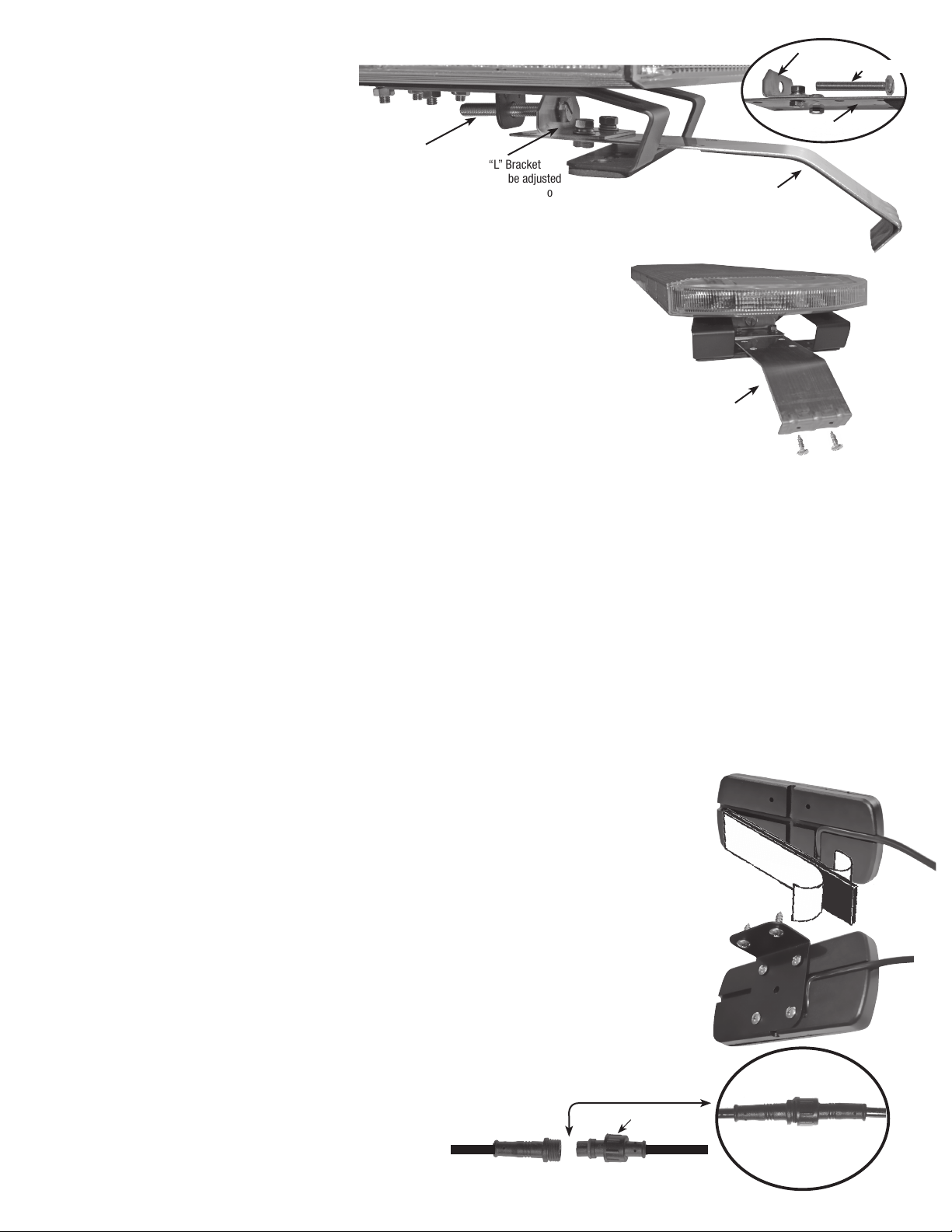
and nuts provided. Insert the tension
adjustment bolt through the strap’s
“L” bracket and thread bolt into the
light bar’s bracket, hand tighten.
IMPORTANT: The “L” bracket can be
repositioned for proper installation by
simply removing the bolt securing it to
the stainless-steel strap. Reposition
and secure the “L” bracket in preferred
location using the bolt, lock washer
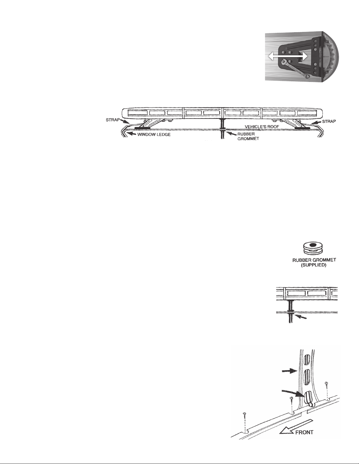
and nut. Repeat the procedure for other side of vehicle. WARNING:
The two-(2) stainless-steel straps, included with the light bar are universal
and should always be securely installed to the window’s ledge, using the
hardware provided. Some vehicles may require a custom designed strap to
properly secure the light bar to the vehicle’s window ledge. Always make sure
that both straps have a full hold on the vehicles window ledge. See Fig. 10.
21. Secure the two slide mounting brackets by rmly tighten the four nuts that
were loosened in step 1. See Fig. 5.
22. Tighten the two-(2) tension adjustment bolts evenly. While tightening the
bolts, make sure the light bar remains in the desired mounting position
on the roof. Torque bolts to 10 to 12 ft.- lbs. Failure to properly tighten the
tension adjustment bolts and straps could result in damage to the vehicle
and injury or death to the driver or others. IMPORTANT: Always inspect to make sure that both straps have a full
hold on the vehicles window ledge and the tension bolts are torqued correctly. See Fig. 10.
23. The hooked end of the stainless-steel strap that is engaged to the vehicle’s window ledge has two holes, which
will secure the bracket to the vehicle with the sheet metal screws provided. Use each of the holes in the bracket
as a guide and drill the required holes to size 11/64” into the window ledge. Secure the stainless-steel strap to
the window ledge with the sheet metal screws. IMPORTANT: The installer may have to lower headliner and
inspect the selected location to ensure that there are no components, wires and or any other vehicle part that
could be damaged by drilling. See Fig. 11.
24. Place the weather-stripping back into position on both sides of the vehicle.
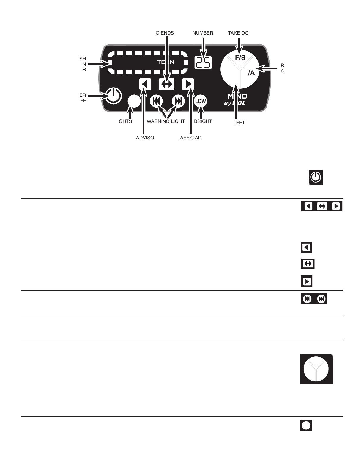
MOUNTING & WIRING SWITCH CONTROL PANEL
The light bar’s switch control panel needs to be mounted in a location that can easily be reached. WARNING: If
the vehicle is equipped with air bags, the installer MUST consult the vehicle’s shop or build manual to ensure that
light’s switch controller and wires will not affect deployment of air bags. This switch controller must be installed in
a location recommended by vehicle manufacturer. If necessary, consult manufacturer for their recommendation.
Failure to adhere to this warning could result in damage to the air bag and or reduce the
effectiveness of the air bag, which could result in bodily injury, or death to you or others.
25. NOTE: there are two methods to mount the switch controller, either by using the
double face tape provided or the metal mounting bracket, which is secured to the
mounting surface with screws. IMPORTANT: The installer must inspect the selected
location to ensure that there are no components, wires and or any other vehicle part
that could be damaged by drilling.
26. TAPE METHOD: Position the switch controller’s wire into the slots on the back panel.
Make sure the vehicle’s mounting surface is clean and free of dust, dirt, oil, wax
etc. Using the double face tape provided, secure the control panel to the selected
mounting location. See Fig. 12.
27. SCREW AND BRACKET METHOD: Position the switch controller’s cable into the
slots on the back panel so that the cable is ush with the back panel. Secure the
metal mounting bracket to the back of the switch controller with the four (4) screws
provided. Use the mounting bracket as a template, mark the two screw hole locations
and drill to size 11/16” and secure bracket with two (2) screws provided. See Fig. 13.
28. IMPORTANT: Connect the switch controller’s waterproof plug to the
light bars mating plug which was routed into the vehicle through the
access hole. The plugs can only be connected
in one position. Tighten the shoulder nut fully to
ensure a good waterproof connection. See Fig. 14.
Fig. 12
Fig.
13
Fig. 14
Can only connect in one
position. Match Notch
with Indent
Waterproof
Plug
Fig. 10
“L” Bracket
can be adjusted
to any holes on
Strap as needed
Tension
Adjustment Bolt
Strap
“L” Bracket
Strap
Tension Adjustment Bolt
Drill Hole Size
11/64"
Strap
Fig. 11
Shoulder
Nut

LUMINOUS™ 570 SERIES LED LIGHT BAR - PAGE 5
WIRING POWER CABLE
The Power Cable has two wires (red and black)
See Fig. 15.
29. WARNING: Failure to wire the light bar correctly could result in permanent damage to the light bar,
the vehicle’s electrical system and/or cause a re. If any electronic component parts, fuse or wire is
replaced, they must meet or exceed Wolo’s specications. Any deviation to the electrical specications
is at the installers/user’s risk. IMPORTANT: Disconnect the vehicles battery before beginning any wiring.
IMPORTANT: The warning lights RED wire must be connected directly to the inline fuse (included) at a
power source such as; the fuse block, the vehicle’s battery, or any 12 to 24 volt DC power source which is
rated by vehicle’s manufacturer capable of handling the amperage (see FUSE TABLE page 7). The inline
fuse should never be more than ten (10) inches from the power source. If either the red or black power
wires need to be lengthened use 18 gauge or heaver wire. The light bar is a low current device, to operate
this product at peak performance make sure all connections are clean of paint, rust and corrosion and
rmly secured.
30. RED & BLACK WIRES: Route the wires to the vehicles fuse block, accessory source or battery. If the
power wires pass through any drilled holes or rewall, always use a rubber grommet to protect the wire
cables.
31. BLACK WIRE: Connect to ground by securing wire under any metal body bolt or the negative (-) battery
post. Make sure that the METAL surface around the bolt that secures the wire is clean of rust, oxidation and
paint to make a good electrical connection.
32. RED WIRE: Connect to positive (+) 12 to 24 volts DC such as the fuse block, accessory power source in
the dashboard area or the positive (+) battery post. Always use the inline fuse holder provided with the
correct fuse, see Fuse Table on page 7 for correct fuse amperage. NOTE: The fuse holder will come with
the correct fuse for a 12-volt installation. The fuse to be used for 24-volt installation can be found in the
same hardware box as the fuse holder. Always use ATO or ATC type fuse.
33. To prevent shorts, make sure all wire connections are properly insulated and secured.
34. Make sure all wires are securely fastened to vehicle using plastic wire ties or electrical tape (not provided).
WARNING: Carefully inspect the interior driver’s area to make sure the light bar wires or the vehicle’s
electrical system wires are not interfering with the operation of vehicle’s controls; accelerator, brake, clutch
pedals etc.
35. Reconnect the vehicle’s battery. Installation is complete.
F/S
L/A R/A
LOW
M
FLASH PATTERN
LIGHT
PATTERN
LUMINOUS
By WOLO®
TM
Fig. 15
FUSE HOLDER
See Fuse Table on page 7
for correct fuse amperage.

LUMINOUS™ 570 SERIES LED LIGHT BAR - PAGE 6
OPERATING LIGHT BAR See Fig. 16.
36.
The switch controller has an on/off switch located at the bottom left corner, press and
release the button switch to turn the light bar ON/OFF. When the light bar is powered on the
switch controller’s digital pattern indicator will display the pattern number in use. The ash
pattern indicator may illuminate depending on what mode the switch controller is set to.
Trafc Advisory: There are three-(3) selectable trafc advisory light patterns to choose from.
The pattern in use will display on the switch controller’s ash pattern indicator and digital
indicator.
37. To power on trafc advisory: press and release the selected trafc indicated on the push
button switch. To turn off trafc advisory, press and release same button used to turn on.
Rear facing lights will ash from right corner to the left corner, the front facing warning
lights all LED clusters will ash on/off at the same time.
Rear facing lights will ash from the center to left and right corners. The front facing
warning light, all LED clusters will ash on/off at the same time.
Rear facing lights will ash from left corner to the right corner. The front facing warning
light, all LED clusters will ash on/off at the same time.
Warning light: There are twenty-nine-(29) selectable warning light patterns to choose from.
The pattern in use will display on the switch controller’s ash pattern indicator and will display
digitally showing a pattern number.
IMPORTANT: When switching the light bar from trafc advisory to warning lights, you need to
turn off the trafc advisory program by simply pressing and release the switch button for the
trafc advisory pattern in use, you will see the digital indicator change.
IMPORTANT: When the warning light is powered on the end LEDs (circular lens) have three
light pattern options to choose from.
38A Press L/A or R/A buttons once and the end LED lights (circular lens), will ash in
sequence with the light pattern in use.
38B Press L/A or R/A buttons twice and the end LED lights (circular lens), will change color to
clear and will function as an alley light illuminating steady on.
38C Press L/A or R/A buttons three times and the end LED lights (circular lens), will turn off.
38D 26B Press F/S button once and the two front center LED clusters will change color to
clear and will function as a powerful takedown light by illuminating steady on.
Using Alley and Takedown Lights without Warning lights
Press the M button once and the alley or takedown lights can be used without any warning
lights being illuminated.
F/S
L/A R/A
LOW
M
FLASH PATTERN
LIGHT
PATTERN
LUMINOUS
By WOLO®
TM
F/S
L/A R/A
LOW
M
FLASH PATTERN
LIGHT
PATTERN
LUMINOUS
By WOLO®
TM
F/S
L/A R/A
LOW
M
FLASH PATTERN
LIGHT
PATTERN
LUMINOUS
By WOLO®
TM
F/S
L/A R/A
LOW
M
FLASH PATTERN
LIGHT
PATTERN
LUMINOUS
By WOLO®
TM
F/S
L/A R/A
LOW
M
FLASH PATTERN
LIGHT
PATTERN
LUMINOUS
By WOLO®
TM
F/S
L/A R/A
LOW
M
FLASH PATTERN
LIGHT
PATTERN
LUMINOUS
By WOLO®
TM
F/S
L/A R/A
LOW
M
FLASH PATTERN
LIGHT
PATTERN
LUMINOUS
By WOLO®
TM
F/S
L/A R/A
LOW
M
FLASH PATTERN
LIGHT
PATTERN
LUMINOUS
By WOLO®
TM
F/S
L/A R/A
LOW
M
FLASH PATTERN
LIGHT
PATTERN
LUMINOUS
By WOLO®
TM
TRAFFIC ADVISORY
MIDDLE OUT TO ENDS
PATTERN
NUMBER
POWER
ON / OFF
FLASH
PATTERN
INDICATOR
TRAFFIC ADVISORY
RIGHT TO LEFT
BRIGHTNESSWARNING LIGHT
PATTERN
SELECTOR
TRAFFIC ADVISORY
LEFT TO RIGHT
ALLEY & TAKEDOWN LIGHTS
WITHOUT WARNING LIGHTS
FRONT SPOT
TAKE DOWN
RIGHT
ALLEY
LEFT
ALLEY
Fig. 16

LUMINOUS™ 570 SERIES LED LIGHT BAR - PAGE 7
Certication:
SAE J845Class 1: W3-1 19
California code of Regulation Title 13
ECE R10
UNECE R65
Operating voltage: 12-24 VDC
Construction: Heavy-duty extruded aluminum top and bottom
LED output: 3-Watts
LED type: 3030
Takedown dual color type: 5030
LED life span: 100,000 hours of use
29 Selectable light patterns
Length of power cable: 11.5 feet
Length of controller cable: 11.5 feet
Switch controller wire length: 5 feet
31 inch / 78 LEDs
48 inch / 126 LEDs
57 inch / 150 LEDs
SPECIFICATIONS
FLASH PATTERNS
CW = Clockwise CCW = Counter Clockwise
FUSE TABLE
Use ATO or ATC Type fuse
LENGTH OF
LIGHT BAR
12-VOLT FUSE
AMPERAGE
24-VOLT FUSE
AMPERAGE
31 Inch 10-Amp 7.5-Amp
48 Inch 15-Amp 10-Amp
57 Inch 15-Amp 15-Amp
12-VOLT
FUSE AMPERAGE
24-VOLT
FUSE AMPERAGE

LUMINOUS™ 570 SERIES LED LIGHT BAR - PAGE 8
WARRANTY
Wolo Manufacturing Corporation (“Wolo”) warranties to the original purchaser, for twelve months from the date of
purchase, that this product is free from defects in workmanship and materials. If there is such a proven defect, Wolo,
at its option, will either repair or replace the item free of charge, if it is returned to Wolo within twelve months from the
date of purchase together with proof of purchase as described below. Wolo reserves the right to inspect any defect prior
to settling any warranty claim by repair or replacement. This warranty is limited as above provided and Wolo will not be
responsible for re or other casualty or accident, due to neglect, abuse, abnormal use, modications, faulty installation
of this product, or natural causes.
ANY EXPRESSED WARRANTY NOT PROVIDED HEREIN IS EXCLUDED AND DISCLAIMED. THE IMPLIED
WARRANTIES OF MERCHANTABILITY AND OF FITNESS FOR A PARTICULAR PURPOSE ARE EXPRESSLY LIMITED
TO A TERM OF TWELVE (12) MONTHS. UNDER NO CIRCUMSTANCES SHALL WOLO BE LIABLE TO PURCHASER OR
ANY OTHER PERSON FOR ANY SPECIAL OR CONSEQUENTIAL DAMAGES, WHETHER ARISING OUT OF BREACH
OF WARRANTY OR OTHERWISE.
To obtain warranty service, return the product prepaid, and include the original bill of sale showing the date of purchase.
Provide with the return a brief description of the problem. Also, include with the return a check or money order in the
amount of $25.00 to cover return shipping.
Ship to:
Wolo Manufacturing Corp.
One Saxwood Street
Deer Park, NY 11729
Attn: Warranty Service
© 2020 Wolo Mfg. Corp.
All Rights Reserved
CLEANING
A scratched, dull or dirty lens can cause a reduction in brightness of the warning light. Never use a caustic or
petroleum-based cleaner on any surface of the warning light. For best cleaning results, always use household
glass cleaner or mild soap with a soft lint free rag. If the lens has scratches, or is dull, it is recommended those
components be replaced to ensure maximum brightness of the warning light.
Table of contents
Popular Automobile Accessories manuals by other brands

Westin
Westin 28-51315 installation instructions

Whelen Engineering Company
Whelen Engineering Company SAK57 installation guide

ABL
ABL Wallbox eM4 Single operating manual

aFe Power
aFe Power 54-82039 instruction manual

STO N SHO
STO N SHO SNS 38 Installation procedures

Thule
Thule Bed Rider 822/91822 Assembling instructions