1
Crosscut Setup:
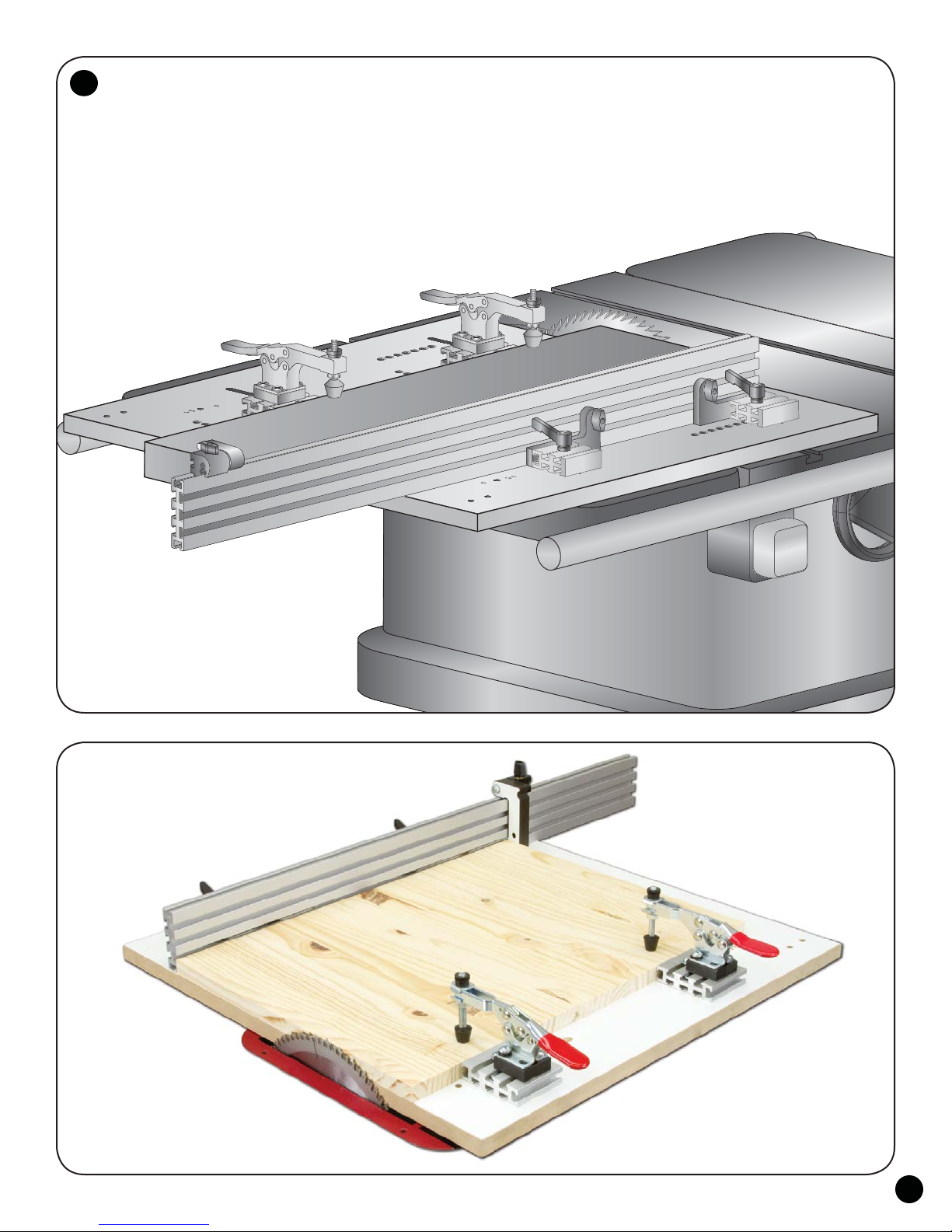
The Super Sled rides in the miter slot of the saw. Follow the instructions that come with
the Jig Bar (4924B), install the hardware in the bar and adjust the bar to fit the left or right miter
slot you've elected to use. These directions show the left miter slot being used.
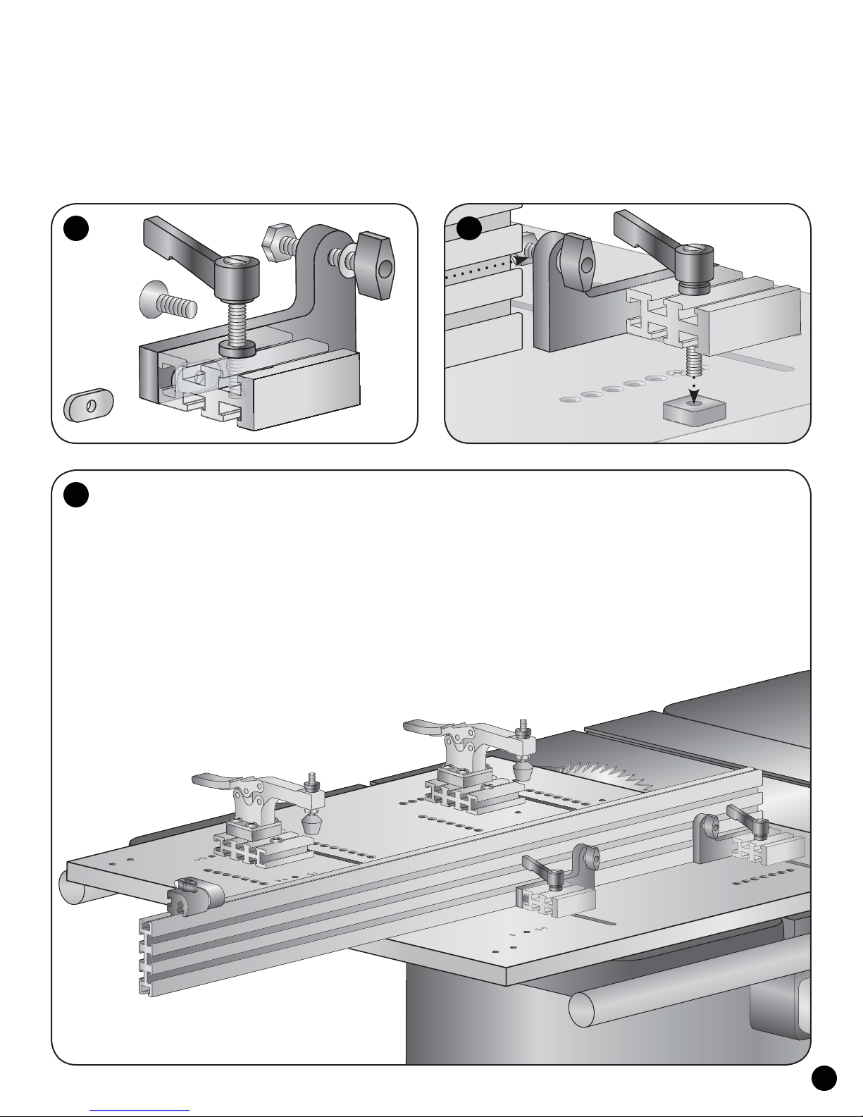
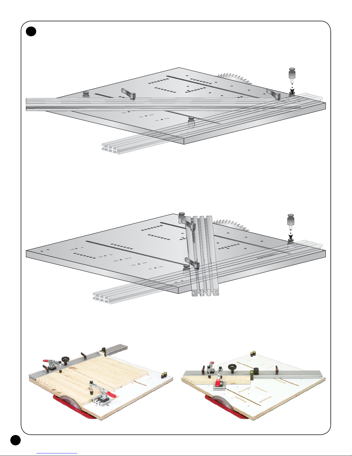
Lower the saw blade below the saw table. Place the Jig Bar, with the countersunk holes facing down, in the miter slot.
There are two sets of bar mounting holes in the Sled Base (4965B). One set is for crosscut work (Slots in Sled Base are
parallel to miter slot.) and the other set is for taper work (Slots in Sled Base are square to miter slot.). See fig. 1 & 2
Setup for crosscut work: Align the crosscut bar mounting holes in the Sled Base with the threaded holes in the Jig Bar,
positioning the Sled Base over the bar so that it doesn't overhang the cutting path of the saw blade by more than 1/2". Attach the
Jig Bar to the Sled Base with the 1" flat head screws (MF010) included in the 4924B hardware. After mounting the Jig Bar to
the Sled Base, recheck the fit of the Jig Bar in the miter slot, making sure it slides smoothly but without slop.
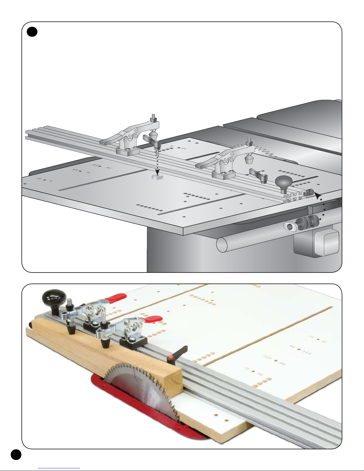
Raise the blade, turn the saw on and cut off the crosscut edge of the base overhanging the
saw blade (This should be no more than 1/2"!), guiding the bar/base assembly in the miter slot.
Turn the saw off, disconnect the power and lower the blade below the saw table.
MF010 x4
MF010 x4
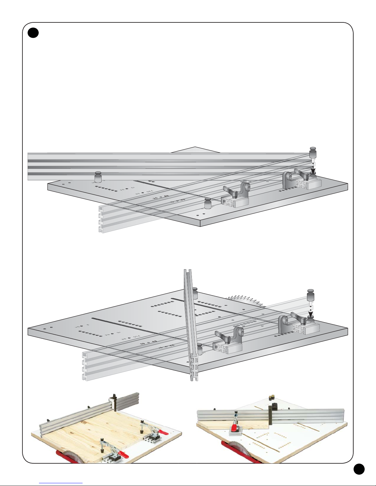
4965B Sled Base - Taper Setup
Slots in Base at 90º to blade
4965B Sled Base - Crosscut Setup
Slots in Base parallel to blade
Taper Setup:
Lower the saw blade below the saw table. Place the Jig Bar, with the countersunk holes facing down, in the miter slot.
There are two sets of bar mounting holes in the Sled Base (4965B). One set is for crosscut work (Slots in Sled Base are
parallel to miter slot.) and the other set is for taper work (Slots in Sled Base are square to miter slot.). See fig. 1 & 2
Align the taper bar mounting holes in the Sled Base with the threaded holes in the Jig Bar, positioning the Sled
Base over the bar so that it doesn't overhang the cutting path of the saw blade by more than 1/2". Attach the Jig
Bar to the Sled Base with the 1" flat head screws (MF010, in the 4924B hardware). After mounting the Jig Bar to
the Sled Base, recheck the fit of the Jig Bar in the miter slot, making sure it slides smoothly but without slop.
Raise the blade, turn the saw on and cut off the crosscut edge of the base overhanging the
saw blade (This should be no more than 1/2"!), guiding the bar/base assembly in the miter slot.
Turn the saw off, disconnect the power and lower the blade below the saw table.
When switching between crosscut and taper setups, leave the bar in the
miter slot to insure it's always remounted in its original position.
1
2