Woodhead 9200 Series User manual

SM3120-14F Page 1 of 7 ©Woodhead Feb-08
9200, 9300, 92400
Series Cable Reels SERVICE
MANUAL
IMPORTANT SAFETY INSTRUCTIONS
Please read this manual carefully and follow its instructions. Improper use or failure to follow these instructions could
result in serious injury, death or property damage. Operators should be instructed in the safe and proper use and
maintenance of this product. Keep this manual for future reference.
The following safety precautions call attention to potentially dangerous conditions.
DANGER: Immediate hazards which WILL result in severe personal injury or death.
WARNING: Hazards or unsafe practices which COULD result in severe personal injury or death.
CAUTION: Hazards or unsafe practices which MAY result in minor personal injury or product or
property damage.
INSTALLATION
WARNING:
Lock out all electrical power and remove all spring tension from the reel before opening
any enclosure or performing any service to this reel. Make sure all circuits carry
appropriate fuse protection. Hazards or unsafe practices COULD result in severe personal
injury or death.
WARNING: Failure to read, understand, and follow these instructions creates hazards that COULD
result in personal injury or death.
CAUTION: Instruct operators in the safe, proper use, and maintenance of the reel. Keep this manual
for future reference. Hazards or unsafe practices MAY result in minor personal injury or
product or property damage.
MOUNTING
The fixed base of the reel
allows mounting in several
different positions including
base up, base down, or wall
mounted. Here are general
mounting requirements:
•Main-shaft must be horizontal.
•Centerline of the spool assembly must be in line with the cable run.
•When mounted overhead in base up position, add a secondary chain, bracket or other safety device
to prevent reel from falling in case the mounting bolts are removed or become loosened by vibration.
DANGER: A secondary safety cable or chain is to be attached to all reels mounted overhead to prevent
reel from falling. Immediate hazards WILL result in severe personal injury or death.
All reels mounted over head should have a secondary support chain to protect personnel in case of
structure or mounting component failure. Attach one end of secondary support chain or cable to
secondary support point on reel. Attach other end of secondary support chain or cable to a support
component other than that which supports the reel. The chain or cable should be as short as possible
allowing reel to drop no more than 6 to 12 inches if the primary connection is released. A secondary
support is offered as an accessory item.
PIVOT BASE
If optional pivot base is used, four roller cable guide reel will align reel to direction of cable pull.

SM3120-14F Page 2 of 7 © Woodhead Feb-08
WIRING
NOTE: On model 228BH and CSA listed reels--in Canada--, the green wire has been grounded
to the frame of the reel and spool, and cannot be used as a power conductor.
A convenient one inch pipe thread opening has been provided at the bottom of the enclosure in
base for connecting standard water tight cable connectors or conduit fitting--fittings not supplied.
Individual power connections are made to the collector ring bus wires inside the junction box
enclosure in base using commercially available twist on wire connectors or compression splices.
amp 220 v
1 Phase 3 Phase
Wire Color Number
Wire Color Number
L1 black 1 L1 black 1
N white 2 L2 white 2
L3 red 3 L3 red 3
G green 4 G green 4
SAFETY INTERNAL GROUNDING
Standard reels are not grounded internally with the exception of reels built to CSA standards and the
model 228BH. Internal grounding must be accomplished by running a jumper wire from the brush
assembly to the spool grounding screw provided, and attaching the collector ring ground bus to the bolt
provided in the junction box enclosure on back of base. See main illustration and diagram.
WIRING SUPPLY CONNECTION
NOTE: See “Service, Working Cable Replacement/Installation” if cable needs to be installed.
ROLLER GUIDE AND SHEAVES
Cable must exit guide in-line with pulling direction. If not,
rotate guide arm as needed. The cable guide position is
set by rotating spring pocket assembly. Loosen the three
clamps holding spring pocket assembly in place by
unscrewing the three hex head bolts. Unless required, do
not completely remove bolts or clamps. Reposition guide
as required, making sure clamps straddle ribs on outside
diameter of spring pocket assembly and retighten hex
head bolts.
Sheaves are used to bend cable around corners. Typical
minimum bend radius of the sheave should be about 7.5 x
cable diameter. Requirements can vary depending on
cable manufacturer specifications. Sheaves should have
flat surfaces for cable to ride on. The movement of cable
through a sheave should be in the same plane as the cable
spool. Changing planes can greatly reduce cable life.
CABLE WINDING
There are many types of cable that may be installed on your cable reel depending on application. Select
the cable most appropriate for your application requirements. Many cables come from the factory with a
wax-like film that can encourage uneven wrapping. At initial set up it is common to use a dry lubricant
(talc powder), or silicone based grease to encourage more even winding. Also critical to proper winding
is the adequate setting of “Spring Tension”. See appropriate section. In some cases sheaves and
unanticipated application features can require more tension than offered with standard reels. Contact
factory for application assistance.

SM3120-14F Page 3 of 7 © Woodhead Feb-08
OPERATION
RATCHET LOCK
All models are supplied with a ratchet lock that
works in any position. If ratchet lock is not
required--constant tension--
, move spring clip and
spring to adjacent cable guide screw.
SPRING TENSION
CAUTION: Do not connect working end of cable until the reel is properly pretensioned. Hazards or
unsafe practices MAY result in minor personal injury or product or property damage.
CAUTION: Failure to test for adequate spring revolutions can cause spring damage. Hazards or
unsafe practices MAY result in minor personal injury or product or property damage.
NOTE: A minimum 2 pre-tension turns is required. Additional turns can added as long as one
unused spring turn remains when cable is fully extended. If entire cable cannot be pulled
out, decrease spring tension until full one turn remains.
Reels shipped with cable end
attachments (handlamps, plugs,
etc.) are pre-tensioned at
factory. All other reels require
pretensioning turns to spool
assembly before connecting
free end of working cable. Set
spring tension by turning fully
wrapped reel through a specific
number of revolutions or turns.
Number of pretension turns depends on application and desired tension. A minimum of 2 set up turns
is needed for most applications. Additional tension may be added by repeating above process. After
tension is set, connect cable free end. Failure to pretension reel may result in insufficient tension to
retract and may shorten spring life.
SERVICE
BULB REPLACEMENT--model 228BH
CAUTION: Always check for shorts and continuity before turning on electrical power. Hazards or
unsafe practices MAY result in minor personal injury or product or property damage.
Remove guard on hand lamp by removing screws on base of guard.
NOTE: Use a 75-watt or smaller bulb. A rough service bulb is recommended.
MAINSPRING
WARNING:
Always disconnect electrical power before dismantling any part of the reel. Fuse size
must not be greater than maximum amperage capacity of cable. Remove all spring
tension before attempting any service. Hazards or unsafe practices COULD result in
severe personal injury or death.
WARNING: To prevent personal injury, death or property damage, handle all springs with care. Use
suitable protective gloves for spring handling. Hazards or unsafe practices COULD
result in severe personal injury or death.
WARNING: To prevent personal injury, death or property damage, hold center of spring down as the
hub is pulled out. If the center is allowed to rise up, the spring may escape from its
container. Hazards or unsafe practices COULD result in severe personal injury or death.

SM3120-14F Page 4 of 7 © Woodhead Feb-08
If reel will not develop tension or retract cable, spring assembly may need to be replaced. Remove
junction box cover. Disconnect line-input wires from collector ring bus wires. Also disconnect cable free
end and allow spring to unwind completely. Remove screw, shaft retainer, the pull complete spool
assembly with cable from base. Remove cable guide, spring clip, ratchet spring, shoulder bolt and
ratchet pawl from spring pocket assembly. Remove spring pocket assembly from base and replace with
new part. To reassemble, reverse the above procedure making sure the dimple in the shaft retainer is
toward the main shaft. Re-tension cable reel as per instructions.
COLLECTOR RING REPLACMENT
WARNING: Disconnect and lock out all power to reel and remove all tension on spring before
servicing collector ring assembly. Hazards or unsafe practices COULD result in severe
personal injury or death.
CAUTION: Check continuity and replace all covers before turning on electrical power. Hazards or
unsafe practices MAY result in minor personal injury or product or property damage.
WARNING: Check placement of brush holder assemblies to make sure terminal locations are
centered between the protruding lobes on the inner and outer drums. Hazards or unsafe
practices COULD result in severe personal injury or death.
NOTE: Check position of cable entry in relationship to studs marked by “X” in figure. Replace
subsequent brush assemblies in clockwise rotation
To service the collector ring
assembly, remove junction box
cover and disconnect bus wires in
junction box. Remove cover, if
required, and outer drum-half.
Unclip brush assembly from brush
studs and remove. Notice position
of brush assembly. Remove all
brush assemblies from collector
ring. Loosen collector ring set
screw & slide collector ring off
main shaft. To reassemble,
reverse above procedure.
The last brush assembly--one
closest to steel hub on collector
ring--must be assembled on brush
studs indicated by the “X” in the
figure BELOW.
WORKING CABLE REPLACEMENT/INSTALLATION
WARNING: Disconnect and lock out all power to reel and remove all tension on spring before
servicing collector ring assembly. Hazards or unsafe practices COULD result in severe
personal injury or death.
CAUTION: Check continuity and replace all covers before turning on electrical power. Hazards or
unsafe practices MAY result in minor personal injury or product or property damage.
NOTE: Cable seal is a bellows type seal designed to fit different size cables. Pull out the
bellows in one direction and cut the seal so that the through opening is at least 1/8"
diameter smaller than the working cable. Always cut the seal smaller than required.
More of the seal may be cut off if necessary.
The procedure below applies to both new installations and for replacement of working cable. To
install/replace cable loosen seal cover and cable seal. Remove cover, if required, and outer drum half.
Loosen or remove cable clamp & individual conductors of working cable from brush assemblies. Pull
working cable through opening of inner drum & remove seal cover, & cable seal from old working cable.

SM3120-14F Page 5 of 7 © Woodhead Feb-08
Place seal cover and cable seal over replacement cable. To reassemble, reverse the above procedure.
Be sure to connect working cable conductors to the proper brush assembly. Re-tension spring .
REPLACEMENT PARTS

SM3120-14F Page 6 of 7 © Woodhead Feb-08

SM3120-14F Page 7 of 7 © Woodhead Feb-08
POW-R-MITE REEL REFERENCE CHART FOR REELS WITH CABLE INCLUDED.
Reel Includes Cable:
Model Cable
Number Length
(ft) Size OD” Reel w/o
Cable #
9224 85-1630 31 16-3 .430 095105203
9228 85-1630 51 16-3 .430 095105203
9234 85-1640 31 16-4 .485 095105204
9238 85-1640 51 16-4 .485 095105204
9253 85-1430 26 14-3 .560 095105203
9358 85-1430 51 14-3 .560 095104203
9363 85-1440 26 14-4 .605 095104204
9367 85-1440 46 14-4 .605 095104204
9383 85-1230 26 12-3 .640 095104203
9385 85-1230 36 12-3 .640 095104203
9394 85-1240 31 12-4 .670 095104204
9242 85-1030 21 10-3 .695 095105203
9206 86-1660 46 16-6 .565 095105206
9208 86-0202 39 16-8 .645 095105208
9306 85-0506 36 14-6 .740 095104206
9308 86-0203 21 14-8 .795 095104208
92481 86-0202 51 16-8 .645 095106208
92401 AMR62120150 31 16-10 .720 095106210
92411 87-0108 31 16-12 .740 095106212
92482 86-0203 31 14-8 .845 095106208
92402 86-0803 21 14-10 .905 095106210
92433 85-1230 51 12-3 .640 095106203
92443 85-1240 41 12-4 .670 095106204
92463 85-0508 31 12-6 .800 095106206
92483 86-0204 21 12-8 .915 095106208
92434 85-1030 41 10-3 .695 095106203
92444 85-1040 31 10-4 .750 095106204
92464 85-0510 21 10-6 .880 095106206
Reference
Number
Part Number
Qty.
Description
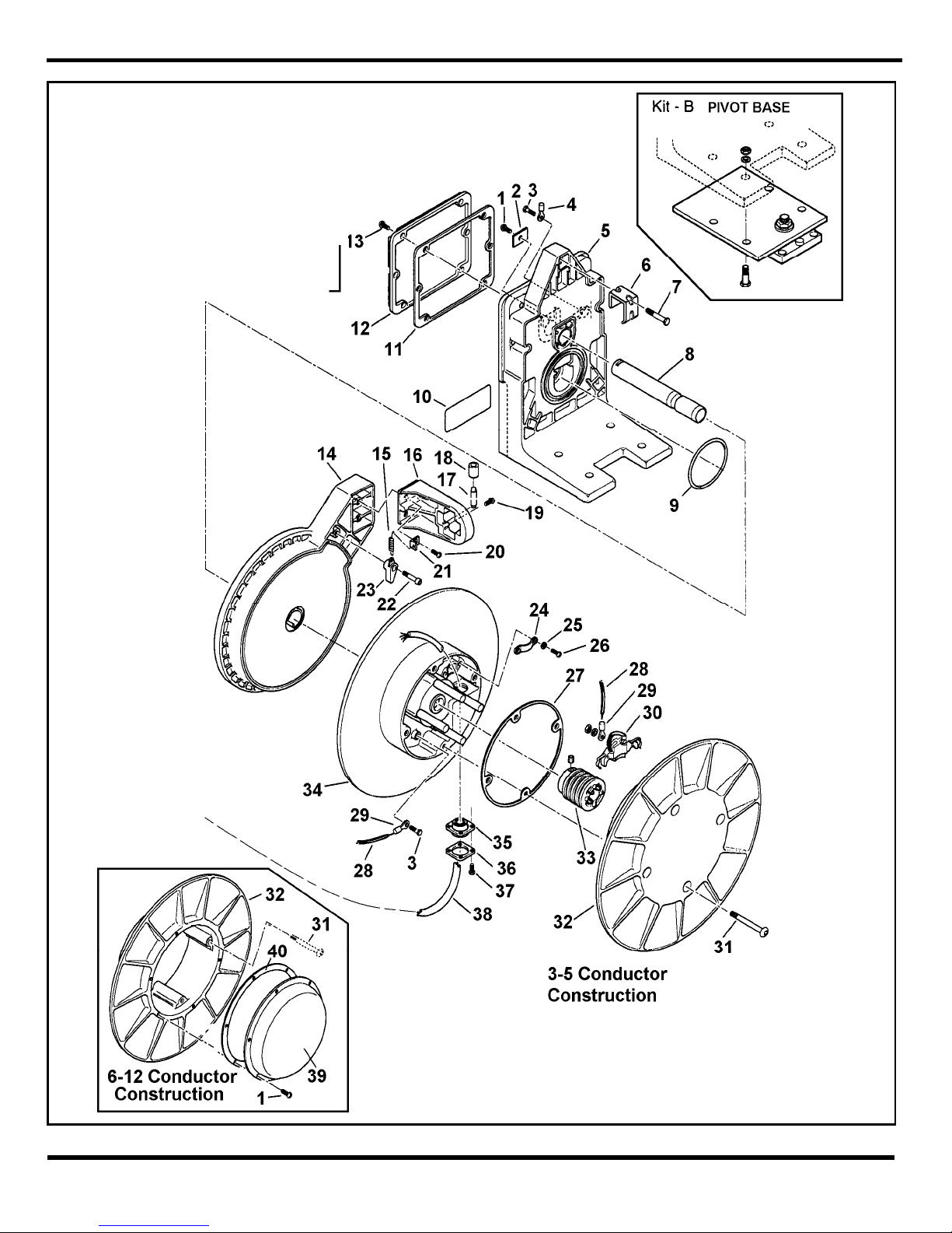
AMC03500231 1 Screw pan head M5x12mm
1 AMC03500231 7 Screw pan head m5x12mm 6-12 conductors
2 AMM41100003 1 Shaft retainer
3 AMC03510130 2 Bolt hex head M5x10mm
AM00041P0127 1 Terminal - for #10-#12 AWG wire
4 AM00041P0126 1 Terminal - for #16-#14 AWG wire
5 AMM04160004 1 Base
6 3 Clamp-Included in Clamp Kit “D” below.
7 3 Bolt hex head M6-Included in Clamp Kit “D” below.
AMM34370002 1 Main shaft – 3 to 5 conductors
AMM34370003 1 Main shaft – 6 to 8 conductors
8 AMM34370004 1 Main shaft – 10 to 12 condcutors
9 AMC47040141 1 O-ring
10 1 Name plate
11 AMM14240007 1 Junction box gasket
12 AMM04540004 1 Junction box cover
13 AMC03500253 6 Screw pan head M6x16mm
AMH41220074 1 Spring pocket assembly -- 0951-04-xxx
AMH41220075 1 Spring pocket assembly -- 0951-05-xxx
AMH41220076 1 Spring pocket assembly -- 0951-06-xxx
AMH41220078 1 Spring pocket assembly -- 0951-08-xxx
14
AMH41220079 1 Spring pocket assembly -- 0951-09-xxx
15 AMC60610121 1 Extension spring
16 AMM04730007 1 Cable guide frame See Kit “E”
17 AMM24060125 4 Roller shaft See Kit “E”
18 AMM86700006 4 Roller See Kit “E”
19 AMC03500253 4 Screw pan head M6x16mm See Kit “E”
20 AMC03500255 2 Screw pan head M6x20mm See Kit “E”
21 AMM53350002 1 Spring clip
22 AMC15070225 1 Screw shoulder M8x10x16
23 AMM86750002 1 Ratchet pawl
24 AMM70780007 1 Cable clamp
25 AMC01070517 2 Flat washer M5
26 AMC03500233 2 Screw pan head M5x16 OD .380-.539

SM3120-14F Page 8 of 7 © Woodhead Feb-08
AMC03500235 2 Screw pan head M5x20 OD .540-.699
AMC03500237 2 Screw pan head M5x25 OD .700-.925
27 AMM14210026 1 Drum gasket -- Included in Drum Kits “C” below
28 AMR61210586 .5 ft Wire - green #10 -- ground only
AM00041P0126 2 Terminal - ground only -- AWG #16 and #14
29 AM00041P0127 2 Terminal - ground only -- AWG #10 and #12
30 AM6050500000 AR Copper brush assembly - quantity one per 9th digit
31 4 Screw -- Included in Drum Kits “C” below
32 1 Outer drum half -- Included in Drum Kit “C” below
AM5856700021 1 Collector ring subassembly – 3 cond.
AM5856700022 1 Collector ring subassembly – 4 cond.
AM5856700023 1 Collector ring subassembly – 6 cond.
AM5856700024 1 Collector ring subassembly – 8 cond.
AM5856700009 1 Collector ring subassembly – 10 cond.
33
AM5856700011 1 Collector ring subassembly – 12 cond.
34 1 Inner drum half -- Included in Drum Kit “C” below
35 AMM86550002 1 Cable seal
36 AMM37810027 1 Seal cover
37 AMC03500201 4 Screw, cheese head M4x12mm
38 See chart AR Cable
AM5876200000 1 Cover – 6 to 8 conductor
39 AM5876100000 1 Cover – 10 to 12 conductor
40 AM4350600000 1 Gasket – 6 to12 conductor
Kit B 9501 1 Pivot base – optional
AMH05040001 AR Drum Kit - 3, 4 & 5 Cond. -- Includes Reference Numbers 27, 31, 32 & 34
AMH05040002 AR Drum Kit - 6 & 8 Cond. -- Includes Reference Numbers 27, 31, 32 & 34
Kit C AMH05040003 AR Drum Kit – 10 & 12 Cond. -- Includes Reference Numbers 27, 31, 32 & 34
KIT D AMH05040013 1 Clamp Kit; 3 sets, Stainless Steel-Includes Reference Numbers 6 & 7.
KIT E AMH26340009 1 Roller Guide Kit Reference Numbers 16, 17, 18, 19 & 20.
Above parts are all painted Yellow
This manual suits for next models
30
Table of contents
Popular Cables And Connectors manuals by other brands

Drone
Drone X1 MAX installation guide

COMSOL
COMSOL HD102 user manual

nedis
nedis VSPL3478AT quick start guide

3Com
3Com SS II ADVANCED RPS PWR Y-CABLE user guide

Dormont
Dormont Blue Hose Installation & operating instructions

Siemens
Siemens SIMATIC 6ES7158-3MU10-0XA0 Hardware Installation and Operating Manual