6 Safety MAN1354
(01/24/2024)
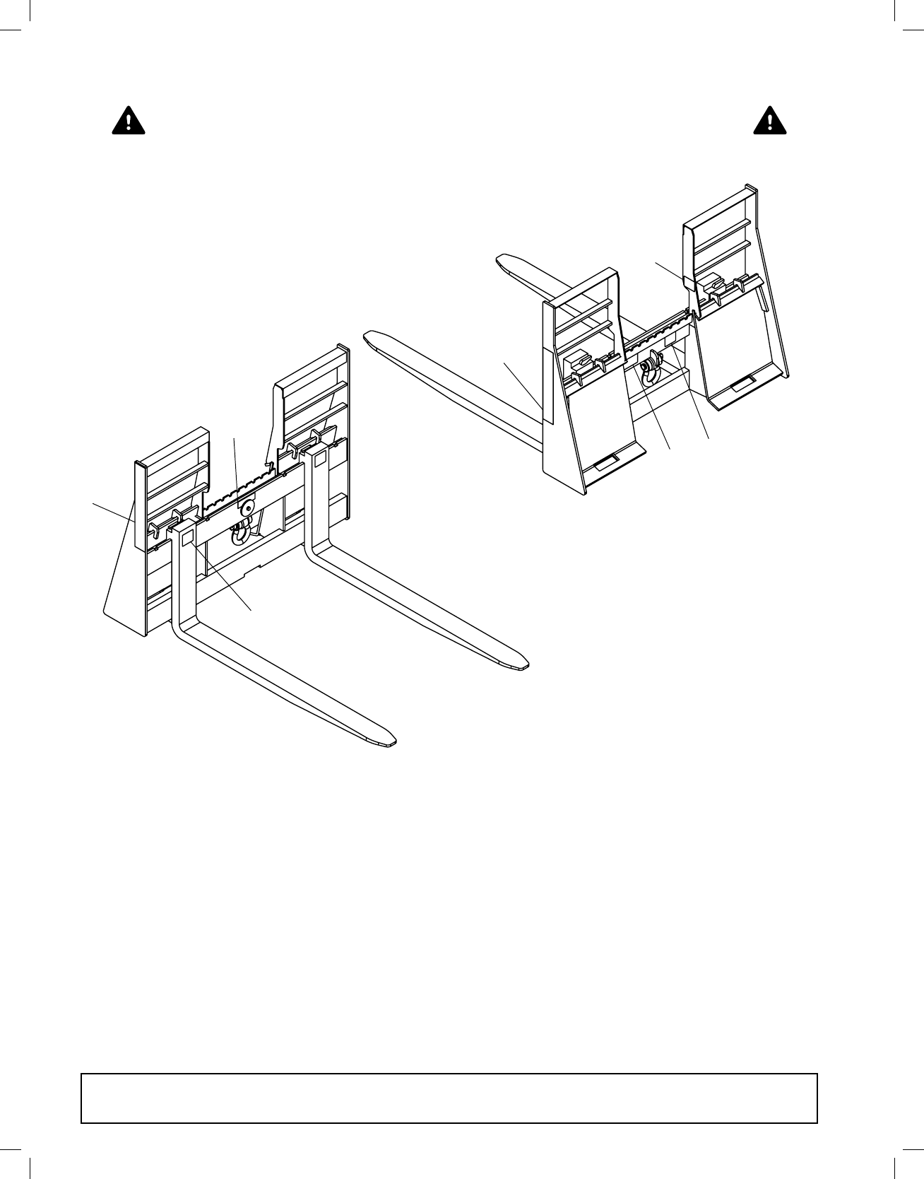
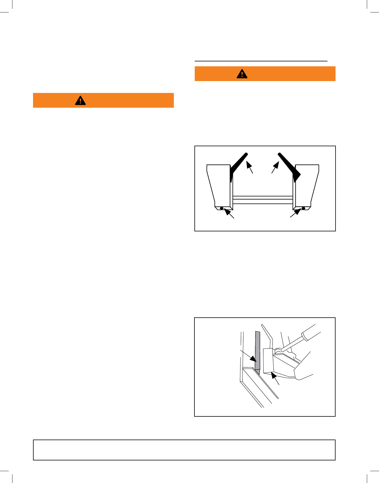
■Do not put Pallet Fork into service without
forks properly engaged on frame rails and fork
lockplate secured in place. Fork locks must
be engaged into fork lock notches. Replace if
damaged.
■Consult local utilities before digging. Know lo-
cation and depth of all underground cables,
pipelines, and other hazards in working area
and avoid contact.
■Contact with high voltage, overhead power
lines, underground cables, gas lines, and other
hazards can cause serious injury or death from
electrocution, explosion, or re.
■Keep bystanders away from equipment.
■Do not operate or transport equipment while
under the inuence of alcohol or drugs.
■ Operate only in daylight or good articial light.
■Keep hands, feet, hair, and clothing away from
equipment while engine is running. Stay clear of
all moving parts.
■Always comply with all state and local lighting
and marking requirements.
■Do not allow riders. Do not lift or carry anybody
on the power unit or attachments.
■Always sit in power unit seat when operating
controls or starting engine. Securely fasten
seat belt/operator restraint, place transmission
in park or neutral, engage brake and ensure all
other controls are disengaged before starting
power unit engine.
■Look down and to the rear and make sure area is
clear before operating in reverse.
■Use extreme care when working close to fences,
ditches, other obstructions, or on hillsides.
■Use caution when handling loose or shiftable
loads.
■Do not operate or transport on steep slopes.
■Allow for forklift length when making turns.
■Stop the forks gradually when lowering or lifting.
■Do not stop, start, or change directions sudden-
ly on slopes.
■Use extreme care and reduce ground speed on
slopes and rough terrain.
■Watch for hidden hazards on the terrain during
operation.
■Stop power unit and implement immediately
upon striking an obstruction. Dismount power
unit, using proper procedure. Inspect and repair
any damage before resuming operation.
■Leak down or failure of mechanical or hydraulic
system can cause equipment to drop.
■AVOID INJURY OR DEATH FROM FALLING
OBJECTS:
• Do not carry shiftable items. Hay bales, logs,
fence posts, stones, and other objects can
roll or fall from a raised attachment and
crush operator or children, bystanders or
animals.
• This unit is not equipped with any method to
prevent objects such as round bales, posts,
or logs from rolling back onto operator.
• Do not handle round hay bales.
• Carry loads low and drive slowly.
• Do not carry large objects that can fall out of
attachment into operator zone.
• Never lift load higher than necessary to clear
the ground when moving.
■Before leaving operator’s seat, lower lift arms
and put attachment on the ground. Engage
brake, stop engine, remove key, and remove
seat belt.
MAINTENANCE
■NEVER GO UNDERNEATH EQUIPMENT. Never
place any part of the body underneath equip-
ment or between moveable parts even when the
engine has been turned off. Hydraulic system
leak-down, hydraulic system failures, mechan-
ical failures, or movement of control levers can
cause equipment to drop or rotate unexpectedly
and cause severe injury or death.
• Service work does not require going
underneath.
• Read Operator’s Manual for service in-
structions or have service performed by a
qualied dealer.
■Before performing service work that requires re-
pair or replacement of parts, remove attachment
from power unit. Hydraulic system failures, me-
chanical failures, or movement of control levers
can cause equipment to drop or rotate unex-
pectedly and cause severe injury or death.
■Do not modify or alter or permit anyone else to
modify or alter the equipment or any of its com-
ponents in any way.
SAFETY RULES
ATTENTION! BECOME ALERT! YOUR SAFETY IS INVOLVED!
MAN1354_2024-01.indd 6MAN1354_2024-01.indd 6 1/24/24 12:37 PM1/24/24 12:37 PM