manuals.online logo
Brands
  1. Home
  2. •
  3. Brands
  4. •
  5. Woodstock Soapstone
  6. •
  7. Stove
  8. •
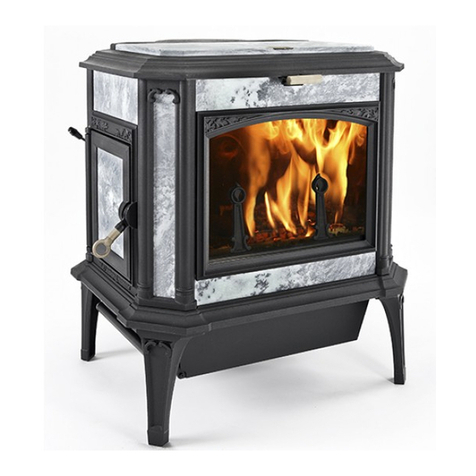
  9. Woodstock Soapstone Fireside Franklin User manual

Woodstock Soapstone Fireside Franklin User manual

Introduction:
Your Fireside Franklin gas stove is surprisingly
simple and inexpensive to install. Direct vent pipe can be
installed virtually anywhere, through a wall or ceiling.
Whether you’re a do-it-yourselfer or hire an outside
installer, this guide will allow you to begin planning the
installation that best suits your needs. There are always
exceptions, and should you need assistance or advice at
any time in the process, please call our expert and experi-
enced staff at (800) 866- 4344.
What You Can Do Before You Purchase
A Fireside Franklin Gas Stove
You can, and should, figure out how and where
you are going to install your stove before it arrives. Use
this guide to help determine whereyou will run the vent
pipe. The termination cap is hot, so you will want to keep
it away from places where there is heavy traffic. Clearance
requirements don’t allow the termination cap to be within
12 inches of a window that opens or ventilation air supply
inlets, for example. Use this guide to determine whether
your intended location will work.
I. Choice of 6 Different Ways To Vent
The Fireside Franklin
The Fireside Franklin gas stove is approved for
venting in SIX (6) configurations. See Gas Stove Brochure
PDF for illustrated examples of venting installations and
the parts required for each installation.
1. Straight up vertically through the roof with a maxi-
mum height of 24 feet.
2. Up and out, with a horizontal run of 4’ or less.The
maximum horizontal run is four feet in all cases. You
must also ensure a 1/4 inch rise per foot of horizontal
run (1 inch of rise for 4 feet of run). If you have 4 feet
of horizontal run, the maximum allowable chimney
height is 20’
3. Straight back,
through an exterior
wall, and into a
“snorkel termination
cap.” The “snorkel”
goes up the outside
of the building a total
of three feet, and pro-
vides draft.
4. Into a masonry chim-
ney with an existing
single flue and a maxi-
mum height of 24 feet
and minimum inner flue diameter of 6”.
5. Into an existing fireplace with a maximum height of
24feet and a minimum inner flue diameter of 6”.
6. Into an existing prefabricated metal chimney with a
maximum height of 24 feet and a minimum inner
diameter of 6”.
System Requirements:
A. The venting system must have two (2) feet of vertical
rise for every one (1) foot of horizontal run.
B. The total length of the venting system must be calculat-
ed to plan your installation. Deduct 3 feet for each 90-
degree elbow and 1.5 feet for every 45-degree elbow
from the total amount of lineal travel allowed by an
installation (excluding the 90 or 45 attached as the
first piece of venting to the fireplace).
II. Plan Stove Location and Clearances
The Fireside Franklin gas fireplace is designed to
have close clearances to the rear and sides of the appli-
ance. Toensureyour safety and proper functioning of the
fireplace, these clearances must be maintained. Below are
the minimum clearances allowed:
4Installing the Fireplace in the corner of a room, the rear
corners of the fireplace must sit a minimum of 2 inches
from the corner walls on both sides of the fireplace.
4In installations other than a corner,the rear of the fire-
place must be a minimum of 10 inches from the wall
behind it and the sidewalls of the fireplace must be a
minimum of 8 inches from any adjacent walls.
(Clearance to the wall in an “up and out” installation
will be determined by the combined radii of the two
elbows, and will be approximately 12”.)
4In the case of an alcove installation the minimum
height from the top of the stove to the ceiling is 56
inches (or 84 inches from floor to ceiling).
4Direct vent pipe for your fireplace must at no time be
any closer to a wall than 2 inches, or closer to a ceiling
than 6 inches.
4Your Fireside Franklin must also be placed on a non-com-
bustible surface, such as ceramic tile, stone, brick, or metal.
The surface must be 24 inches by 30 inches (we recommend
ahearth of 36 inches by 36 inches) or greater to provide ade-
quate safety and protection to you and your home.
Preliminary Installation Guide
for the Fireside Franklin Gas Stove
How to calculate lineal footage:
For example, if you need to travel 4 feet
vertically and 2 feet horizontally to a ter-
mination cap, your lineal footage is 9 feet.
9’ is the sum of the following: 0’ (elbow at
stove) + 4’ (straight venting) + 3’ (elbow)
+ 2’ (straight venting) = 9’.
An outside "snorkel"
allows straight-back
venting, with a 36" rise
outside of the building.

III. Termination Clearances:
The vent pipe must terminate outside the home with
clearances adequate to protect against heat and against
exhaust re-entering the house. Below are the approved
minimum clearances for the termination cap of your
Fireside Franklin gas fireplace:
uFor vertical terminations the direct vent pipe must
extend 1.5 to 2 feet above the roof surface.
uA minimum of 12 inches must be maintained from:
;Permanently closed window (RIGHT “A”)
;Door or window that may be opened (RIGHT “B”)
;Clearance above grade (RIGHT “C”)
;Below deck, veranda, or balcony (RIGHT “C”)
;Non-mechanical air supply inlet, combustion inlet
or any other appliance inlet (RIGHT “D”)
;Inside corner or adjacent wall (RIGHT “E”)
;Non-ventilated soffit (BELOW “F”)
uA minimum of 18 inches must be maintained from:
;Deck, porch, veranda, balcony in a vertical direction
(RIGHT “G”)
;Ventilated soffit located above the termination cap
(RIGHT “H”)
uA minimum of 3 feet must be maintained from:
;Centerline of a service regulator (BELOW LEFT “I”)
;Vegetation (BELOW LEFT “J”)
Minimum Clearances: Corner Installation
2
2"
"
2
2"
"
Minimum Clearances: Parallel Installation
*2” clearance can only be achieved with a
straight-up vertical vent configuration.
2
2"
"*
*
8
8"
"
G
Gr
ra
ad
de
e
A
Ai
ir
r
N
No
on
n
M
Me
ec
ch
ha
an
ni
ic
ca
al
l
A
Ai
ir
rS
Su
up
pp
pl
ly
y
G
G
D
D
H
H
E
E
C
C
R
Ro
oo
of
f
D
De
ec
ck
k
A
A
E
E
B
B
C
C
M
Me
ec
ch
ha
an
ni
ic
ca
al
l
A
Ai
ir
rS
Su
up
pp
pl
ly
y
V
Ve
eg
ge
et
ta
at
ti
io
on
n
R
Ro
oo
of
f
K
K
I
I
L
L
J
J
F
F
B
B
M
M
N
No
on
nv
ve
en
nt
ti
il
la
at
te
ed
d
S
So
of
ff
fi
it
t
P
Pu
ub
bl
li
ic
cS
Si
id
de
ew
wa
al
lk
ko
or
r
D
Dr
ri
iv
ve
ew
wa
ay
y
+VERY IMPORTANT NOTE:
Connections Betwen Components
Simpson Dura-Vent GS system 6 5/8” venting is the
only approved system for use with your Fireside
Franklin gas fireplace. These venting systems have
an interconnection locking system built into each
vent piece allowing a safe and secure connection
without need for additional hardware or tools. It is
critical to the effective heating, proper flame pattern
and your safety to ensure that each connection is
completely secure. This is accomplished by assem-
bling the venting with the female end toward the
stove, pushing them together and twisting the piece
to be connected in a clockwise direction 1/8 of a turn
until it comes to a positive stop in the locked posi-
tion. During the initial connection, you’ll need to
ensure that the inner pipes are overlapping, as this
cannot be checked from the outside of assembled sec-
tions.
Horizontal termination caps must be positioned 12-18 inches above
grade, and 12-18 inches away from windows, decks, soffits, and non-
mechanical air supplies.
Service regulators and vents should be located away from vegetation,
driveways, sidewalks, and other high traffic areas.
uAminimum of 6 feet must be main-
tained from:
;Service regulator vent outlet
(BELOW LEFT “K”)
;Mechanical air supply (BELOW
LEFT “L”)
uAminimum of 7 feet must be main-
tained above:
;A paved driveway or sidewalk on
public property (BELOW
LEFT “M”)
Venting may NEVER terminate above a
sidewalk or driveway that is between
two single-family dwellings and services
both.
V
Ve
en
nt
ti
il
la
at
te
ed
d
S
So
of
ff
fi
it
t
F
Fi
ix
xe
ed
d
W
Wi
in
nd
do
ow
w

Other Woodstock Soapstone Stove manuals

Woodstock Soapstone NAVAJO Hybrid Instruction manual

Woodstock Soapstone

Woodstock Soapstone NAVAJO Hybrid Instruction manual

Woodstock Soapstone 209 User manual

Woodstock Soapstone

Woodstock Soapstone 209 User manual

Woodstock Soapstone 211 Navajo Hybrid User manual

Woodstock Soapstone

Woodstock Soapstone 211 Navajo Hybrid User manual

Woodstock Soapstone 211 Navajo Hybrid User manual

Woodstock Soapstone

Woodstock Soapstone 211 Navajo Hybrid User manual

Woodstock Soapstone Cottage Franklin 207 User manual

Woodstock Soapstone

Woodstock Soapstone Cottage Franklin 207 User manual

Woodstock Soapstone 210 User manual

Woodstock Soapstone

Woodstock Soapstone 210 User manual

Woodstock Soapstone KEYSTONE 204 User manual

Woodstock Soapstone

Woodstock Soapstone KEYSTONE 204 User manual

Woodstock Soapstone KEYSTONE 204 User manual

Woodstock Soapstone

Woodstock Soapstone KEYSTONE 204 User manual

Woodstock Soapstone Keystone User manual

Woodstock Soapstone

Woodstock Soapstone Keystone User manual

Popular Stove manuals by other brands

Breckwell Cadet P20FS owner's manual

Breckwell

Breckwell Cadet P20FS owner's manual

Clarke BOXWOOD user guide

Clarke

Clarke BOXWOOD user guide

EdilKamin LOGO Installation, use and maintenance

EdilKamin

EdilKamin LOGO Installation, use and maintenance

Jøtul F 305 manual

Jøtul

Jøtul F 305 manual

Anslut 005509 operating instructions

Anslut

Anslut 005509 operating instructions

MCZ LINEA Comfort Air installation guide

MCZ

MCZ LINEA Comfort Air installation guide

Cadel GO 11 Installer manual

Cadel

Cadel GO 11 Installer manual

Konigshutte Vela 28/875 instruction manual

Konigshutte

Konigshutte Vela 28/875 instruction manual

Divina Clarinda 170 user manual

Divina

Divina Clarinda 170 user manual

Candy TRI 5S Instructions for use and installation

Candy

Candy TRI 5S Instructions for use and installation

Powerfix E035904 Operation and safety notes

Powerfix

Powerfix E035904 Operation and safety notes

Hunter Stoves Herald 6 CE VII Installation and servicing instructions

Hunter Stoves

Hunter Stoves Herald 6 CE VII Installation and servicing instructions

Moretti Design TECNIKA FOR HOME DEDICATED MANUAL

Moretti Design

Moretti Design TECNIKA FOR HOME DEDICATED MANUAL

Ravelli OLIVIA STEEL manual

Ravelli

Ravelli OLIVIA STEEL manual

MCZ SUITE COMFORT AIR 14 M1 installation guide

MCZ

MCZ SUITE COMFORT AIR 14 M1 installation guide

Bell Tent Tipi How-to guide

Bell Tent

Bell Tent Tipi How-to guide

Primus 2243 user manual

Primus

Primus 2243 user manual

Nordpeis Quadro user manual

Nordpeis

Nordpeis Quadro user manual

manuals.online logo
manuals.online logoBrands
  • About & Mission
  • Contact us
  • Privacy Policy
  • Terms and Conditions

Copyright 2025 Manuals.Online. All Rights Reserved.