Woodway Whelen CenCom Sapphire User manual

Woodway Engineering Ltd
Lower Road, Barnacle
Coventry, CV7 9LD
United Kingdom
Tel: +44 (0) 24 76 841750
Fax: +44 (0) 24 76 621796
www.woodwayengineering.com
INSTALLATION GUIDE
®�
CenCom Sapphire™

Woodway Engineering Ltd
Lower Road, Barnacle
Coventry, CV7 9LD
United Kingdom
Tel: +44 (0) 24 76 841750
Fax: +44 (0) 24 76 621796
www.woodwayengineering.com INSTALLATION GUIDE
2
®�
(+)
Battery
(-)
USB
WC Lightbar
Optional Microphone Extension
Cord Shown For Reference Only
N1
N2
N3
N4
N5
N6
N7
N8
4
5
6
7
8
Postive outlets
10 Amps each
No Connection
Negative outlets
2 Amps each
5 to 10 Logical Inputs
Sirens Drivers Output
Max 50 Amp Fuses
2
1
40 Amps combined
Logical Inputs
Outputs (250 mA) 2
3
20 Amps each
Please note: At Woodway we strive to provide accurate up to date information on the products we oer. Despite vigorous proong
there may be inadvertent technical inaccuracies and typography errors within this guide. If you spot any errors, please email
[email protected] and this will be amended for future editions of this guide.
System Wiring Layout

Woodway Engineering Ltd
Lower Road, Barnacle
Coventry, CV7 9LD
United Kingdom
Tel: +44 (0) 24 76 841750
Fax: +44 (0) 24 76 621796
www.woodwayengineering.com INSTALLATION GUIDE
3
®�
Quick Installation Guide Options
Positive Outputs
1 x 40 Amp circuit
2 x 20 Amp circuits
5 x 10 Amp circuits
4 x 250 milliAmp circuits
Negative Outputs
8 x 2 Amp circuits
Before installing the 12 Volt CenCom Sapphire™ UK in to a
vehicle, it is always advisable to disconnect the battery earth.
The CenCom Sapphire™ UK has 12 Positive outlets and 8
Negative steady outlets.
Flasher assembly module for headlights or rear foglights.
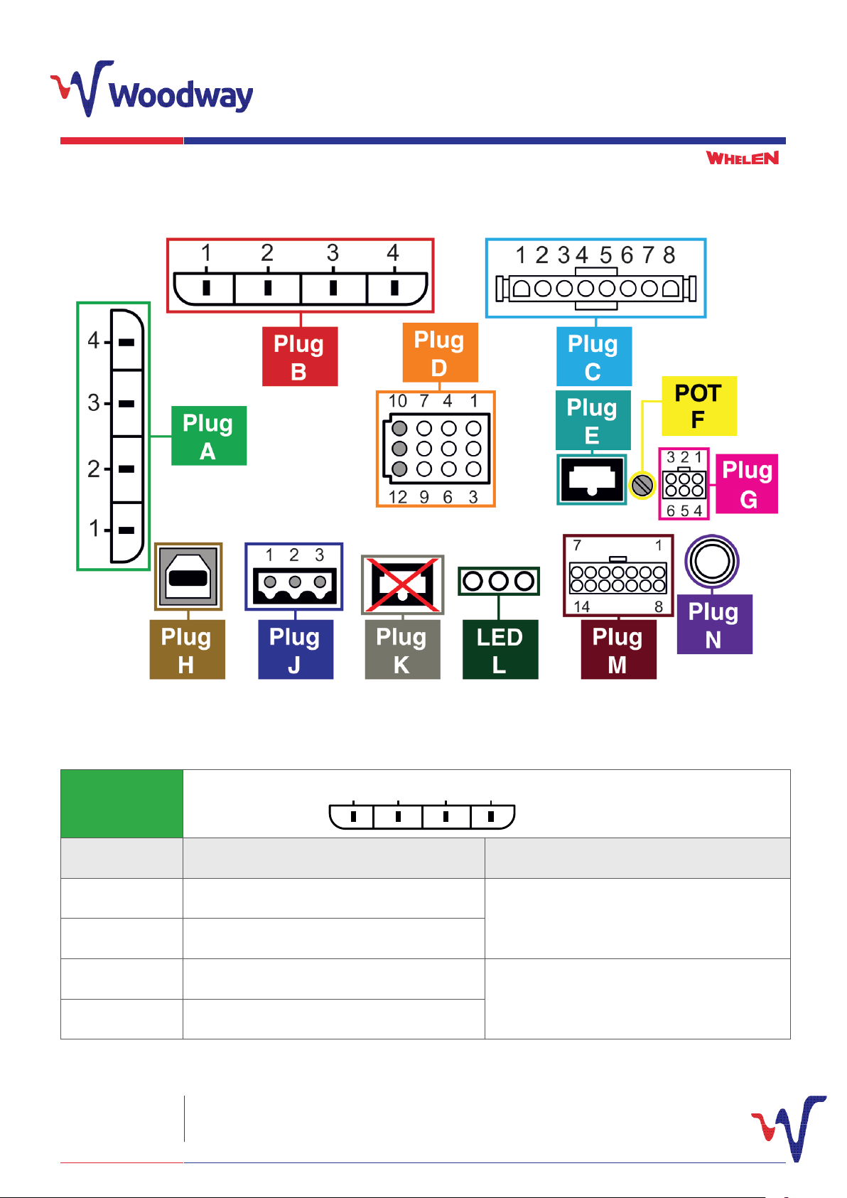
A Whelen WeCan® lightbar (Justice™ / Liberty™ / Legacy™ etc)
is the preferred choice to use with the CenCom Sapphire UK
for ease of tting and functionality. Connect your lightheads
and your lightbar to the CenCom Sapphire™ UK as per the
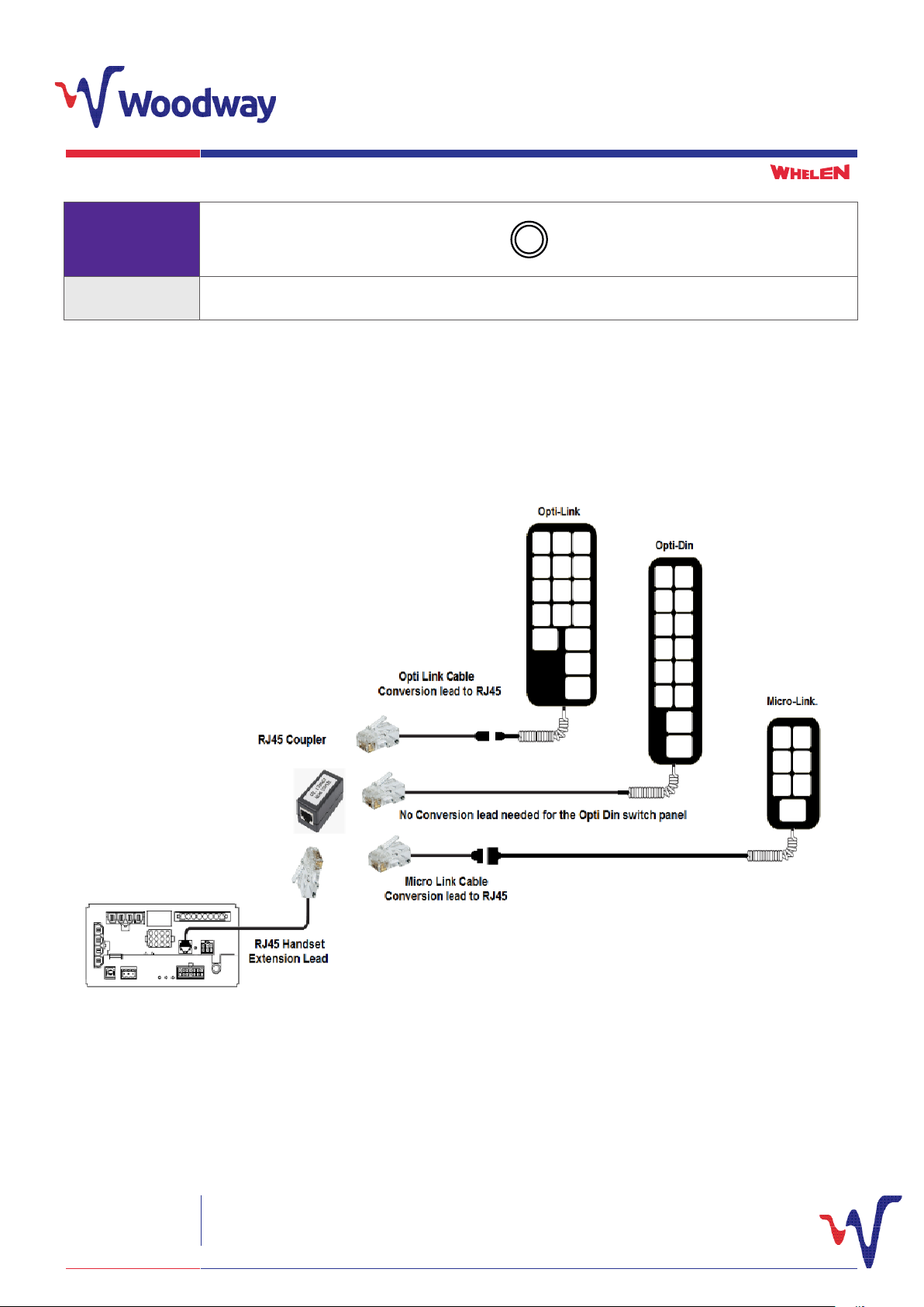
connection tables overleaf. Using the software provided
congure your chosen switch panel to switch each outlet.
For more information on installing the CenCom
Sapphire™ UK, visit the Woodway Engineering website.
You should always remember to use the appropriate rated fuse
for each individual load circuit, and never purposely overload any
circuit as this may cause damage to the CenCom Sapphire™ UK
and void the warranty.
The fuses shown are the maximum allowed for each circuit,
and must only be replaced with either the same rated fuse or
a smaller rated fuse. If a fuse blows, check for short circuits and
the load requirement for that circuit. Never insert a larger rated
fuse than that specied.
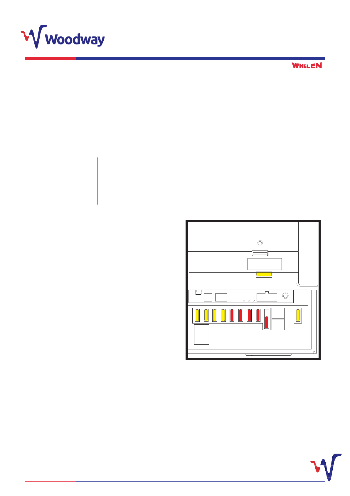
CenCom Sapphire UK - Fuses
LIGHTBAR
A022TUPTUO
A02
PNIAM
A02
A023TUPTUO
A014TUPTUO
A015TUPTUO
A016TUPTUO
A017TUPTUO
A02ESUFLO/GEN
8TUPTUO
A01
OUTPUT
10A
POSITION
DRY
CONTACT
POSITION
OUTPUT 1
40A
ERR
H S
USB L
PA
WC POW SYSTEM
I/O
-02-
-02-
-02-
-02-
-02-
-01-
-01-
-01-
-01-
-01-
Top
View
20A
SIRE N FUSE
- 20 -
Front
View

Woodway Engineering Ltd
Lower Road, Barnacle
Coventry, CV7 9LD
United Kingdom
Tel: +44 (0) 24 76 841750
Fax: +44 (0) 24 76 621796
www.woodwayengineering.com INSTALLATION GUIDE
4
®�
Plug Connection Labels
PLUG A
1 2 3 4
Pin Number Description Connection
1Main Earth
Vehicle Chassis Ground
2Main Earth
3Main CenCom 12V Input Vehicle or Auxiliary Battery Live. Fuse according to
load.
4Main CenCom 12V Input
Full Size Connector Diagram

Woodway Engineering Ltd
Lower Road, Barnacle
Coventry, CV7 9LD
United Kingdom
Tel: +44 (0) 24 76 841750
Fax: +44 (0) 24 76 621796
www.woodwayengineering.com INSTALLATION GUIDE
5
®�
PLUG B
1 2 3 4
Pin Number Description Connection
1
Output 1
Power Sockets
2Radios
3Output 2 Grille LEDs
4Output 3 Output to Headlight Flash Module Open
PLUG C
12345678
Pin Number Description Connection
1Output 4 Vehicle Tail Light / Rear Blues
2Output 5 Vehicle Tail Light / Rear Reds
3Output 6 (Positive Run Lock)
Run Lock
4Output 7 (Positive Run Lock)
5No Connection No Connection
6Output 8 (Contact Relay - Common) STVRU - Input from siren driver
7Output 8 (Contact Relay - Normally Closed) STVRU - Output from siren driver
8Output 8 (Contact Relay - Normally Open) Not used if using STVRU

Woodway Engineering Ltd
Lower Road, Barnacle
Coventry, CV7 9LD
United Kingdom
Tel: +44 (0) 24 76 841750
Fax: +44 (0) 24 76 621796
www.woodwayengineering.com INSTALLATION GUIDE
6
®�
PLUG D
10 7 4 1
12 9 6
3
Pin Number Description Connection
1N1 Output – Switched Negative
2N2 Output – Switched Negative
3N3 Output – Switched Negative
4N4 Output – Switched Negative Tailgate Blue LEDs
5N5 Output – Switched Negative Tailgate Red LEDs
6N6 Output – Switched Negative
7N7 Output – Switched Negative
8N8 Output – Switched Negative
9Solid 12 Volt Outputs Tailgate LEDs and Tilt Switch
10 Optional Headlight ash connection if applied (Optional) Flash Output to headlight – Switched Live
11 (Optional) Input power to Headlight asher – can
be supplied by Output 3 of CenCom
Switched Live to internal standalone headlight
asher if specied
12 Optional Headlight ash connection if applied (Optional) Flash Output to headlight – Switched Live
PLUG E
Description Switch Panel Connection
ADJUSTING
POT F
Description PA Volume Adjustment

Woodway Engineering Ltd
Lower Road, Barnacle
Coventry, CV7 9LD
United Kingdom
Tel: +44 (0) 24 76 841750
Fax: +44 (0) 24 76 621796
www.woodwayengineering.com INSTALLATION GUIDE
7
®�
PLUG G
3 2 1
6 5 4
Pin Number Description Suggestion
1Input 5 - Positive Foot Brake Input
2Input 6 - Positive
3Input 7 - Positive Remote EXT 999 activation
4Input 8 - Negative
5Input 9 - Negative
6Input 10 - Negative Remote Air Horn activation
PLUG H
Description PC Programming Port via USB
PLUG K
Description USA Switch Panel Connection Only
PLUG J
1 2 3
Pin Number Description
1WeCan® High, Green. Lightbar connection
2WeCan® Shield. Lightbar connection
3WeCan® Low, Grey. Lightbar connection

Woodway Engineering Ltd
Lower Road, Barnacle
Coventry, CV7 9LD
United Kingdom
Tel: +44 (0) 24 76 841750
Fax: +44 (0) 24 76 621796
www.woodwayengineering.com INSTALLATION GUIDE
8
®�
LED L
LED Number Description
1Used for US Specication Switch Panels
2Data Bus with WC lightbar LED
3Power Status LED
PLUG M
17
814
Pin Number Description
1Logic Input 1 - Positive / Negative Handbrake
2Logic Input 3 - Positive / Negative Ext output delay Timer enable
3Output 10 - 250mA Positive
4Output 9 - 250mA Positive (Siren In Use)
5Radio Repeat Input
6Siren Speakers Live Siren Drivers Positive
7No Connection
8Logic Input 2 - Positive / Negative Tailgate Tilt switch
9Logic Input 4 Horn Ring
10 Output 11 - 250mA Positive
11 Output 12 - 250mA Positive Horn Transfer Positive
12 Radio Repeat Input
13 Siren Speakers - Return Siren Drivers Negative
14 Ignition Input – 12V DC Positive Ignition Input – 12V DC Positive

Woodway Engineering Ltd
Lower Road, Barnacle
Coventry, CV7 9LD
United Kingdom
Tel: +44 (0) 24 76 841750
Fax: +44 (0) 24 76 621796
www.woodwayengineering.com INSTALLATION GUIDE
9
®�
PLUG N
Description Stand Alone Fist Microphone Socket
Switch Panel Connection Options
Once decided on which switch panel to use with the CenCom Sapphire UK, connect this up as shown below using the appropriate
supplied adaptor, which is only required with the Opti-Link and Micro-Link switch panels. The switch panel extension cable is plugged
in to socket ‘E’ of the CenCom Sapphire™ UK. The tail end of the extension cable will plug in to the RJ45 Coupler as shown below.

Woodway Engineering Ltd
Lower Road, Barnacle
Coventry, CV7 9LD
United Kingdom
Tel: +44 (0) 24 76 841750
Fax: +44 (0) 24 76 621796
www.woodwayengineering.com INSTALLATION GUIDE
10
®�
WeCan® Connection
Mount the lightbar to the roof of the vehicle following the steps in the supplied lightbar Installation Guide.
The CenCom Sapphire™ UK is focused towards the use of any lightbar from the WeCAN™ range.
1 2 3 4
4
3
2
1
3
1 2 3 4 567 8
10 7 4
2 1
12 9 6
3
21
6 5 4
3
1
17
814
To wire the lightbar to the CenCom Sapphire™ UK, connect the lightbars attached Red power wire to the battery’s ‘Positive’ (+) terminal
and the Black power wire to ‘Ground’ (-). Ensure that you install a fuse and that the correct rating for your tted lightbar (see lightbar
Installation instructions if unsure), is tted in line with your Red power wire as close to the battery terminal as possible. If wires need to
be extended, ensure that the wire used is correctly rated for the necessary current (recommended 125% of maximum current draw).
Run the Green (CAN High) and Grey (CAN Low) WeCan® wires to the CenCom Sapphire™ UK Using the supplied 3 Way WeCan®
screw terminal plug supplied. Using Ferrule crimps screw the wires into the 3 Way Plug using the following connections:
Pin 1 = GREEN CAN High
Pin 2 = SHIELD
Pin 3 = GREY CAN Low
With the three wires securely fastened into the 3 Way plug, it can then be connected to plug J of the CenCom Sapphire™ UK by rmly
mating the two connectors together.
The lightbar ash patterns can now be programmed using the supplied CenCom Sapphire™ UK programming software.

Woodway Engineering Ltd
Lower Road, Barnacle
Coventry, CV7 9LD
United Kingdom
Tel: +44 (0) 24 76 841750
Fax: +44 (0) 24 76 621796
www.woodwayengineering.com INSTALLATION GUIDE
11
Notes

Woodway Engineering Ltd
Lower Road, Barnacle
Coventry, CV7 9LD
United Kingdom
Tel: +44 (0) 24 76 841750
Fax: +44 (0) 24 76 621796
www.woodwayengineering.com
ISO 9001:2015 Certied 5 Year Warranty
Table of contents
Popular Automobile Accessories manuals by other brands

Cruz
Cruz Evo Rack E26-140 Assembly instructions

Boyo
Boyo VTB100TJ product manual

Steinhof
Steinhof M-031 FITTING AND OPERATION MANUAL

Enthuze Automotive
Enthuze Automotive ENT4084 quick start guide

Metra Electronics
Metra Electronics 99-8157B installation instructions

PNEUMATIC
PNEUMATIC KU-MI-AX00-00 Installation instruction