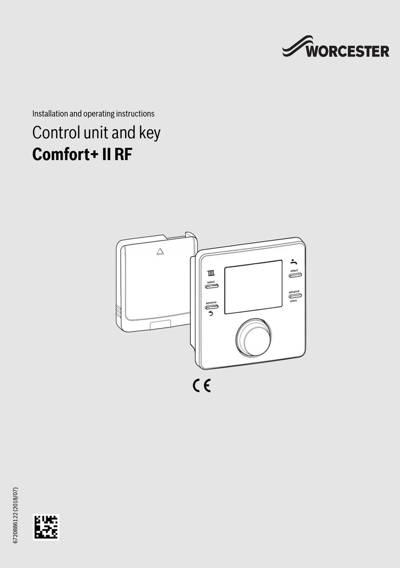
Worcester Comfort+ I RF/Stat RF User manual

6720886119 (2018/07)
Installation and operating instructions
Control unit and key
Comfort+ I RF/Stat RF

Table of contents
Comfort+ I RF/Stat RF – 6720886119 (2018/07)
2
Table of contents 1 Explanation of symbols and safety
instructions
1.1 Explanation of symbols
Warnings
In warnings, signal words at the beginning of a warning are used
to indicate the type and seriousness of the ensuing risk if
measures for minimising danger are not taken.
The following signal words are defined and can be used in this
document:
DANGER:
DANGER indicates that severe or life-threatening personal
injury will occur.
WARNING:
WARNING indicates that severe to life-threatening personal
injury may occur.
CAUTION:
CAUTION indicates that minor to medium personal injury may
occur.
NOTICE:
NOTICE indicates that material damage may occur.
Important information
The info symbol indicates important information where there is
no risk to people or property.
1 Explanation of symbols and safety instructions . . . . . 2
1.1 Explanation of symbols . . . . . . . . . . . . . . . . . . . . . . 2
1.2 General safety instructions . . . . . . . . . . . . . . . . . . . 3
2 Product Information . . . . . . . . . . . . . . . . . . . . . . . . . . . . 3
2.1 Function as room temperature-dependent
controller . . . . . . . . . . . . . . . . . . . . . . . . . . . . . . . . . 3
2.2 User interface. . . . . . . . . . . . . . . . . . . . . . . . . . . . . . 4
2.2.1 Control unit . . . . . . . . . . . . . . . . . . . . . . . . . . . . . . . 4
2.2.2 Key . . . . . . . . . . . . . . . . . . . . . . . . . . . . . . . . . . . . . . 4
3 Installation and commissioning. . . . . . . . . . . . . . . . . . . 5
3.1 Installation . . . . . . . . . . . . . . . . . . . . . . . . . . . . . . . . 5
3.1.1 Installing the key . . . . . . . . . . . . . . . . . . . . . . . . . . . 5
3.1.2 Putting the control unit into operation . . . . . . . . . . 5
3.1.3 Installing Comfort+ I RF/Stat RF control unit. . . . . 6
3.2 Start-up after a reset . . . . . . . . . . . . . . . . . . . . . . . . 7
4 Using the control unit . . . . . . . . . . . . . . . . . . . . . . . . . . . 7
5 Settings in the service menu . . . . . . . . . . . . . . . . . . . . . 7
6 Troubleshooting. . . . . . . . . . . . . . . . . . . . . . . . . . . . . . . . 8
6.1 Temperature faults. . . . . . . . . . . . . . . . . . . . . . . . . . 8
6.2 Faults in the control unit or key . . . . . . . . . . . . . . . . 8
6.2.1 User interface . . . . . . . . . . . . . . . . . . . . . . . . . . . . . 8
6.2.2 Key . . . . . . . . . . . . . . . . . . . . . . . . . . . . . . . . . . . . . . 8
7 Maintenance. . . . . . . . . . . . . . . . . . . . . . . . . . . . . . . . . . . 8
7.1 Replace batteries . . . . . . . . . . . . . . . . . . . . . . . . . . . 8
8 Product data for energy consumption . . . . . . . . . . . . . 9
9 Simplified EU Declaration of Conformity
regarding radio equipment. . . . . . . . . . . . . . . . . . . . . . . 9
10 Specifications. . . . . . . . . . . . . . . . . . . . . . . . . . . . . . . . . . 9
11 Environmental protection/disposal . . . . . . . . . . . . . . . 9

Product Information
3
Comfort+ I RF/Stat RF – 6720886119 (2018/07)
1.2 General safety instructions
Installation and commissioning
▶ Observe all country-specific regulations and standards
during installation and operation!
▶ All instructions must be observed. Failure to comply with
instructions may result in material damage and personal
injury, including possible loss of life.
▶ Ensure that the user interface is installed and
commissioned by an approved contractor.
▶ Do not install the user interface in wet areas.
▶ Install and commission the heat source and other
accessories in accordance with the relevant instructions.
▶ Never connect the user interface to the 230 V mains.
▶ Before installing the user interface: electrically isolate the
heat source and all other BUS units from the power supply
and secure against unintentional reconnection, making
sure that the power supply is completely disconnected.
HDamage caused by frost
The solar system can freeze if it is
switched off:
▶ Observe the notices regarding frost
protection.
▶ Due to the additional functions, e.g.
DHW heating or pump anti-seizure
protection, the system should always
be left on.
▶ Correct any faults immediately.
HElectrical work
Electrical work may be carried out only
by qualified electricians.
▶ Before starting electrical work:
– Isolate all poles of the mains
voltage and secure against
reconnection.
– Make sure the mains voltage is
disconnected.
▶ Never connect the product to the
mains voltage.
▶ Observe the wiring diagrams of other
system components as well.
2 Product Information
Possible applications and use
Comfort+ I RF activates the timer in the wall-mounted boiler
(operating instructions for the appliance).
• Use as room temperature-dependent controller for
systems with one unmixed heating circuit
• Use in the case of a heat source with BUS system, EMS 2
Supplied parts
• Control unit
•Key
• Technical documentation
• Batteries
2.1 Function as room temperature-dependent
controller
The Comfort+ I RF/Stat RF controls the heat source via the
room temperature. The control unit is not suitable for
controlling heat sources from other manufacturers.
Output control
The heat output of the heat source changes according to the
discrepancy between the current and desired room
temperature. This method of control is suitable for a uniform
temperature level, e.g. open-plan house. There are fewer
burner starts and shorter pump runtimes. This control mode
may not be available depending on the connected heat source.

Product Information
Comfort+ I RF/Stat RF – 6720886119 (2018/07)
4
2.2 User interface
2.2.1 Control unit
Fig. 1 Control elements
[1] Display
[2] Battery status indicator
[3] Burner ON Indicator
[4] Rotary push button knob: select (turn) and confirm
(press)
[5] Current room temperature
2.2.2 Key
The key must be used in conjunction with the control unit.
The key is installed in the heat source.
[1] Button on key
[2] LED on key
Description of the displays Example
Current room temperature (standard display)
Desired room temperature:
▶ Press selector to briefly show the desired
room temperature (flashing).
Battery status indicator:
Weak battery
▶ Replace batteries within 60 days.
Boiler is producing heat, e.g. the burner is running.
Setting the desired room temperature Result
▶ Turn the selector to select the desired room
temperature.
▶ Press the selector to confirm the setting.
Switching off the heating Result
▶ Reduce the desired room temperature, until
OFF appears. When the heating is switched
off, frost protection for the room is also
switched off. Frost protection of the heat
source remains active.
0 010 020 514-001
1
3
4
5
2
°C
°F
°C
°F
°C
°F
°C
°F
°C
°F
Description of the LED displays Example
Red flashing LED:
Fault, e.g. no EMS connection:
▶ Install the key again, restore the last
functioning status.
Flashing green:
No fault, initialisation process is running.
Constant red:
Temporary fault:
▶ Wait for normal operating condition to be
resumed.
Constant yellow LED:
No fault, time and date not available:
▶ Set the time and date on the appliance.
Constant green LED:
No fault, normal operating condition.
LED Off:
No fault, power-saving mode or appliance
switched off.
1 2
0010021545-002

Installation and commissioning
5
Comfort+ I RF/Stat RF – 6720886119 (2018/07)
3 Installation and commissioning
3.1 Installation
CAUTION:
Electrical work
Electrical work must only be carried out by a qualified
electrician.
▶ Before starting electrical work:
Isolate the mains electrical supply and secure against
unintentional re-connection.
▶ Check for zero voltage.
▶ Also observe connection diagrams of other system
components.
For information on the heat source, Technical
documentation for the heat source.
These instructions contain the installation and operating
instructions for the Comfort+ I RF/Stat RF control unit.
3.1.1 Installing the key
▶ Isolate the mains electrical supply and secure against
unintentional re-connection.
▶ Install the key in the heat source. For information in
installing in the heat source, Technical documentation
for the heat source.
Fig. 2 Installing the key
▶ Switch on the heat source.
Fig. 3 Initialisation
▶ Set time and date. For information on setting timer and
date, Technical documentation for the heat source.
Fig. 4 Setting time and date
3.1.2 Putting the control unit into operation
The control unit and key are paired in the factory at the time of
manufacture. They detect each other automatically when
switching on.
▶ Insert the batteries in the control unit (sec 7.1, page 8).
▶ The key and control unit connect automatically.
While the connection is being established, the control unit
shows a countdown starting with 120.
Once installed the display shows the current room temperature
after the connection has been established.
▶ Ensure that the signal strength is adequate at the
installation location for the control unit, before you install it
(page 7).
▶ Install the control unit.
0010022807-001
1. 2.
0010022813-001
yellow
2. 3.1.
0010022808-001
1.
00:00 DD/MM/YYYY
green
2.

Installation and commissioning
Comfort+ I RF/Stat RF – 6720886119 (2018/07)
6
3.1.3 Installing Comfort+ I RF/Stat RF control unit
Fig. 5 Installation location of the control unit
Fig. 6 Wireless range
Releasing control unit from wall socket
Fig. 7 Releasing control unit from wall socket
Wall-mounted installation
Find a position with good signal strength before starting the
wall-mounted installation of the control unit.
If the signal strength is low, check out another position in the
room, until the best possible signal strength is achieved
(page 7).
▶ Use the wall socket as a template to mark the position of the
screws.
▶ Drill two suitable holes for the length and diameter of the
rawl plugs.
Fig. 8 Installing the wall socket for the control unit
▶ Insert the rawl plugs.
▶ Insert the screws in such a way, that they protrude
sufficiently to enable the wall socket to fit behind the screw
heads.
▶ Install the wall socket horizontally.
°C
°F
750
≥ 1000
≥ 1200
750
600
°C
°F
500
0010021101-001
°C
°F
°C
°F
°C
°F
0010021103-002
1.
3.
0 010 020 505-001
2.
6720810965-08.1Wo

Using the control unit
7
Comfort+ I RF/Stat RF – 6720886119 (2018/07)
3.2 Start-up after a reset
4 Using the control unit
Operations with examples.
The control unit and key are connected in the factory at the time
of manufacture and detect each other automatically, as soon as
the key is installed and connect when the system is switched
on. There is no need to pair/unpair the units during installation,
unless there is a problem with one or both of the units.
5 Settings in the service menu
A reset restores the default setting. The settings are retained in
the event of a power failure.
Systems with one heating circuit (room controller – CO)
▶ Switch on the system / Reset Comfort+ I RF/
Stat RF.
Three dashes are displayed while the
connection is being established. The room
temperature is displayed after the connection
has been established.
Opening the service menu Result
▶ Press and hold the selector until 2 dashes are
displayed.
▶ Release the selector to display the first setting.
Connecting with other appliances Result
▶ Select a setting in the service menu.
▶ Turn the selector to connect the key and
control unit.
▶ Press the selector to start the connection.
During connection a countdown starts at
120 s. As soon as a connection is established,
the countdown is ended and 1 flashes for 3 s.
The appliances are connected. Menu rF 1 then
opens.
▶ If the countdown is on 0 s and no connection
has been established, the display changes
again to A.
▶ After 30 s the current room temperature is
displayed, or press and hold the selector for
more than 3 s to return to the previous menu.
▶ Close the service menu.
Checking the signal strength Result
▶ Select a setting in the service menu.
▶ Press the selector.
▶ The signal strength is displayed as a number
from 0 to 10.
[0] No reception
[1-3] Poor reception
[4-6] Good reception
[7-10] Very good reception
▶ Close the service menu.
°C
°F
°C
°F
°C
°F
°C
°F
°C
°F
°C
°F
°C
°F
Closing the service menu Result
▶ Press and hold the selector until 3 dashes are
displayed.
▶ Release the selector.
The current room temperature is displayed
and the control unit operates with the changed
setting.
Setting Adjustment
range1)
1) Highlighted values = Default setting
Description
S2 Signal strength
rF 1 Connection between control unit
and key
S1 Software version2)
2) Turn the selector to read out the whole value.
F1 1 | 0Resetting Stat RF/Comfort+ I RF
0: Do not reset
1: Reset
E1 – 3.0 ... 0.0
... 3.0
Correction value for the room
temperature displayed
°C
°F
°C
°F

Troubleshooting
Comfort+ I RF/Stat RF – 6720886119 (2018/07)
8
6 Troubleshooting
If a fault can not be rectified, note down the fault code:
▶ Contact the approved contractor or Customer Service.
▶ Advise the type of fault and ID no. of the control unit.
Table 1 ID no. rear of the control unit (to be entered by the
installer)
If there is a fault, the display shows the fault code.
If further information required, see the service manual.
6.1 Temperature faults
Table 2
6.2 Faults in the control unit or key
6.2.1 User interface
In the event of a fault, a fault code is displayed.
Table 3 Fault codes for the specialist
6.2.2 Key
Table 4
7 Maintenance
7.1 Replace batteries
The control unit and key require no maintenance other than
changing the batteries in the control unit.
The casing can be cleaned with a dry cloth. Do not use cleaning
agents or solutions.
The control unit is powered by 2 AAA batteries.
As soon as the symbol for weak batteries is displayed in normal
operation, the batteries must be replaced within the next
60 days, otherwise the programmed settings are lost.
Access to the batteries
To release the control unit from the wall socket:
1. Insert a flat-head screwdriver into the recess on the
underside of the control unit.
2. Gently turn the screwdriver, until the locking device is
open.
3. Release the control unit from the wall socket (fig. 7,
page 6).
Replace batteries
▶ Replace the used batteries with new ones of the same
type (AAA).
▶ Ensure that the +pole of the battery is inserted in the
+pole of the battery compartment.
▶ Fit the control unit into the wall socket: first insert into the
lugs [1] at the top and then latch the underside into place.
CAUTION:
Risk of explosion if the battery is replaced with an incorrect
type.
▶ Use specified batteries only.
__ _
[Desired room temperature is exceeded]
Test procedure/cause Action
Check the installation
locationof the control unit (
fig. 5)
Install the control unit in a
better place.
Fault
code
Possible cause and
remedy from the specialist
A61 No wireless signal
▶ Check the signal strength and position the control
unit in a better place.
A91 No communication via EMS (reported by the heat
source)
▶ Check EMS connection.
▶ Check that the key is installed correctly.
A91 The control unit is not connected to a heat source
(established by the control unit)
▶ Check EMS connection.
▶ Check that the key is installed correctly.
A01 "Maintenance due" triggered by the Landlord function
(reported by the heat source)
A11 For all other fault codes, which the heat source reports
[LED flashes red once per second]
Description Action
Local program fault
No fault in the heat source but
probably loss of the wireless
signal to at least one control
unit.
Check the control units for
faults.

Product data for energy consumption
9
Comfort+ I RF/Stat RF – 6720886119 (2018/07)
Fig. 9 Replace batteries
8 Product data for energy consumption
The product data specified comply with the requirements of
EURegulation No. 811/2013 as a supplement to
EcodesignDirective 2017/1369/EU. The class of temperature
controller is required to calculate the central heating energy
efficiency of an integrated system, and it is therefore
incorporated into the system data sheet.
1) Classification in accordance with EU Regulation No. 811/
2013 for identification of integrated systems
2) Contribution to seasonal energy efficiency of central
heating in %
9 Simplified EU Declaration of Conformity
regarding radio equipment
Bosch Thermotechnik GmbH hereby declares, that the
Comfort+ I RF/Stat RF product described in these instructions
complies with the Directive 2014/53/EU.
The complete text of the EU Declaration of Conformity is
available on the Internet: worcester-bosch.co.uk.
10 Specifications
Table 5 Wireless technology in Comfort+ I RF/Stat RF
Table 6
11 Environmental protection/disposal
Used electrical and electronic appliances
Electrical or electronic devices that are no longer
serviceable must be collected separately and sent
for environmentally compatible recycling (in
accordance with the European Waste Electrical
and Electronic Equipment Directive).
To dispose of old electrical or electronic devices, you should
use the return and collection systems put in place in the country
concerned.
Batteries must not be disposed together with your household
waste. Used batteries must be disposed of in local collection
systems.
Function of Comfort+ I RF/Stat RF
& key
Class1) [%]1),2)
Room temperature-dependent,
modulating
V 3.0
0 010 020 506-001
+
+
1
Band width frequency 868.7 ... 869.2 MHz
Maximum transmitting capacity <10 mW
Transmission frequency 868 MHz
Transmission protocol (wireless) X3D-C
Receiver category 2
Dimensions (W × H × D) 82 × 82 × 23 mm
Power supply 2 × AAA
Battery service life in normal use 2 years
Rated current 12 mA
BUS interface EMS 2
Control range 5 ... 30 °C
Permissible ambient temperature 0 ... 60 °C
Protection class III
IP rating IP20
Temperature of ball test 75 °C
Degree of pollution 2


Bosch Thermotechnology Ltd.
Cotswold Way, Warndon
Worcester WR4 9SW
United Kingdom
Tel. 0330 123 9559
worcester-bosch.co.uk
TECHNICAL SUPPORT: 0330 123 3366
RENEWABLE SUPPORT: 0330 123 9229
CONTROLS AND CONNECTIVITY TEAM: 0330 123 3641
APPOINTMENTS: 0330 123 9339
SPARES: 0330 123 9779
LITERATURE: 0330 123 9119
TRAINING: 0330 123 0166
SALES: 0330 123 9669
Table of contents
Other Worcester Control Unit manuals
Popular Control Unit manuals by other brands

Fuji Electric
Fuji Electric MT5F33743 manual

Cabletron Systems
Cabletron Systems TRMM user guide

Cosel
Cosel CHS12024 instruction manual

Nielsen-Kellerman
Nielsen-Kellerman COX-BOX PLUS SYSTEM INSTALLATION, MAINTENANCE AND TROUBLESHOOTING GUIDE

MSA
MSA Chillgard LC instruction manual

HIOS
HIOS CB-105 Operation manual