Worcester Comfort+ II RF User manual

6720892636 (2019/04) GB
Installation and user manual
Control unit and Key
Comfort+ II RF
select
advance
select
advance
menu

Table of contents
Comfort+ II RF – 6720892636 (2019/04)
2
Table of contents
1 Explanation of symbols and safety instructions . . . . . 3
1.1 Explanation of symbols . . . . . . . . . . . . . . . . . . . . . . 3
1.2 General safety instructions . . . . . . . . . . . . . . . . . . . 3
2 About the product . . . . . . . . . . . . . . . . . . . . . . . . . . . . . . 4
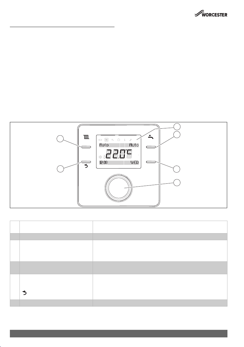
2.1 User interface. . . . . . . . . . . . . . . . . . . . . . . . . . . . . . 4
2.2 Key . . . . . . . . . . . . . . . . . . . . . . . . . . . . . . . . . . . . . . 5
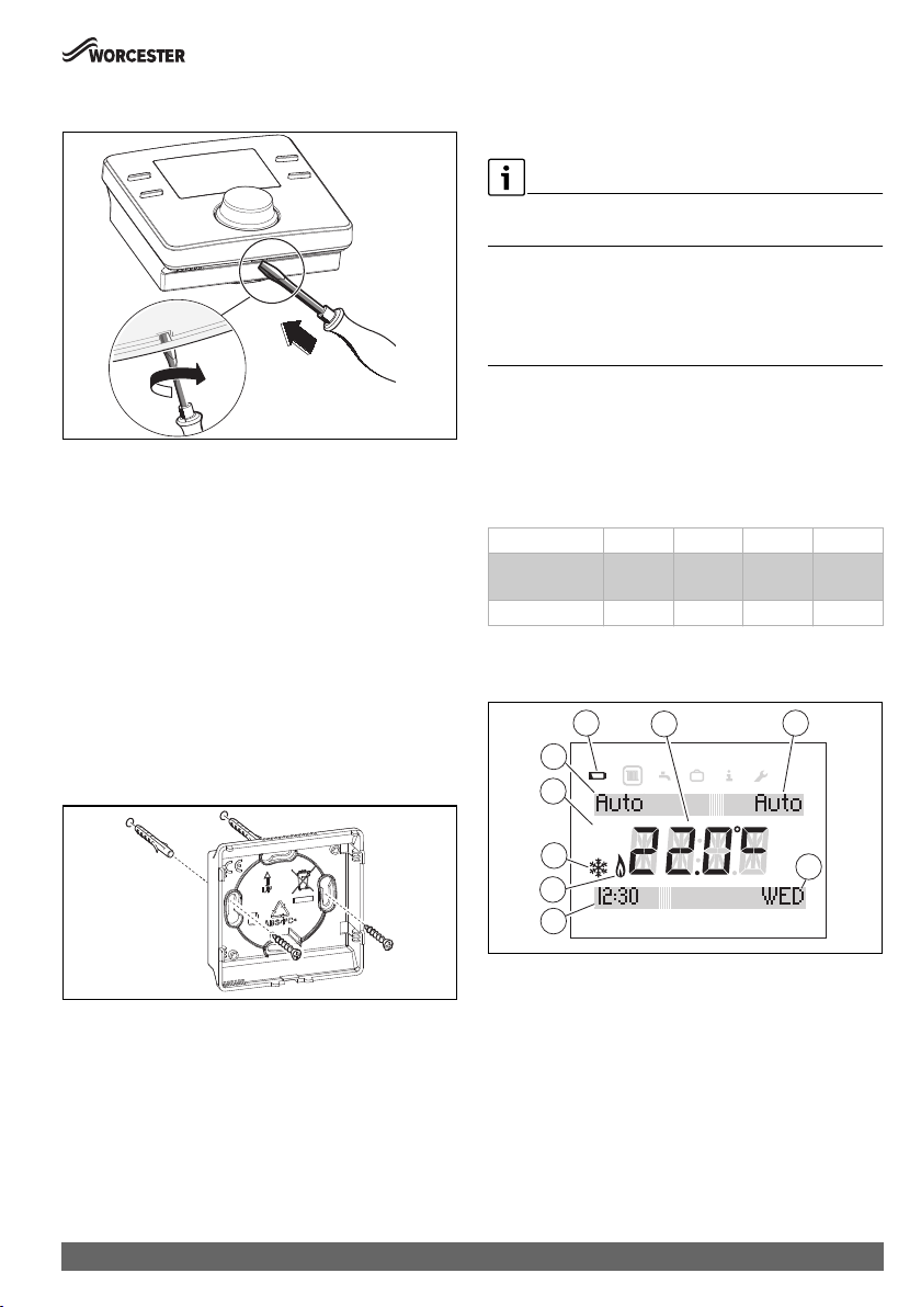
3 Installation and commissioning. . . . . . . . . . . . . . . . . . . 5
3.1 Installation and commissioning key . . . . . . . . . . . . 5
3.2 Installation and commissioning of the control
unit . . . . . . . . . . . . . . . . . . . . . . . . . . . . . . . . . . . . . . 6
3.3 Putting the control unit into operation . . . . . . . . . . 7
4 Using the control unit . . . . . . . . . . . . . . . . . . . . . . . . . . . 7
4.1 Standard display . . . . . . . . . . . . . . . . . . . . . . . . . . . 7
4.2 Call up/select temperature setting of
operating modes . . . . . . . . . . . . . . . . . . . . . . . . . . . 8
4.2.1 Room temperature display of Auto operating
mode. . . . . . . . . . . . . . . . . . . . . . . . . . . . . . . . . . . . . 8
4.2.2 Room temperature display of On operating
mode. . . . . . . . . . . . . . . . . . . . . . . . . . . . . . . . . . . . . 8
4.2.3 Room temperature display of Off operating
mode. . . . . . . . . . . . . . . . . . . . . . . . . . . . . . . . . . . . . 8
4.2.4 Setting the room temperature . . . . . . . . . . . . . . . . 8
4.3 Key lock. . . . . . . . . . . . . . . . . . . . . . . . . . . . . . . . . . . 8
5 Settings in the main menu . . . . . . . . . . . . . . . . . . . . . . . 9
5.1 Time program for adjusting the heating . . . . . . . . . 9
5.2 Setting the DHW time program . . . . . . . . . . . . . . . 10
5.3 Deactivate switching times . . . . . . . . . . . . . . . . . . 10
5.4 Reset time program . . . . . . . . . . . . . . . . . . . . . . . . 10
5.5 Setting the temperature . . . . . . . . . . . . . . . . . . . . 11
5.6 Holiday . . . . . . . . . . . . . . . . . . . . . . . . . . . . . . . . . . 11
5.7 Information. . . . . . . . . . . . . . . . . . . . . . . . . . . . . . . 11
5.8 Adjust . . . . . . . . . . . . . . . . . . . . . . . . . . . . . . . . . . . 12
6 Settings in the service menu . . . . . . . . . . . . . . . . . . . . 13
6.1 System data . . . . . . . . . . . . . . . . . . . . . . . . . . . . . . 13
6.2 Restoring the factory settings (Reset all) . . . . . . . 14
6.3 Heat.circuit. . . . . . . . . . . . . . . . . . . . . . . . . . . . . . . 14
6.4 Maintenance. . . . . . . . . . . . . . . . . . . . . . . . . . . . . . 14
6.5 System info. . . . . . . . . . . . . . . . . . . . . . . . . . . . . . . 15
6.6 Radio settings - connecting/disconnecting . . . . . 15
6.7 Heating curve settings . . . . . . . . . . . . . . . . . . . . . . 15
7 Key . . . . . . . . . . . . . . . . . . . . . . . . . . . . . . . . . . . . . . . . . . 17
7.1 outside temperature sensor or new control
unit . . . . . . . . . . . . . . . . . . . . . . . . . . . . . . . . . . . . . 17
7.2 Factory reset Key . . . . . . . . . . . . . . . . . . . . . . . . . . 18
8 Troubleshooting . . . . . . . . . . . . . . . . . . . . . . . . . . . . . . . 18
8.1 Troubleshooting . . . . . . . . . . . . . . . . . . . . . . . . . . . 18
9 Maintenance. . . . . . . . . . . . . . . . . . . . . . . . . . . . . . . . . . 19
9.1 Replace batteries of control unit. . . . . . . . . . . . . . 19
10 Product data for energy consumption . . . . . . . . . . . . 20
11 Simplified EU Declaration of Conformity
regarding radio equipment . . . . . . . . . . . . . . . . . . . . . 20
12 Specifications. . . . . . . . . . . . . . . . . . . . . . . . . . . . . . . . . 20
13 Environmental protection/disposal . . . . . . . . . . . . . . 20
14 Overview of main menu . . . . . . . . . . . . . . . . . . . . . . . . 21

Explanation of symbols and safety instructions
3
Comfort+ II RF – 6720892636 (2019/04)
1 Explanation of symbols and safety
instructions
1.1 Explanation of symbols
Warnings
In warnings, signal words at the beginning of a warning are used
to indicate the type and seriousness of the ensuing risk if
measures for minimising danger are not taken.
The following signal words are defined and can be used in this
document:
DANGER:
DANGER indicates that severe or life-threatening personal
injury will occur.
WARNING:
WARNING indicates that severe to life-threatening personal
injury may occur.
CAUTION:
CAUTION indicates that minor to medium personal injury may
occur.
NOTICE:
NOTICE indicates that material damage may occur.
Important information
The info symbol indicates important information where there is
no risk to people or property.
1.2 General safety instructions
HNotices for the target group
These operating instructions are
intended for the heating system
operator.
All instructions must be observed.
Failure to comply with instructions may
result in material damage and personal
injury, including danger to life.
▶ Read and retain the operating
instructions (heat source, heating
controller, etc.) prior to operation.
▶ Observe the safety instructions and
warnings.
HDetermined use
▶ Use the product only to control
heating systems.
Any other use is considered
inappropriate. We take no responsibility
for damage caused through incorrect use.
HRisk of scalding at the DHW draw-
off points
▶ If DHW temperatures above 60 °C are
set or if thermal disinfection is
activated, a mixer must be installed.
If in doubt, ask your installer.

About the product
Comfort+ II RF – 6720892636 (2019/04)
4
2 About the product
The Comfort+ II RF contains the programmable, wall mounted
control unit Comfort+ II RF for the radio-controlled remote
control and the Key which is implemented in the heat source.
2.1 User interface
The control unit is a room temperature-dependent controller.
The control unit can be used together with an outside
temperature sensor (wireless or tethered) as a weather-
compensated wireless controller. The purpose of the control
unit is to control a heating system via radio remote control and
it is mounted on the wall. The control unit is suitable for central
heating and DHW heating via a heating controller with
modulation. Up to six switching times can be set in the central
heating and DHW program.
The modulation facilitates intelligent communication with the
heat source so the required room temperature is obtained as
efficiently as possible. The burner may stop shortly before the
required room temperature is reached in order to save fuel/
money and minimise the extent to which the required room
temperature is exceeded. This behaviour, together with lower
radiator temperatures, is normal. The required room
temperature must only be set once at the control unit. Open the
thermostatic valves at the radiators in the room in which the
control unit is used completely and set the output of the
radiators as low as possible via adjustable lockshield valves or
set the manual valves as low as possible.
All programming and adjustment can be carried out
conveniently from the living space which means the
Comfort+ II RF is the perfect choice for heat sources that are
difficult to access.
Fig. 1 User interface
Table 1
select
advance
select
advance
menu
pmam
6
5
1
2
3
4
0010009727
1 display Temperature, time, date, heating (CH) and domestic hot water (DHW),
fault code, menu symbols and symbols
2 DHW key On, Off, Auto, Once, Adv
3 Advance key
Menu key
Single press - timer moves further to the next programmed power-up or
shutdown time. Repeated press – timer returns to the original program.
Long press – main menu is opened.
4Rotary push button knob: select (turn) and
confirm (press)
Select (turn), confirm (press), exit the idle state (press briefly) and switch on
the display illumination (press for longer than one second)
5 Advance key
key
Single press – temperature of the next switching time applies as a set
temperature immediately. Repeated press – timer returns to the original
program.
Single press (navigation in the menu) – timer returns to superordinate menu.
6 Heat key On, Off, Auto, Adv

Installation and commissioning
5
Comfort+ II RF – 6720892636 (2019/04)
2.2 Key
The Key is used together with the control unit.
The Key is installed in the heat source.
Fig. 2 Key
[1] Connect the Key
[2] LED on the Key
3 Installation and commissioning
CAUTION:
Electrical work
Electrical work must only be carried out by a qualified
electrician.
▶ Before starting electrical work:
Isolate the mains electrical supply and secure against
unintentional re-connection.
▶ Check for zero voltage.
▶ Also observe connection diagrams of other system
components.
For information on the heat source,
Technical documentation for the heat source.
These instructions contain the installation and operating
instructions for the Comfort+ II RF control unit.
3.1 Installation and commissioning key
Installation in the heat source
▶ Isolate the mains electrical supply and secure against
unintentional reconnection.
▶ Install Key in the heat source. For wall mounted gas boilers,
through insertion into the key slot from below.
For information on the installation in the heat source
technical documentation of the heat source.
Fig. 3 Install Key
Description of the LED displays Example
Red flashing LED:
Fault, e.g. no EMS connection:
▶ Install Key again, reproduce last functional
state.
Yellow flashing:
Pairing-mode, new/additional wireless participant
can be registered.
Flashing green:
No fault, initialisation process is running.
Constant red:
Temporary fault, e.g. no wireless participant
within range:
▶ Wait for normal operating condition to be
resumed.
Constant yellow LED:
No fault, no wireless participant registered/
connected on the key:
▶ Separate control unit and then reconnect
with key (Chapter 6.6, page 15).
Constant green LED:
No fault, normal operating condition.
LED Off:
No fault, power-saving mode or appliance
switched off.
1 2
0010021545-002
0010022807-002
1. 2.

Installation and commissioning
Comfort+ II RF – 6720892636 (2019/04)
6
▶ Switch on the heat source.
Fig. 4 Initialisation
Control unit and Key are connected in delivered condition ex
factory and detect each other automatically when powered up.
▶ Insert batteries into the control unit (Chapter
9
, page
19
).
▶ Key and control unit connect automatically.
Once installed, the display displays the current room
temperature after the connection has been established.
▶ Before the installation of the control unit, ensure that the
signal strength at the installation location of the control unit
is sufficient (section "Signal strength", page 11).
▶ Install the control unit.
3.2 Installation and commissioning of the
control unit
Putting the control unit into operation
The control unit uses wireless frequencies. It therefore offers
flexibility in terms of selecting a position. Connection of cables
is not required.
Air must be able to circulate freely round the control unit and it
must be installed on an open surface unhindered by curtains or
furniture. The control unit must not be positioned closer than
300 mm to metal objects, including wall-mounted metal boxes.
Do not mount the control unit on a wall where it will be exposed
to sunlight or draughts, preferably on an inside wall 1.2 m
above the floor.
The control unit must not be directly influenced by radiators or
heat-emitting objects, such as TVs or table lamps.
Fig. 5 Installation location of the control unit
Fig. 6 Wireless range
0010026081-001
2.1.
°C
°F
750
≥ 1000
≥ 1200
750
600
°C
°F
500
0010021101-001
°C
°F
°C
°F
°C
°F
0010021103-002

Using the control unit
7
Comfort+ II RF – 6720892636 (2019/04)
Releasing control unit from wall socket
Fig. 7 Releasing control unit from wall socket
▶ Insert a screwdriver into the recess on the underside of the
control unit.
▶ Gently turn the screwdriver, until the locking device opens.
Wall-mounted installation
Find a position with good signal strength before starting the
wall-mounted installation of the control unit.
If the signal is weak, try another position in the room, until the
best possible signal strength is achieved (Section "Signal
strength", page 11).
▶ Use the wall socket as a template to mark the position of the
screws.
▶ Drill two suitable holes for the length and diameter of the
rawl plugs.
Fig. 8 Installing the wall socket for the control unit
▶ Insert the rawl plugs.
▶ Insert the screws in such a way, that they protrude
sufficiently to enable the wall socket to fit behind the screw
heads.
▶ Install the wall socket horizontally.
3.3 Putting the control unit into operation
▶ Switch on the heat source.
Control unit and Key are set and connected ex factory so that
they are directly functional.
Once the connection has been established, the preset date and
time, the heating and DHW Auto mode and the current room
temperature will appear on the display.
4 Using the control unit
The control unit has preset heating and DHW switching times
(Table 2). These settings can be adjusted to meet the
requirements of the user in the menu (Chapter 5, page 9).
The switching times can be reset to factory settings
(section "Reset to factory settings (Reset all)", page 11).
Table 2
4.1 Standard display
Fig. 9 Standard display
[1] Current room temperature
[2] DHW operating mode
[3] Day of the week
[4] Clock
[5] Burner in operation (lights up if heat source is in heating
mode; up to 6-minute delay)
[6] Frost protection (lights up in heating mode Off)
[7] am or pm (lights up if 12-hour time format is used)
[8] Heating operating mode
[9] Battery low
0 010 010 085-001
2.
1.
6720810965-08.1Wo
Switching time 06:30 08:30 16:30 22:30
Heating
temperature
20 °C 16 °C 21 °C 10 °C
Hot water On Off On Off
0010009667-002
12
3
4
8
7
6
5
9
pmam

Using the control unit
Comfort+ II RF – 6720892636 (2019/04)
8
•Pressselect key for heating program to select one of the
following operating modes:
–On = heating is permanently on
–Off = heating is permanently off
–Auto = programmed switching times are executed
–Adv = select/deselect heating program in the Auto
operating mode by pressing the advance key to bring
the next programmed switching time forward or to
revert to the normal program.
•Pressselect key to select one of the following operating
modes:
–On = DHW heating permanently on
–Off = DHW heating permanently off
–Once = DHW heating on, from the first programmed
switch-on time to the last programmed switch-off time
–Auto = programmed switching times are executed
–Adv = select/deselect DHW program in the Auto
operating mode by pressing the advance key to bring
the next programmed switching time forward or to
revert to the normal program.
4.2 Call up/select temperature setting of
operating modes
4.2.1 Room temperature display of Auto operating mode
If the control unit is in the operating mode Auto, press the
selector to display the setpoint value of the room temperature.
Fig. 10 Automatic heating
4.2.2 Room temperature display of On operating mode
If the control unit is in the On operating mode, press the
selector to display the text Permanently and the set
permanent room temperature.
4.2.3 Room temperature display of Off operating mode
If the control unit is in the Off operating mode, Permanently
and the temperature 5 °C is displayed.
After three seconds the screen will revert to the actual room
temperature. The frost protection symbol (Fig. 9, Pos. [6])
is displayed. The heat source supplies heat as soon as the room
temperature falls below 5 °C to protect the system against
freezing.
4.2.4 Setting the room temperature
The display shows the current room temperature in normal
mode.
Turn the selector anticlockwise in the Auto or On operating
mode to reduce the set value for room temperature, or
clockwise to increase it. The selected temperature flashes for
three seconds.
The new temperature appears briefly on the display and also
the switching time when this temperature applies.
Fig. 11 Room temperature set value
4.3 Key lock
When the key block is active, interaction between the user and
control unit is not possible. Key lock appears when the key is
pressed or the selector is pressed/turned.
Activating the key block
To activate the key block:
▶ Press and hold the select heating key and selector
simultaneously until Key lock is displayed.
After a short time, the standard display reappears.
Switching the key block off
To deactivate the key block:
▶ Press and hold the select heating key and selector
simultaneously until Key lock is no longer displayed.
After a short time, the standard display reappears.
pmam
0010009668-002
0010009671-002
pmam

Settings in the main menu
9
Comfort+ II RF – 6720892636 (2019/04)
5 Settings in the main menu
▶ Press the menu key until the main menu is displayed.
Fig. 12 Main menu
[1] Heating
[2] DHW
[3] Holiday
[4] Information
[5] settings
▶ Turn the selector to select the a symbol.
A frame appears round the selected symbol.
▶ Press the selector to open the menu.
Flashing arrows indicate that additional menus are
available.
▶ Press the key to return to the higher-level menu.
The display backlighting switches off after 20 seconds of user
inactivity until a key is pressed again or the selector is pressed/
turned.
The standard display reappears after 60 seconds of user
inactivity.
5.1 Time program for adjusting the heating
The purpose of this time program is to adjust the temperature
from the corresponding switching time. The control unit has the
following factory settings:
Table 3
▶ Select the “Heating” symbol in the main menu.
▶ Press the selector.
Time program is displayed.
▶ Press the selector.
Mo-Fr is displayed.
▶ Turn selector if necessary to select a different time period.
The following time periods can be selected:
–Mo-Fr
–Sat-Sun
–Monday
–Tuesday
–Wednesday
–Thursday
–Friday
–Saturday
–Sunday
▶ Press the selector.
Time setting 1 is displayed. This is the time of the first
temperature change, e.g. the first heating phase of the day.
The hours display flashes.
▶ Turn the selector if necessary to set the hour.
▶ Press the selector.
The minutes display flashes.
▶ Turn the selector if necessary to set the minutes.
▶ Press the selector.
Temp. setting 1 is displayed. This is the temperature
following the time of the first temperature change, e.g. for
the first heating phase of the day.
The temperature indicator flashes.
▶ Turn the selector if necessary to set the temperature.
▶ Press the selector.
Time setting 2 is displayed.
The hours display flashes.
▶SetTime setting 2 and Temp. setting 2.
▶ Set or deactivate Time setting 3 up to Temp. setting 6
(Chapter 5.3).
2345
1
pmam
0010009672-002
Switching time 06:30 08:30 16:30 22:30
Heating
temperature
20 °C 16 °C 21 °C 10 °C

Settings in the main menu
Comfort+ II RF – 6720892636 (2019/04)
10
If a switching time is not used and no values are set:
▶ After the last temperature set, press the selector
repeatedly without making any further settings.
Example showing the adjustment of switching times:
•Time setting 1, Temp. setting 1: time before getting up
and comfortable temperature for getting up.
•Time setting 2, Temp. setting 2: time and temperature
after leaving the house.
•Time setting 3, Temp. setting 3: time before returning
home and comfortable living temperature.
•Time setting 4, Temp. setting 4: time after going to sleep
and temperature during the night until the next switching
time.
• If more switching times are required, repeat procedure for
Time setting 5, Time setting 6 and Temp. setting 5,
Temp. setting 6.
5.2 Setting the DHW time program
The purpose of this time program is to adjust the DHW heating
switch-on/switch-off times. The control unit has the following
factory settings:
Table 4
▶ Select the “DHW” symbol in the main menu.
▶ Press the selector.
Time program is displayed.
▶ Press the selector.
Mo-Fr is displayed.
▶ Turn selector if necessary to select a different time period.
The following time periods can be selected:
–Mo-Fr
–Sat-Sun
–Monday
–Tuesday
–Wednesday
–Thursday
–Friday
–Saturday
–Sunday
▶ Press the selector.
DHW 1 on is displayed.
The hours display flashes.
▶ Turn the selector if necessary to set the hour.
▶ Press the selector.
The minutes display flashes.
▶ Turn the selector if necessary to set the minutes.
▶ Press the selector.
DHW 1 off is displayed.
The hours display flashes.
▶ Turn the selector if necessary to set the hour.
▶ Press the selector.
The minutes display flashes.
▶ Turn the selector if necessary to set the minutes.
▶ Press the selector.
DHW 2 on is displayed.
The hours display flashes.
▶SetDHW 2 on and DHW 2 off.
▶ Set or deactivate DHW 3 on and DHW 3 off if necessary
(Chapter 5.3).
If the third switching time is not used and no values are set:
▶ After DHW 2 off, press the selector repeatedly without
making any settings.
5.3 Deactivate switching times
▶ In the heating or DHW time program, press the selector
until the switching time to be deactivated is displayed.
The hours display flashes.
▶ Turn the selector to set the flashing hours display to 00.
▶ Press the selector.
The minutes display flashes.
▶ Turn the selector clockwise past 00 until the dashes
appear.
The switching time is deactivated.
5.4 Reset time program
▶ Select "hot water" symbol in main menu.
▶ Press the selector.
▶ Turn selector to select Reset DHW Clock Program.
▶ Press the selector.
▶ Turn selector to select Yes.
▶ Press the selector.
Time program is reset.
Switching time 06:30 08:30 16:30 22:30
Hot water On Off On Off

Settings in the main menu
11
Comfort+ II RF – 6720892636 (2019/04)
5.5 Setting the temperature
▶ Select "hot water" symbol in main menu.
▶ Press the selector.
▶ Turn the selector to select Temperature.
▶ Press the selector.
▶ Turn selector to set the temperature.
▶ Press the selector.
Temperature is set.
5.6 Holiday
▶ Select the “Holiday” symbol in the main menu.
▶ Press the selector.
Holiday prog. is displayed.
▶ Press the selector.
▶Off flashes.
▶ Select On.
▶ Press the selector.
The start and end date of the holiday are displayed.
The day of the start date flashes.
▶ Turn the selector if necessary to set the day.
▶ Press the selector.
The month of the start date flashes.
▶ Turn the selector if necessary to set the month.
▶ Press the selector.
The day of the end date flashes.
▶ Set end date (day/month).
After the month display for the end date has been set, the
menu closes.
If the holiday program has been set, this becomes active at
midnight on the first day that has been set and inactive at
midnight on the last day that has been set.
The heating and DHW heating are switched off while the holiday
program is active. These revert to normal operation at the end
of the holiday. The frost protection symbol is displayed to
indicate that the heat source is off but is switched on at
temperatures below 5 °C to provide protection against freezing.
Cancel the holiday program:
▶ Select the “Holiday” symbol in the main menu.
▶ Press the selector.
Holiday prog. and On is displayed.
▶ Press the selector.
On flashes.
▶ Turn the selector to select Off.
▶ Press the selector.
▶ Press the key to return to the standard display.
5.7 Information
▶ Select the “Info” symbol in the main menu.
The following menu items are available in the “Info” menu:
•System Pressure
•Outdoor temp.
•DHW
•Signal strength
•Energy Consumption
▶ Turn selector to select menu item.
▶ Press the selector.
System Pressure
▶ Turn selector to display pressure in heating circuit.
▶ Press the key to return to the standard display.
Outdoor temp.
If an outside temperature sensor (accessories) is installed, the
current outside temperature is displayed.
DHW
▶ Turn selector to display the current hot water temperature.
▶ Press the key to return to the standard display.
Signal strength
The signal strength is displayed as a number from 0 to 10.
Do not display the signal strength for too long as this quickly
depletes the batteries.
0 = No reception
1 – 3 = Poor reception
4 – 6 = Good reception
7 – 10 = Very good reception

Settings in the main menu
Comfort+ II RF – 6720892636 (2019/04)
12
Energy Consumption
▶ Turn selector to display the energy consumption in
accordance with the table.
▶ Press the key to return to the standard display.
Table 5
5.8 Adjust
▶ Select the “Settings” symbol in the main menu.
The following menu items are available in the “Settings” menu:
•Language (default setting EN)
•Time/date
•Format
–Date format (default setting: DD.MM.YYYY)
–Time format
•Sensor calib. (default setting: 0.0 °C)
•Contrast (default setting: 10)
•Reset all
Setting the language
▶ Turn the selector to select Language.
▶ Press the selector.
▶ Turn the selector to select a language:
–EN (English)
–FR (French)
▶ Press the selector.
Setting the time
▶ Turn the selector to select Time/date.
▶ Press the selector.
Clock time is displayed.
▶ Press the selector.
The hours display flashes.
▶ Turn the selector if necessary to set the hour.
▶ Press the selector.
The minutes display flashes.
▶ Turn the selector if necessary to set the minutes.
▶ Press the selector.
Setting the date
▶ Turn the selector to select Time/date.
▶ Press the selector.
Clock time is displayed.
▶ Turn the selector to select Date.
▶ Press the selector.
The day flashes.
▶ Turn the selector if necessary to set the day.
▶ Press the selector.
The month flashes.
▶ Turn the selector if necessary to set the month.
▶ Press the selector.
The year flashes.
▶ Turn the selector if necessary to set the year.
▶ Press the selector.
▶ Turn the selector to select DST.
▶ Press the selector.
▶ Turn the selector to select On or Off.
▶ Press the selector.
Setting Date format
▶ Turn the selector to select Format.
▶ Press the selector.
▶ Turn the selector to select Date format.
▶ Press the selector.
▶ Turn the selector to select DD.MM.YYYY or MM/DD/
YYYY.
▶ Press the selector.
Date format is displayed after a few seconds.
display Unit Information
CH gas cons. kWh Fuel consumption of the heating
in the daily mean over 30 days
CH elec cons. Wh Electricity consumption of the
heating in the daily mean over 30
days
DHW gas cons. kWh Fuel consumption for hot water
in the daily mean over 30 days
DHW elec cons. Wh Electricity consumption for hot
water in the daily mean over 30
days

Settings in the service menu
13
Comfort+ II RF – 6720892636 (2019/04)
Setting Time format
▶ Turn the selector to select Format.
▶ Press the selector.
▶ Turn the selector to select Time format.
▶ Press the selector.
▶ Turn the selector to select 12 or 24-hour format.
▶ Press the selector.
Time format is displayed after a few seconds.
Set Sensor calib.
If the displayed room temperature is incorrect, a calibration of
up to ± 3 °C can be set.
▶ Turn selector to select Sensor calib..
The set sensor calibration is displayed.
▶ Press the selector.
The set sensor calibration flashes.
▶ Turn the selector to set the sensor calibration.
▶ Press the selector.
Setting the display contrast
▶ Turn selector to select Contrast.
▶ Press the selector.
▶ The current contrast flashes.
▶ Turn the selector to set the desired contrast level between
0 and 20.
▶ Press the selector.
Reset to factory settings (Reset all)
Reset all resets all settings of the control unit in the main menu
to the factory settings.
All adjusted switching times and temperatures for central heating
or DHW heating and all other settings must be re-entered.
The factory settings can be found under the relevant menu item
description.
▶ Turn selector to select Reset all.
▶ Press the selector to confirm.
NO flashes.
▶ If a Reset is required, turn the selector to select YES.
▶ Press the selector.
Lines appear one by one on the display until four can be
seen briefly. The display displays Reset all again.
The factory settings of the control unit (Table 6) have been
restored.
Table 6
6 Settings in the service menu
The following functions are only used by specialists.
They are used for the installation of the Comfort+ II RF or for
troubleshooting.
Fig. 13 Installer menu display
[1] Heating
[2] DHW
[3] Holiday
[4] Information
[5] settings
[6] Service menu
▶ Press the menu and keys until the main menu with
service menu is displayed (Fig. 13).
▶ Turn the selector to select the “service menu” symbol.
▶ Press the selector.
The following menu items are available in the service menu:
•System data
•Reset all
•Heat.circuit
•Maintenance
–Fault history
–Maintenance
•System info
•Radio settings
•Weather Comp.
The top line of text in the display shows the menu items.
Flashing arrows indicate that additional menus are available.
6.1 System data
▶ Turn the selector to select System data.
▶ Press the selector.
HC assignment is displayed.
The number 1appears in the display, i.e. there is only one
heating circuit.
▶ Press the key to return to System data.
Switching time 06:30 08:30 16:30 22:30
Heating
temperature
20 °C 16 °C 21 °C 10 °C
Hot water On Off On Off
23456
1
pmam
0010009673-002

Settings in the service menu
Comfort+ II RF – 6720892636 (2019/04)
14
6.2 Restoring the factory settings (Reset all)
The Reset all menu item restores the factory settings for all
settings in the service menu. The factory settings can be found
under the relevant menu item description.
▶ Turn the selector to select Reset all.
▶ Press the selector.
NO flashes.
▶ Turn selector to select NO or YES.
▶ Press the selector.
If YES is selected, all settings in the installation menu are
reset to factory settings. Four lines appear one by one on
the display until the reset is complete. If NO is selected,
no Reset occurs.
6.3 Heat.circuit
This menu item enables the installer/service personnel to set the
maximum flow temperature for the heating and the regulation
type in order to raise the efficiency of the heating system.
The default setting is 85 °C and room temperature-dependent
controls. The following control types can be selected:
Table 7 Control types
Set the maximum flow temperature
▶ Turn selector to select Heat.circuit.
▶ Press the selector.
Max. flow is displayed.
▶ Press the selector.
The temperature flashes.
▶ Turn selector to select the required temperature for the
heating system requirements.
▶ Press the selector.
▶ Press the key to return to Heat.circuit.
Set control type
▶ Turn selector to select Heat.circuit.
▶ Press the selector.
Max. flow flashes.
▶ Turn selector to select Heat. Algorithm
▶ Press the selector.
The available control types are displayed.
▶ Turn selector to select the desired control type.
▶ Press the selector.
▶ Press to return to Heat.circuit.
6.4 Maintenance
Read Fault history
▶ Turn the selector to select Maintenance.
▶ Press the selector.
▶ Press the selector to display Boiler faults.
Heat source faults are displayed here and at the heat
source. The control unit may be far away from the heat
source. Therefore it can be useful to understand the faults
of the heat source on the control unit.
▶ Press the selector to display the first five faults with fault
code and event date. Turn the selector to scroll through the
display. If there were no faults, No fault would be
displayed.
▶ Press key to return to Boiler faults.
▶ Turn selector to select Cont. faults.
▶ Press the selector to display the first five faults of the
control unit with fault code and event date. Turn the
selector to scroll through the display. If there were no faults,
No fault would be displayed.
▶ Press key to return to Cont. faults.
▶ Press the key, to return to Fault history .
▶ Turn the selector to select Maintenance or press key
to return to Maintenance.
Maintenance
Tenant:
▶ Call technical customer service to find out how to set the
service display or contact telephone number.
This menu item is only for council housing tenants. It allows a
date to be set for annual service/maintenance.
The service display Maintenance appears as a reminder 30
days before the scheduled date.
A contact telephone number is shown together with service
display.
The tenant should call this number to arrange a suitable
maintenance date with the landlord.
If the service display is not cleared or reset by the service
engineer, the control unit limits the room temperature 14 days
after the maintenance date to the reduced set value set at
the device. Otherwise the central heating and DHW functions
are set.
Control
type
Information
Algo WDC Weather-compensated controls (only selectable
with installed outside temperature sensor.)
Algo Room Room temperature-dependent controls
(default setting)

Settings in the service menu
15
Comfort+ II RF – 6720892636 (2019/04)
6.5 System info
▶ Turn the selector to select System info.
▶ Press the selector to display Install.date.
▶ Press the selector to display the installation date.
▶ Press the selector to return to Install.date.
▶ Turn the selector to select SW controller.
▶ Press the selector to display the program version of the
control unit.
▶ Press the selector to return to SW controller.
▶ Turn the selector to select SW base station.
▶ Press the selector to display the program version of Key.
▶ Press the selector to return to SW base station.
▶ Press the key to return to System info.
6.6 Radio settings - connecting/disconnecting
Control unit and Key are connected in the delivered
condition ex factory and detect each other automatically
when switching on.
For a successful pairing, the Key must be in the pairing mode
(Chapter 7.1, page 17).
▶ Turn the selector to select Radio settings.
▶ Press the selector.
▶ Turn the selector to select Unpairing or Pairing.
▶ Before the connection, separate the control unit as a
precaution (carry out Unpairing). After that select Pairing
and press the selector.
Pairing is displayed and the timer starts at 120 seconds.
After the connection, the timer stops and the display
displays the number of connected control units for
confirmation.
-or-
▶ To separate the control unit, select Unpairing, press the
selector. Unpairing is displayed with progress bars.
Once the connection has been disconnected, "0" appears
as confirmation on the display.
6.7 Heating curve settings
This menu item is only available if the weather-compensated
control has been set (section "Set control type", page 14).
▶ Turn the selector to select Weather Comp..
▶ Press the selector.
The display displays the type of the heating circuit
(Type circuit).
▶ Turn the selector to select the settings options in
accordance with table 8.
Table 8 Heating curve settings
Type of the heating circuit
▶ Turn selector to select Type circuit and press to confirm.
The display displays the type of the heating curve that has
just been programmed.
To change the type of the heating circuit:
▶ Turn the selector to either
– Underfloor heating (floor) or
– To select conventional heating (heating).
▶ Press the selector to confirm the selection.
▶ Press "Back" to return to "Type of Heating Circuit".
display Set
Type circuit Type of the heating circuit
Limiter Optional limiter for the prevention of an
exceedance of the heating setpoint value
Max outd. temp. Outside temperature for shutdown of
the heating
Des. flow temp. The water temperature used for the
highest point of the heating curve
Base flow temp. The water temperature used for the
lowest point of the heating curve
Ext. temp. Reference outside temperature for the
measurement of the heating elements
Room Influence Parallel displacement of the heating
curve corresponding to the deviations of
the room temperature

Settings in the service menu
Comfort+ II RF – 6720892636 (2019/04)
16
Limiter
▶ Turn selector to select Limiter and press to confirm.
The display indicates whether a limiter is currently
programmed (YES or NO).
To change the current setting:
▶ Turn the selector to either
– Select (YES) for limiter installed or
– (NO) for no limiter installed.
▶ Press the selector to confirm the selection.
Outside temperature for shutdown of the heating
To display the current value of the outside temperature for the
shutdown of the heating:
▶ Turn selector to select Shutdown temp. and press to
confirm.
The display displays the current value of the threshold of
the maximum outside temperature.
The outside temperature for the shutdown of the heating can be
set with a resolution of 1 °C between 10 °C and 30 °C.
To change the threshold of the maximum outside temperature:
▶ Press the selector.
The current value of the outside temperature for the
shutdown of the heating flashes.
▶ Turn the selector to select the desired outside temperature
for the shutdown of the heating.
▶ Press the selector to confirm the selection.
▶ Press "Back" to return to the Shutdown temp.
The water temperature used for the highest point of the
heating curve
To display the current value of the water temperature of the
highest point of the heating curve:
▶ Turn the selector to select the Highest Supply
Temperature and press to confirm.
The display shows the value of the water temperature used
for the highest point of the heating curve.
The water temperature used for the highest point of the heating
curve can be set at a resolution of 1 °C, for a heating circuit of
the type "radiator" between 30 °C and 85 °C and between 30 °C
and 50 °C for a heating circuit of the type "underfloor heating".
To change the water temperature used for the highest point of
the heating curve:
▶ Press the selector.
The current value for the highest point of the water
temperature used of the heating curve flashes.
▶ Turn the selector to select the desired water temperature
used for the highest point of the heating curve.
▶ Press the selector to confirm the selection.
▶ Press "Back" to return to Highest flow temp.
The water temperature used for the lowest point of the
heating curve
To display the current value that for the water temperature used
of the lowest point of the heating curve:
▶ Turn the selector to select Low flow temp. and press to
confirm.
The display shows the value of the water temperature used
for the lowest point of the heating curve.
The water temperature used for the lowest point of the heating
curve can be set with a resolution of 1 °C between 20 °C and the
value of the flow temperature.
To change the water temperature used for the lowest point of
the heating curve:
▶ Press the selector.
The current value for the water temperature used for the
lowest point of the heating curve flashes.
▶ Turn the selector to select the desired water temperature
used for the lowest point of the heating curve.
▶ Press the selector to confirm the selection.
▶ Press "Back" key to return to Low Flow temp.
Reference outside temperature for the measurement of the
heating elements
To display the current value that for the reference outside
temperature used for the measurement of the heating elements:
▶ Turn the selector to select Reference outside temp. and
press to confirm.
The display displays the current value of the reference
outside temperature.
The reference outside temperature for the measurement of the
heating elements can be set at a resolution of 1 °C between -
20 °C and 0 °C.

Key
17
Comfort+ II RF – 6720892636 (2019/04)
▶ Press the selector.
The current value of the reference outside temperature
flashes.
▶ Turn the selector to select the desired reference outside
temperature.
▶ Press the selector to confirm the selection.
▶ Press "Back" key to return to Reference outside
temp.
The image 14 is an example of a heating curve for a
conventional radiator and displays the temperatures that are to
be set in this section.
Parallel displacement of the heating curve corresponding
to the deviations of the room temperature
Deviations of the room temperature from the set height are
compensated for by means of a parallel displacement of the
heating curve. The higher the setting value, the greater the
weighting of the room temperature deviation and the maximum
possible influence of the room temperature on the heating
curve.
Fig. 14 Heating diagram for heating with conventional
radiators
T1Maximum heating water temperature
T2Outside temperature for shutdown of the heating
T3The water temperature used for the highest point of the
heating curve
T4The water temperature used for the lowest point of the
heating curve
T5The reference outside temperature used for the
measurement of the heating elements
7Key
The Key is connected to the control unit. Both communicate via
wireless signals. The Key has a key [1] and a LED [2] to display
various operating conditions.
Fig. 15 Key
[1] Connect the Key
[2] LED on the Key
7.1 outside temperature sensor or new control unit
Control unit and Key are connected in delivered condition
ex factory and detect each other automatically when
powered up. An optionally available wireless outside
temperature sensor must be connected to the Key.
If another/additional wireless participant is to be connected to
the Key, the Key must be in the pairing mode:
▶ Briefly press key on Key.
The LED flashes yellow. Pairing mode is activated.
▶ During this time, transfer the new wireless participant
(control unit or wireless outside temperature sensor)
in pairing mode too.
If the pairing is successful, the LED 5 flashes green for seconds.
If the pairing is not successful, i.e. no new wireless participant
was connected, the LED 5 flashes red for seconds.
0
+10
+20 -10 -20
20
30
40
50
60
70
80
90
C
C
6 720 813 168-13.2O
T
A
T
VL
T
2
T
5
T
4
T
1
T
3
1 2
0010021545-002

Troubleshooting
Comfort+ II RF – 6720892636 (2019/04)
18
7.2 Factory reset Key
▶ In order to carry out the factory reset, press the key on Key
longer than 5 seconds.
The Key loses all connections and then goes directly into
the pairing mode, i.e. it flashes yellow for up to 3 minutes
and all wireless participants must be reconnected.
Before the wireless participants can be reconnected, they must
first be separated. To do this, separate the control unit by
means of the service menu (installer). Separate the outside
temperature sensor by means of a reset.
8 Troubleshooting
If a fault cannot be corrected:
▶ Confirm the fault.
▶ Faults that are still active are displayed once again the next
time the control unit returns from the idle state.
▶ Call an authorised specialist or customer service and give
the fault code and sub-code, as well as the ID number of the
user interface.
Table 9 Your contractor must enter the ID no. here.
8.1 Troubleshooting
Structure of table headers:
code - [cause or fault description].
In the event of a fault, a code is displayed.
Table 10
Table 11
Table 12
Table 13
Table 14
Table 15
Table 16
Table 17
__ _
[blank display or low battery symbol]
Description Action
Batteries are used up. Replace the batteries.
207 - [low system pressure]
Description Action
System pressure is low. Fill system.
1004 - [fault in other control unit]
Description Action
Another control unit in the
system has developed a fault.
Check other control units in
the system for faults.
1007 - [no wireless signal]
Description Action
Control unit has no wireless
connection with Key.
Check the signal strength and
position the control unit in a
better place.
1009 - [no wireless signal or connection failed]
Description Action
Control unit has no wireless
connection with Key.
Reconnect wireless device.
1010 - [no communication with heat source via EMS-BUS]
Description Action
No communication, although
heat source is EMS-
compatible.
Replace EMS connections/
interfaces.
1017- [system pressure too low]
Description Action
System pressure is too low. Fill system.
1037 - [Weather-compensated control without outside
temperature sensor]
Description Action
Weather-compensated
control is set. No outside
temperature sensor is
connected or the batteries of
the outside temperature
sensor are flat.
Select room temperature-
dependent controls or
connect outside temperature
sensor.
Replace batteries of the
outside temperature sensor.

Maintenance
19
Comfort+ II RF – 6720892636 (2019/04)
Table 18
Table 19
Table 20
Table 21
9 Maintenance
The control unit and Key require no maintenance other than
changing the batteries in the control unit.
The casing can be cleaned with a dry cloth. Do not use cleaning
agents or solutions.
9.1 Replace batteries of control unit
As soon as the symbol for weak batteries is displayed in normal
operation, the batteries must be replaced within the next
60 days, otherwise the programmed settings are lost.
▶ Replace the batteries with new ones of the same type: LR6/
AA 1.5 V Alkaline.
Fig. 16 Low batteries display
Access to the batteries
To release the control unit from the wall socket:
1. Insert a flat-head screwdriver into the recess on the
underside of the control unit.
2. Gently turn the screwdriver, until the locking device is
open.
3. Release the control unit from the wall socket.
Replace batteries
▶ Replace used batteries with new ones of the same
type (AA).
▶ Ensure that the +pole of the battery is inserted in the
+pole of the battery compartment.
▶ Fit the control unit into the wall socket: first insert into the
lugs [1] at the top and then latch the underside into place.
CAUTION:
Danger of injury through explosion of batteries!
Usage of incorrect types of batteries may cause them to explode.
▶ Replacement of used batteries only through batteries of
same type.
▶ Dispose of used batteries in according to environmental
instructions.
Fig. 17 Replace batteries
1070 - [maintenance due on ...]
Description Action
Maintenance is next due on
<dd.mm.yyyy>. Please call
your installer, tel. <tel nr>
The hardware maintenance is
due in the next 30 days.
Notify the installer
1071 - [maintenance now due]
Description Action
Maintenance is now due.
Please call your installer, tel.
<tel nr>
The hardware maintenance is
due. Notify the installer
1072 - [maintenance overdue]
Description Action
Maintenance is overdue.
Please call your installer, tel.
<tel nr>
The hardware maintenance is
overdue by 14 days. Notify
the installer
309x; x=number of heating circuit - [control unit
temperature sensor faulty]
Description Action
Control unit temperature
sensor outside the
permissible range.
Replace control unit.
0010009674-002
1
pmam
6720810965-10.1Wo
+
+
1

Product data for energy consumption
Comfort+ II RF – 6720892636 (2019/04)
20
10 Product data for energy consumption
The product data specified comply with the requirements of
EU Regulation No. 811/2013 as a supplement to ErP Directive
2017/1369/EU. The class of the temperature controller is
required to calculate the central heating energy efficiency of an
integrated system and is for this reason incorporated into the
system data sheet.
Table 22 Product data for the energy efficiency of the user
interface
Delivery condition
Adjustable
1) Classification of the user interface according to EU
Regulation 811/2013 for the identification of integrated
systems
2) Contribution to seasonal energy efficiency of central
heating in %
11 Simplified EU Declaration of Conformity
regarding radio equipment
Bosch Thermotechnik GmbH hereby declares, that the
Comfort+ II RF product described in these instructions
complies with the Directive 2014/53/EU.
The complete text of the EU Declaration of Conformity is
available on the Internet: worcester-bosch.co.uk.
12 Specifications
Table 23 Wireless technology in Comfort+ II RF and Key
13 Environmental protection/disposal
Used electrical and electronic appliances
Electrical or electronic devices that are no longer
serviceable must be collected separately and sent
for environmentally compatible recycling (in
accordance with the European Waste Electrical
and Electronic Equipment Directive).
To dispose of old electrical or electronic devices, you should
use the return and collection systems put in place in the country
concerned.
Batteries must not be disposed together with your household
waste. Used batteries must be disposed of in local collection
systems.
Function of control unit Class1) [%]1),2)
Comfort+ II RF & Key
Room temperature-
dependent, modulating
V 3.0
Comfort+ II RF & Key &
Outside Temperature Sensor
(accessories)
Weather-compensated VI 4.0
Transmission protocol (wireless) X3D-C
Transmission frequency 868.00 MHz
Band width frequency 868.7 – 869.2 MHz
Maximum transmitting capacity 10 mW
Installation height -5 – 1800
Atmospheric pressure 780 – 10505
Operating temperature 0 – 60 °C
Storage temperature -20 – 85 °C
Relative humidity 23 °C 0 – 80%
Relative humidity 40 °C 0 – 93%
IP rating IP20, IPX4D
according to
DIN 40050
Category of receiver 2
Vibration EN ISO 1335
ASTM 4728
Batteries required AAA/AA
Battery service life 2 years
Temperature for the ball
pressure test
75 °C
Pollution degree 2
Other manuals for Comfort+ II RF
1
Table of contents
Other Worcester Control Unit manuals
Popular Control Unit manuals by other brands

UNICORECOMM
UNICORECOMM UM220-INS NF Installation and Operation User Manual

Hach Ultra
Hach Ultra MET ONE Operator's manual

Siemens
Siemens LOGO! CMK2000 operating instructions

Bailey
Bailey Infi 90 NTAM01 Instruction

Comelit
Comelit 8273 Technical manual

National Instruments
National Instruments NI 9214 Operating instructions and specifications