Worcester FKS Series User manual

FKC SERIES FLAT PANEL
SOLAR COLLECTORS
ROOF MOUNTING FOR WORCESTER SOLAR HEATING SYSTEMS
GB
Installation instructions
63043965.01-1.SD

6 720 613 577 (2006/04)
2
About this manual
This installation manual contains important
information for the safe and appropriate installation of
the roof mounted solar panels.
Notes are included with important information for
situations in which there is no danger for persons or
equipment.
These technical documents should be retained in a
safe place. These may also be inspected at the
manufacturer's premises.
The activities described in the installation manual
assume expertise based on completed vocational
training in gas or water-related installation. Only carry
out these installation steps, if you possess these
skills.
BHand these installation instructions to the
customer.
BExplain to the customer the function and operation
of the related devices.

6 720 613 577 (2006/04) 3
1 General information . . . . . . . . . . . . . . . . . . . . . . . . . . . . . . . . . . . . . . . . . .4
2 Specifications . . . . . . . . . . . . . . . . . . . . . . . . . . . . . . . . . . . . . . . . . . . . . . .5
3 Safety . . . . . . . . . . . . . . . . . . . . . . . . . . . . . . . . . . . . . . . . . . . . . . . . . . . . .6
3.1 Correct use . . . . . . . . . . . . . . . . . . . . . . . . . . . . . . . . . . . . . . . . . . . . . . .6
3.2 Notes structure . . . . . . . . . . . . . . . . . . . . . . . . . . . . . . . . . . . . . . . . . . . . .7
3.3 Please observe these safety instructions . . . . . . . . . . . . . . . . . . . . . . . . . . . . .8
4 Before installation. . . . . . . . . . . . . . . . . . . . . . . . . . . . . . . . . . . . . . . . . . . .9
4.1 General notes . . . . . . . . . . . . . . . . . . . . . . . . . . . . . . . . . . . . . . . . . . . . . .9
4.2 Component description . . . . . . . . . . . . . . . . . . . . . . . . . . . . . . . . . . . . . . . 10
4.3 Other equipment . . . . . . . . . . . . . . . . . . . . . . . . . . . . . . . . . . . . . . . . . . . 12
4.4 Transport and storage . . . . . . . . . . . . . . . . . . . . . . . . . . . . . . . . . . . . . . . . 12
4.5 Technical documentation . . . . . . . . . . . . . . . . . . . . . . . . . . . . . . . . . . . . . . 13
4.6 Determining space required on roof . . . . . . . . . . . . . . . . . . . . . . . . . . . . . . . 14
5 Fitting the roof connection and profile rails . . . . . . . . . . . . . . . . . . . . . . . 15
5.1 Setting clearances . . . . . . . . . . . . . . . . . . . . . . . . . . . . . . . . . . . . . . . . . . 15
5.2 Pan tile roofs. . . . . . . . . . . . . . . . . . . . . . . . . . . . . . . . . . . . . . . . . . . . . . 17
5.3 Crown tile roofs . . . . . . . . . . . . . . . . . . . . . . . . . . . . . . . . . . . . . . . . . . . . 19
5.4 Corrugated sheet roofs . . . . . . . . . . . . . . . . . . . . . . . . . . . . . . . . . . . . . . . 21
5.5 Slate/shingle roofs . . . . . . . . . . . . . . . . . . . . . . . . . . . . . . . . . . . . . . . . . . 24
5.6 Sheet roofs. . . . . . . . . . . . . . . . . . . . . . . . . . . . . . . . . . . . . . . . . . . . . . . 24
5.7 Fitting additional rails (accessory). . . . . . . . . . . . . . . . . . . . . . . . . . . . . . . . . 25
5.8 Installing profile rails . . . . . . . . . . . . . . . . . . . . . . . . . . . . . . . . . . . . . . . . . 26
6 Collector installation. . . . . . . . . . . . . . . . . . . . . . . . . . . . . . . . . . . . . . . . . 28
6.1 Preparing to install the collectors . . . . . . . . . . . . . . . . . . . . . . . . . . . . . . . . . 29
6.2 Fastening the collectors . . . . . . . . . . . . . . . . . . . . . . . . . . . . . . . . . . . . . . . 31
7 Collector sensor connection. . . . . . . . . . . . . . . . . . . . . . . . . . . . . . . . . . . 34
8 Header connection . . . . . . . . . . . . . . . . . . . . . . . . . . . . . . . . . . . . . . . . . . 35
8.1 De-airing through pressure filling . . . . . . . . . . . . . . . . . . . . . . . . . . . . . . . . . 35
8.2 De-airing through air vent (accessory) at highest point in the system . . . . . . . . . . . 36
9 Fitting the connection set for two rows (accessory). . . . . . . . . . . . . . . . . 38
10 Final activities. . . . . . . . . . . . . . . . . . . . . . . . . . . . . . . . . . . . . . . . . . . . . . 39
10.1 Checking the installation . . . . . . . . . . . . . . . . . . . . . . . . . . . . . . . . . . . . . . 39
10.2 Insulating the connection and header pipes . . . . . . . . . . . . . . . . . . . . . . . . . . 39

General information
6 720 613 577 (2006/04)
4
1 General information
This chapter details which technical rules and
regulations apply to this installation.
Lightning protection
If the building height (installation height) exceeds 20 m,
and there is no lightning conductor installed, ask your lo-
cal electrical contractor to connect the components on
the roof which conduct electricity with an electrical earth
cable of at least 16 mm2to the earth bonding.
Special measures regarding lightning protection are not
required for building heights (installation heights) of less
than 20 m.
Where there is a lightning conductor system installed,
ask your local electrical contractor to check the inclusion
of the solar heating system into the lightning protection
system.
iUSER NOTE
Observe all standards and guidelines
applicable to the installation and operation
of this system in your country.
UK
Installation work on roofs Connection of thermal solar
heating systems
Installation and equipment of DHW
cylinders
The Health and Safety at Work etc
Act 1974
The Management of Health and Safety
at Work Regulations 1999
The Construction (Health Safety and
Welfare) Regulations 1996
The Construction (Design and
Management) Regulations 1994
The Lifting Operations and Lifting
Equipment Regulations 1998
EN 12976: Thermal solar heating
system and their components (pre-
fabricated systems).
ENV 12977: Thermal solar heating
system and their components
(bespoke systems).
BS 6795: Code of practice for solar
heating systems for swimming pools.
BS5546: 2000 Specification for
installation of hot water supplies for
domestic purposes, using gas-fired
appliances of rated input not
exceeding 70 kW.
BS6700:1997 Specification for
design, installation, testing and
maintenance, of servicing supplying
water for domestic use within
buildings and their curtilages.
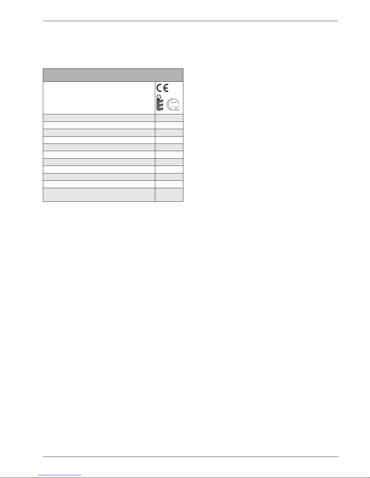
Tab. 1 Technical rules for the installation of thermal solar heating systems (selection) in UK
iUSER NOTE
The installation of the Worcester Solar
System must be carried out in accordance
with the relevant requirements for safety,
current IEE wiring regulations, local
building regulations, building standards
(Scotland) (Consolidation) regulations and
by-laws of the local water company and
health and safety document No 635
(Electricity at Work Regulations 1989).
BS 6795: Latest version

Specifications
6 720 613 577 (2006/04) 5
2 Specifications
Tab. 2 Specifications
FKC SERIES SOLAR PANELS
Certificates
Length 2070 mm
Width 1145 mm
Height 90 mm
Clearance between collectors 25 mm
Fluid content, portrait version Vf0.86 l
Fluid content, landscape version Vf1.25 l
Gross absorber surface area AG2.37 m²
Net absorber surface area 2.23 m²
Net weight, portrait version m41 kg
Net weight, landscape version m42 kg
Permissible operating pressure
of the collector
pmax 6 bar
DIN
0036

Safety
6 720 613 577 (2006/04)
6
3 Safety
This chapter details how the notes for the installation
instructions, as well as the general safety instuctions,
necessary for safe and truoble-free operation, are
arranged in this manual.
Safety and user notes, which specifically refer to the
installation, in the installation manual immerdiately
following the individual installation steps, are found here.
Carefully read the safety instructions before
commencing the installation.
Severe injury and even death, as well as material losses
and environmental damage, may follow if you ignore
safety instuctions.
3.1 Correct use
This installation set holds the thermal solar collectors,
which are installed on sloping roofs with a slope of 25°
to 60°. The collectors can be installed on corrugated and
sheet steel roofs with slopes of between 5° and 65°.
Operating conditions
Only erect the installation set on roofs whose
construction can support the weight. If necessary,
consult a structural engineer or a roofer.
The installation set is suitable for a max. standard snow
load of 2.0 kN/m² and an installation height of max, 20m.
Using appropriate accessories, the installation set can
be used for a max. standard snow load of 3.1 kN/m² and
a max. installation height of 100 m. See Chapter 5.8
"Installing profile rails".
The roof installation set must not be used for fixing any
other objects to the roof. The kit is intended exclusively
for the safe fixing of solar collectors.

Safety
6 720 613 577 (2006/04) 7
3.2 Notes structure
Two levels are identified by signal terms:
Further symbols identifying dangers and user notes:
WARNING!
RISK TO LIFE
Identifies possible dangers which might
lead to serious injury or death if
appropriate care is not taken.
CAUTION!
RISK OF INJURY/SYSTEM DAMAGE
Identifies potentiallydangerous situations,
which might lead to mild or slight injuries
or to material losses.
WARNING!
RISK TO LIFE
from electric shock.
iUSER NOTE
Tip for the optimum utilisation and setting
of the products plus other useful
information.

Safety
6 720 613 577 (2006/04)
8
3.3 Please observe these safety
instructions
WARNING!
RISK TO LIFE
through a fall or falling parts.
BEnsure you have the correct safety
equipment for working on roofs.
BTake appropriate action to prevent
accidents when working on roofs.
BWhilst working on the roof, take all
necessary precautions against a
possible fall.
BAlways wear your personal protective
clothing and safety equipment.
BAfter completing the installation, always
check the secure positioning of the
installed set and that of the collectors.
CAUTION!
RISK OF INJURY
Injury and operating faults can result from
making changes to the system
construction.
BNever change the system construction.
CAUTION!
RISK OF INJURY
Some parts may cause burns, if the
collector and installation materials are
exposed to solar radiation for longer
periods of time.
BAlways wear your personal protective
clothing and safety equipment.
BCover the collector (e.g. with a covering
sheet – available as an accessory
7739 300 399) and the installation
material during the installation as
protection against high temperatures
resulting from solar irradiation.

Before installation
6 720 613 577 (2006/04) 9
4 Before installation
4.1 General notes
Make yourself familiar with the on-site conditions and lo-
cal regulations before commencing the installation.
Check
Bthe delivery for completeness and perfect condition.
Bthe optimum arrangement of the solar collectors.
Take account of the direction of the sunlight (angle of
inclination, southerly direction). Avoid the shade of
high trees or structures and match the collector array
to the shape of the building (e.g. aligned with win-
dows, doors, etc.).
iUSER NOTE
It is recommended that the services of a
roofing company, who are experienced in
working on roofs and will be fully aware of
the risks of working at height are consid-
ered.
Fig. 1 General overview of collector pair – roof mounting
63043965.02-1.SD
63043965.02-1.SD
CAUTION!
RISK OF INJURY
If the collector and its installation material
is left exposed to the sunlight for a long
period, the parts will become hot and may
cause burns.
BWear protective clothing.
BCover the collector (e.g. with
a covering sheet – available as an ac-
cessory 7739 300 399) and the instal-
lation material during the installation
as protection against high tempera-
tures resulting from solar irradiation.
iUSER NOTE
Only use OEM components and replace
any damaged or faulty parts immediately.
iUSER NOTE
Remove broken tiles, shingles or plates in
the area of the collectors and replace
them.

Before installation
6 720 613 577 (2006/04)
10
4.2 Component description
4.2.1 Installation set for the collectors
Roof connection, pan tile roofs, per collector
(Fig. 2):
iUSER NOTE
The installation sets are for mounting and
fixing the collectors in place.
Fig. 2 Installation set for 2 collectors – 1 basic installation set, 1 extended installation set and 2 roof connection installation sets
63043965.03-1.SD
63043965.03-1.SD
123
4
7
3
6
5
8
Basic installation set for each collector array and
for the first collector (Fig. 2):
Extended installation set for each additional collector
(Fig. 2):
Item 1: Profile rail 2 ×Item 1: Profile rail 2 ×
Item 3: Single-sided collector clamp 4 ×Item 2: Double-sided collector clamp 2 ×
Item 7: Anti-slip protection 2 ×Item 7: Anti-slip protection 2 ×
Item 8: M8 screw 4 ×Item 6: Rail connector with threaded studs 2 ×
Item 8: M8 screw 4 ×
Item 4: Roof hook, adjustable 4 ×
Item 5: Sliding nut 4 ×

Before installation
6 720 613 577 (2006/04) 11
4.2.2 Hydraulic connection
Connection kit, per collector array (Fig. 3)
Connection set between the collectors, for each
collector (in two corner protectors, Fig. 4)
iUSER NOTE
One connection kit for each collector ar-
ray will be required. The collectors are
connected together by solar hoses (con-
nection set).
Fig. 3 Connection kit and connection set (illustration shows 2 portrait collectors)
63043965.04-1.SD
63043965.04-1.SD
1 2 3
4
5
7
8
3
4
6
Item 1: Hose clip (1 x spare) 5 ×Item 6: Clamped joint for collector sensor 1 ×
Item 3: Solar hose, length 1000 mm 2 ×Item 7: Size 5 Allen key 1 ×
Item 4: Dummy plug 2 ×Item 8: Hose nozzle R¾ with 22 mm compression fittings 2 ×
Item 5: Solar hose, length 55 mm 2 ×
Fig. 4 Two corner protectors with one connection set
63043965.05-1.SD
63043965.05-1.SD
1
2
Item 1: Hose clip 4 ×
Item 2: Solar hose, length 95 mm 2 ×

Before installation
6 720 613 577 (2006/04)
12
4.3 Other equipment
–Spirit level
–Plumb line
–Filling pump
–Vest harness with safety rope
–Pipe insulation
–Scaffolding
–Roofing ladder
–Crane or mobile hoist
4.4 Transport and storage
Please ensure that the corner protectors are re-
tained. They contain pipework connection pieces
which are required for installation. All components
are protected by transport packaging.
Transport protection for collector connections
The collector connections are protected against damage
by plastic caps.
Storage
The collectors must be stored in dry conditions.
iUSER NOTE
When fitting the roof installation set and
pipework connection, the only tool re-
quired is the size 5 Allen key from the con-
nection kit.
iUSER NOTE
Dispose of the transport packaging in an
environmentally friendly recycling sys-
tem.
Fig. 5 Plastic caps on collector connections
63043965.06-1.SD
63043965.06-1.SD
1
CAUTION!
SYSTEM DAMAGE
through damaged sealing faces.
BDo not remove the plastic caps
(Fig. 5, Item 1) until immediately prior
to installation.
iUSER NOTE
Do not store collectors outside without
protection from the rain.

Before installation
6 720 613 577 (2006/04) 13
4.5 Technical documentation
The solar heating system consists of various compo-
nents (Fig. 6). Installation, operation and maintenance
documentation is provided for each component. Acces-
sories may be accompanied by a separate document.
Fig. 6 Solar heating system components and technical
documentation
6720613577.00-1.SD
6720613577.00-1.SD
2
1
3
4
Item 1: Collector: instructions for roof installation
are enclosed with the connection kit
Item 2: Pump station: instructions enclosed with the
complete station
Item 3: Solar Controller: instructions are enclosed
with the controller.
Item 4: DHW Cylinder: instructions enclosed with the
DHW cylinder.

Before installation
6 720 613 577 (2006/04)
14
4.6 Determining space required on roof
Please note the following minimum space requirements.
Dimension A and B
Area required for the collector array.
Dimension C
At least two tiles to the roof or chimney. Otherwise there
is a risk of damaging the tiles, particularly if the tiles are
laid in mortar.
Dimension D
Roof overhang including gable wall thickness.
Dimension E
Minimum 30 cm for fitting the connection cables in
the attic.
Dimension F
Minimum 40 cm for installing the connection cables in
the attic (if installing a vent, sufficient space must also be
allowed for in the vicinity of the flow outlet).
Please note that the air vent must be the highest point of
the system.
Dimension G
Minimum 50 cm left and right of the collector array for
the connection cables under the roof.
Dimension H
Dimension H is 1.900 mm (1.000 mm for landscape
collectors) and is the minimum distance from the upper
edge of the collector to the lower profile rail, which is in-
stalled first.
Fig. 7 Clearances to be observed
G
H
63043965.09-1.SD
63043965.09-1.SD
Space requirements for portrait collectors: Space requirements for landscape collectors:
Number of collectors Dimension A Dim. B Number of collectors Dimension A Dim. B
2 2.32 m 2.07 m 2 4.17 m 1.15 m
33.49 m 2.07 m 36.26 m 1.15 m
4 4.66 m 2.07 m 4 8.36 m 1.15 m
55.83 m 2.07 m 510.45 m 1.15 m
6 7.06 m 2.07 m 6 12.55 m 1.15 m
78.17 m 2.07 m 714.64 m 1.15 m
8 9.34 m 2.07 m 8 16.74 m 1.15 m
910.51 m 2.07 m 918.61 m 1.15 m
10 11.68 m 2.07 m 10 20.93 m 1.15 m
Tab. 3 Space requirement for portrait collectors Tab. 4 Space requirement for landscape collectors

Fitting the roof connection and profile rails
6 720 613 577 (2006/04) 15
5 Fitting the roof connection and profile rails
5.1 Setting clearances
The dimensions given are guide values that should be
approximately maintained.
Distances of roof hooks
Every profile rail is fastened using two roof hooks
(Fig. 8). See the table for the approximate distance
between the roof hooks.
Distances of profile rails
Set the distance between the top and bottom profile rails
(Fig. 9). Use the table values.
Fig. 8 Distance between roof hooks
z
z
x
x
63043965.11-1.SD
63043965.11-1.SD
iUSER NOTE
On pan tile roofs the tile troughs
determine the true distance between the
roof hooks.
Installation
type
Distance w Distance x Distance z
portrait approx.
1170 mm
610 –
1030 mm
170 – 540 mm
landscape approx. 2090 mm 1520 –
1950 mm
170 – 540 mm
Tab. 5 Distance between roof hooks
iUSER NOTE
Distances x and z should always be
approximately equal to distance w.
Fig. 9 Distance between profile rails
y
y
63043965.12-1.SD
63043965.12-1.SD
Installation
type
Distance y
from to
portrait 1320 mm 1710 mm
landscape 600 mm 820 mm
Tab. 6 Distance (centre-centre) between bottom
and top profile rail
iUSER NOTE
Landscape installation is only possible
if roof battens are max. 420 mm apart.

Fitting the roof connection and profile rails
6 720 613 577 (2006/04)
16
Fig. 10 Fitted profile rails for two collectors
63043965.10-1.SD
63043965.10-1.SD
WARNING!
RISK TO LIFE
Whilst working on the roof, take all
necessary precautions against a possible
fall.
WARNING!
RISK OF INJURY
through a fall or falling parts.
BTake appropriate action to prevent
accidents when working on roofs.
BAlways wear personal protective
clothing and safety equipment.

Fitting the roof connection and profile rails
6 720 613 577 (2006/04) 17
5.2 Pan tile roofs
Fit all roof hooks according to the guide values shown in
tables 5 and 6 on page 15.
5.2.1 Attaching the roof hooks over the roof batten
In its packaged state, the lower part of the roof hook is
folded.
BLoosen the long hexagon nut (Fig. 12, Item 2) on the
roof hook and move the lower part of the roof hook
(Fig. 12, Item 1) to the correct position.
BPush the tile upwards according to the roof hook
positions shown in (Tab. 5 and Tab. 6, page 15).
BAttach in the roof hook in such a way that the front
brace lies in a tile trough (Fig. 13, Item 4).
BPush the lower part of roof hook (Fig. 13, Item 3)
upwards until it touches the roof batten
(Fig. 13, Item 2).
BTighten the long hexagon nut (Fig. 13, Item 1). To do
this, insert the size 5 Allen key into one of the holes
in the hexagon nut and turn.
Fig. 11 Fitted roof hooks for two collectors
63043965.13-1.SD
63043965.13-1.SD
iUSER NOTE
Do not modify the roof construction and
avoid damaging the roof covering. In the
case of roof tiles laid in mortar, lift the tiles
starting with the 3rd row under the roof.
iUSER NOTE
Carefully cut away the base of the tile if
necessary to ensure the tile lies correctly
over the roof hook.
Fig. 12 Turning the lower part of the roof hook
Fig. 13 Roof hook located in place (some tiles have been
removed to show the example in more detail)
63043965.14-1.SD
63043965.14-1.SD
12
63043965.15-1.SD
63043965.15-1.SD
1
3
4
4
2
5
CAUTION!
SYSTEM DAMAGE
through subsequent loosening of the long
hexagon nut on the roof hook. When the
nut is tightened, adhesive is activated
which bonds the joint securely after one
hour.
BIf the nut becomes loose after this
time, it must be tightened on-site
(e.g. lock washer).
iUSER NOTE
The serated washer (Fig. 13, Item 5)
must grip the teeth on the lower part of the
roof hook.

Fitting the roof connection and profile rails
6 720 613 577 (2006/04)
18
5.2.2 Fastening roof hooks to joists
Alternatively, the roof hook can also be used for
fastening to the joist.
According to the roof hook positions shown in (Tab. 5
and Tab. 6, page 15), sufficiently strong boards must be
attached to the joists so that the roof hook can be fitted
between the joists.
BLoosen the long hexagon nut (Fig. 14, Item 2).
BInsert bolt into upper hole (Fig. 14, Item 3).
BLoosely fasten lower part of roof hook
(Fig. 14, Item 1). Do not tighten the connection yet.
BLay front brace onto the tile so that when subjected
to a load it lies in a tile trough (Fig. 15, Item 3).
The roof hook must have some clearance along the
upper edge of the tile (Fig. 15, Item 4). Adjust the top of
the tile if necessary.
BPush the lower part of the roof hook down until it lies
on the joist or on the boards (Fig. 15, Item 6).
BTighten the long hexagon nut (Fig. 15, Item 1). To do
this, insert the size 5 Allen key into the hole in the
hexagon nut and turn.
BUsing suitable screws, fasten the lower part of the
roof hook into the first (Fig. 15, Item 2) and second
holes (at least) of the joist.
Fig. 14 Fastening roof hooks to joists
Item 1: Lower part of roof hook
Item 2: Long hexagon nut
Item 3: Upper hole for fastening the lower part
Item 4: Pack if necessary
Item 5: Cut off if necessary
63043965.16-1.SD
63043965.16-1.SD
2
1
3
5
4
iUSER NOTE
With some roof coverings it may be
necessary to pack the lower part of the
roof hook (Fig. 14, Item 4) with boards so
that the upper part of the roof hook lies on
top of the tile.
CAUTION!
SYSTEM DAMAGE
through breakage of the roof hook if the
bolt is not positioned in the upper hole,
resulting in uneven load distribution.
Fig. 15 Roof hook fitted (some tiles have been removed for a
better view)
Item 1: Long hexagon nut
Item 2: Screw for fastening roof hook
Item 3: Front brace
Item 4: Adjust the tile as necessary to fit the roof hook
Item 5: Serated washer
Item 6: Board
63043965.17-1.SD
63043965.17-1.SD
1
4
6
3
2
5
3
iUSER NOTE
The serated washer (Fig. 15, Item 5)
must grip the teeth on the lower part of the
roof hook.

Fitting the roof connection and profile rails
6 720 613 577 (2006/04) 19
5.3 Crown tile roofs
During installation, please maintain the required
distances (w, x and y) between the roof hooks as
detailed in (Tab. 5 and Tab. 6, page 15).
According to the roof hook positions shown in (Tab. 5
and Tab. 6, page 15), sufficiently strong boards
(Fig. 16, Item 1) must be attached to the joists (cut out
counter-battens) so that the roof hook can be fitted
between the joists.
Preparing roof hook
Before installing, the lower part must be moved to the
correct position.
BLoosen the long hexagon nut (Fig. 17, Item 2).
BInsert bolt into upper hole (Fig. 17, Item 3).
BLoosely fasten lower part of roof hook
(Fig. 17, Item 1). Do not tighten the connection yet.
Fig. 16 Fit boards/planks if necessary
63043965.18-1.SD
63043965.18-1.SD
1
1
iUSER NOTE
Consult a roofer when installing on a roof
with crown tiles.
iUSER NOTE
If the roof has been fitted with boards, the
same roof hook as with pan tile roofs can
be used (page 17). It may also be
possible to fit the roof hooks over buttons.
Fig. 17 Repositioning lower part of roof hook
Item 1: Lower part of roof hook
Item 2: Long hexagon nut
Item 3: Upper hole for fastening the lower part
Item 4: Cut off if necessary
63043965.16-1.SD
63043965.16-1.SD
1
3
2
4
CAUTION!
SYSTEM DAMAGE
through breakage of the roof hook if the
bolt is not positioned in the upper hole,
resulting in uneven load distribution.

Fitting the roof connection and profile rails
6 720 613 577 (2006/04)
20
Fitting the roof hook
BPush the lower part of the hook down until it lies on
the joist or on the board (Fig. 18, Item 1).
BTighten the long hexagon nut (Fig. 19, Item 1). To do
this, insert the size 5 Allen key into the hole in the
hexagon nut and turn.
BUsing suitable screws, fasten the lower part of the
roof hook into the first (Fig. 19, Item 3) and second
holes (at least) of the joist or board.
BCut the adjacent crown tiles (Fig. 20, Item 1) to size
(dashed line, Fig. 20, Item 2).
Fig. 18 Fitted roof hook
Fig. 19 Fitted roof hook – cross section showing shortened
lower part of roof hook
Item 1: Long hexagon nut
Item 2: Serated washer
Item 3: Screw for fastening roof hook
63043965.20-1.SD
63043965.20-1.SD
1
63043965.21-1.SD
63043965.21-1.SD
1
3
2
CAUTION!
BUILDING DAMAGE
caused by leaks.
BFit each roof hook centrally on a crown
tile.
iUSER NOTE
If the roof battens are too close together,
remove the lower part of the roof hook
between the second and third holes.
iUSER NOTE
The serated washer (Fig. 19, Item 2)
must grip the teeth on the lower part of the
roof hook.
Fig. 20 Roof hook with covered roof
63043965.65-1.SD
63043965.65-1.SD
2
1
Table of contents
Other Worcester Solar Panel manuals
Popular Solar Panel manuals by other brands

Trunsun Solar
Trunsun Solar TSMxxx-72 series installation manual

Furrion
Furrion FURRIONNET-ZERO FSFP10MW-BL instruction manual

Kyocera
Kyocera KD130GX-LP installation manual

Kings Adventure
Kings Adventure 250W user manual

Suntactics
Suntactics sCharger-5 manual

Schletter
Schletter FlatGrid installation manual