Workhorse Products QUARTZ FLASH User manual

QUARTZ FLASH
OWNER’S MANUAL
WWW.WORKHORSEPRODUCTS.COM
PARTS & SUPPLIES ARE AVAILABLE ONLINE AT:
https://support.workhorseproducts.com/store/

23730 E. SOUTHERN AVE., PHOENIX, AZ 85040 | USA
CONGRATULATIONS!
You are now the proud owner of a Quartz Flash Unit.
We thank you for choosing Workhorse Products!
While our packaging has been designed to handle normal shipping conditions,
we cannot foresee damages caused by the carrier and are not responsible for
damages that occur during transportation.
Please check the contents of the packaging for damages immediately.
If shipping damage has occurred:
1) Contact the carrier to file a claim immediately
2) Contact Workhorse Products at 800.778.8779
---- AND ----
THE IMPORTANCE OF THE OWNER’S MANUAL
The purpose of the Owner’s Manual is to familiarize you with the parts and operations
of the product. There are step-by-step instructions to assemble the product as well as
troubleshooting information. Also included are explanations of the product’s key features
and additional information that will help with the maintenance of your product.

3
800.778.8779 | WORKHORSEPRODUCTS.COM
TABLE OF CONTENTS
INTRODUCTION & SAFETY INFORMATION
SPECIFICATIONS
ASSEMBLY
STEP 1: UNCRATING
STEP 2: INSERTING THE QUARTZ ELEMENTS
STEP 3: CONNECTING THE POWER AND CONTROL
STEP 4: CONNECTING THE FLASH TO YOUR PRESS
CONTROLS
ADJUSTMENTS
TOUCH SCREEN CONTROLS
BASIC OPERATION
WIRING DIAGRAMS
LIMITED WARRANTY
4
5
6
7
8-9
10-11
12
13
14
15-17
18
19

43730 E. SOUTHERN AVE., PHOENIX, AZ 85040 | USA
SAFETY INFORMATION
WARNING!
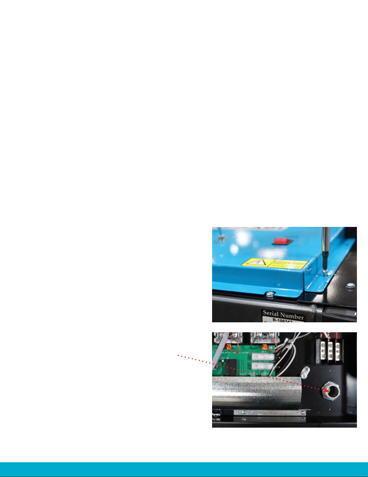
RISK OF ELECTRICAL SHOCK! Turn ALL power to the unit OFF before service.
All service should be done by or under the supervision of a trained technician.
THIS ELECTRIC FLASH CURE UNIT IS INTENDED SOLELY FOR THE PURPOSE OF CURING
INK ONTO FINISHED TEXTILES AND CUT GOODS. THIS FLASH IS NOT INTENDED FOR
USE IN HEATING, CURING OR BAKING OF ANY OTHER MATERIALS WHATSOEVER. THIS
FLASH IS INTENDED FOR IN-DOOR USE ONLY.
THE EXCLAMATION WITHIN AN EQUILATERAL TRIANGLE IS INTENDED TO ALERT THE
USER OF IMPORTANT SAFETY PRECAUTIONS SHOP PERSONNEL SHOULD BE AWARE
OF DURING OPERATION.
For your safety, do not store or use gasoline or other flammable vapors and liquids in the vicinity
(at least three feet) of this or any other appliance.
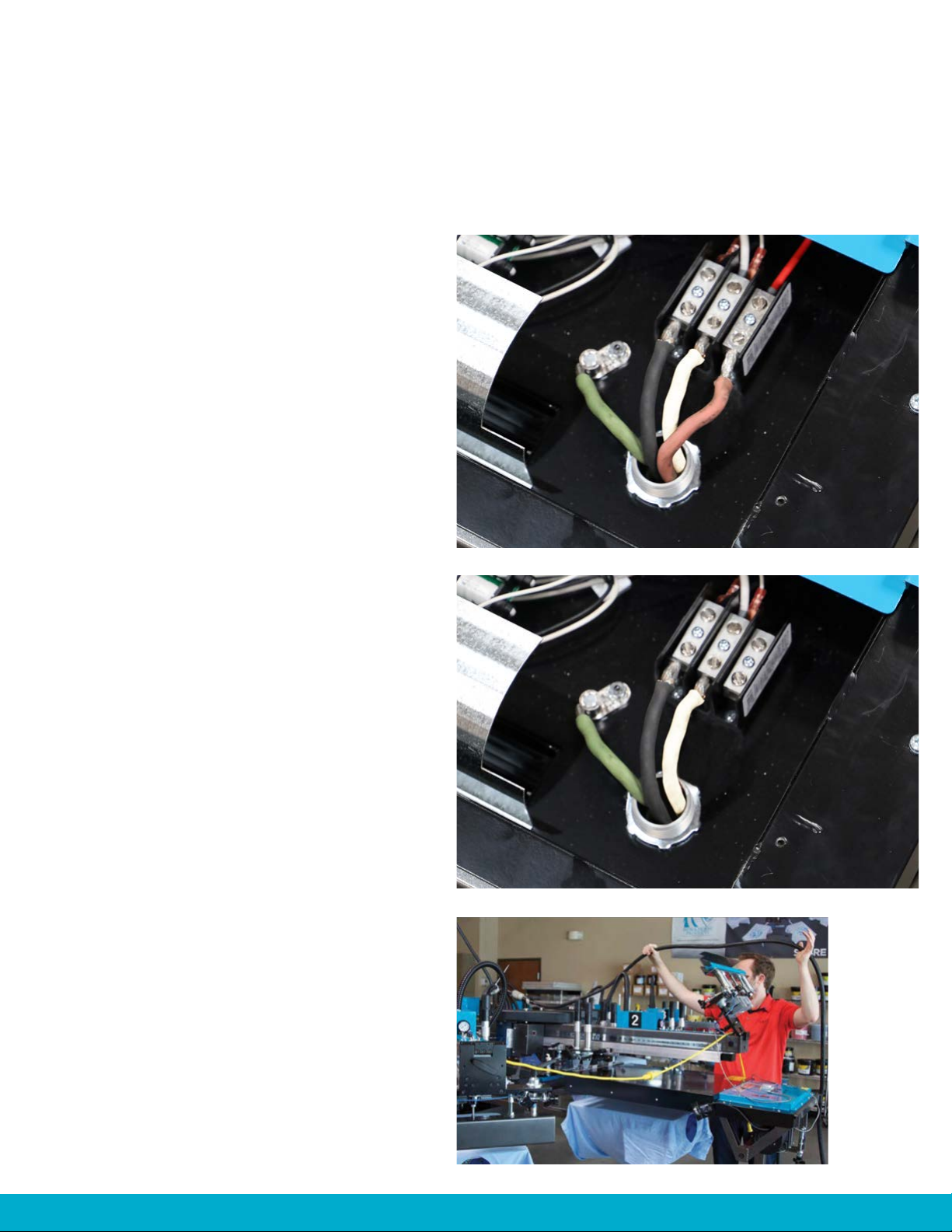
Proper grounding (a ground rod at the equipment footing), according to NEC requirements, must
be provided during electrical connection by a QUALIFIED ELECTRICIAN.
Never alter the internal wiring of this machine.
Never place any item other than the stock to be cured under the flash heaters.
Once in position lock wheels before using the flash unit.
Keep all loose articles (including clothing, hair, jewelry, etc.) away from the hot elements.
Never leave the machine unattended when it is operating.
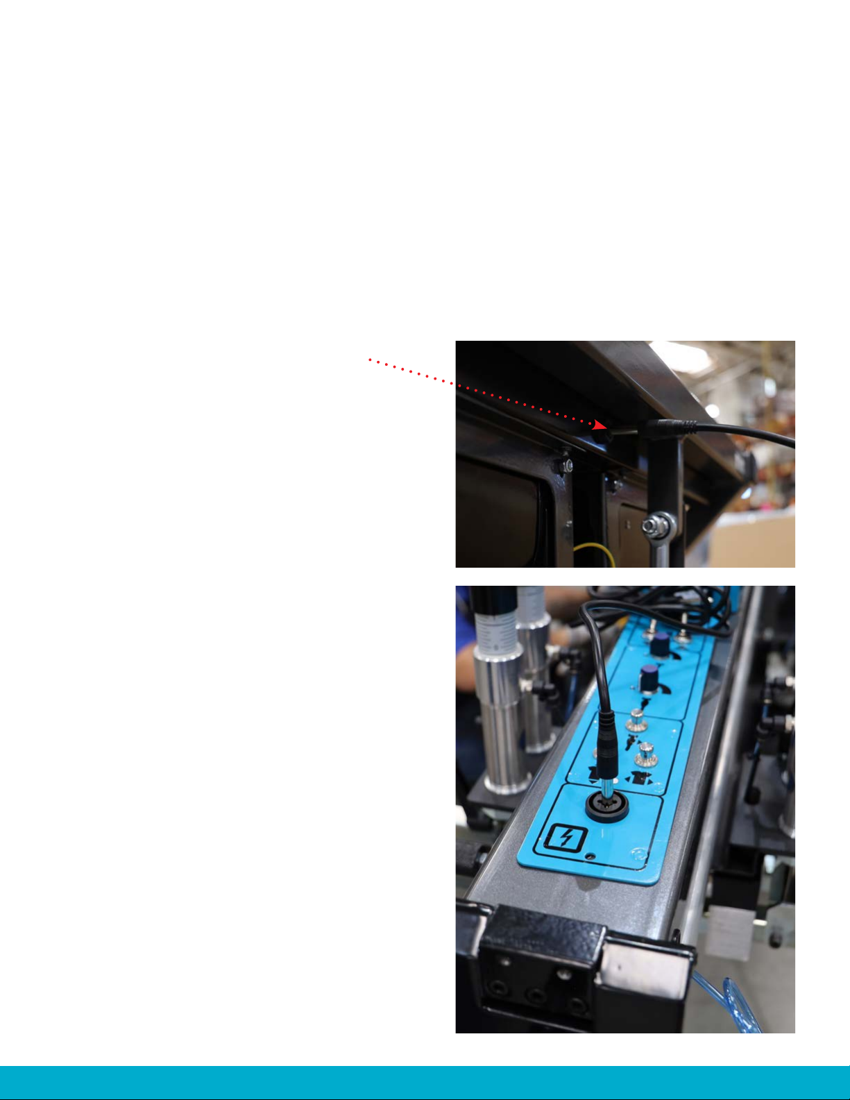
Do not perform maintenance on this machine until all power has been shut off at the flash AND at
the incoming power circuit breaker. Also, disconnect the control cable leading to the machine.

5
800.778.8779 | WORKHORSEPRODUCTS.COM
SPECIFICATIONS
PARTS FOR ASSEMBLY
Part Number
Flash Area
Power Requirements
SQF-2205
20” x 24”
(51cm x 61cm)
ELECTRIC
1-Phase, 240V
12,800W, 60A
(8) 1,600W Elements
SQF-2200
20” x 24”
(51cm x 61cm)
ELECTRIC
3-Phase, 240V
14,400W, 40A
(9) 1,600W Elements
SQF-2220
20” x 32”
(51cm x 81cm)
ELECTRIC
3-Phase, 240V
19,200W, 50A
(12) 1,600W Elements
DESCRIPTION
Quartz Flash
6’ Cable
Quartz Elements
SQF-2205
SQF-2200
SQF-2220
PART NO. QTY.
Pre-assembled
32-C-2841
10-22-012
1
1
8
9
12

63730 E. SOUTHERN AVE., PHOENIX, AZ 85040 | USA
ASSEMBLY
STEP 1: UNCRATING
The Quartz Flash ships fully assembled.
Remove the wooden outer shell and the
wooden caps holding the legs in place.
Carefully lift the flash off the pallet.
The flash is now accessible and can roll into
place.
The hardware is inside of the plastic
wrapping and contains the Quartz Heating
Elements.
• Handle with care
• DO NOT touch the elements with bare hands
• Use a clean cloth or latex gloves when handling
the elements
The S/O cable and plug ends are not included
1.
2.
TOOLS NEEDED
Phillips Head Screwdriver
Drill (preferably)
Hammer
•
•
•

7
800.778.8779 | WORKHORSEPRODUCTS.COM
ASSEMBLY
STEP 2: INSERTING THE QUARTZ ELEMENTS
IMPORTANT:
SQF-2205 (1-phase): Requires 8 elements
(You will see 9 slots. Leave the spot open at the
position nearest the control panel. This will allow you
to flash the bottom of images)
SQF-2200 (3-phase): Requires 9 elements
SQF-2220 (3-phase): Requires 12 elements
DO NOT handle the quartz elements
with bare hands. The oils from skin can
contaminate the quartz tubes.
USE a clean cloth or gloves to insert the
elements
DO NOT HANDLE HOT ELEMENTS!
NOTE:
If the elements do become contaminated use
a soft cloth and isopropyl rubbing alcohol
to clean them. Never attempt to clean the
elements or any part of the flash with the
power connected. Make sure the flash is
disconnected and cooled down before any kind
of maintenance is done.
The sockets that hold the tubes are spring-
loaded. Insert the end of the tube into the
socket and gently apply pressure while
inserting the opposite end into the mating
socket.
Install the rest of the elements.
1.
2.
TOOLS NEEDED
Clean cloth
Latex or cotton gloves
PARTS NEEDED
Elements••
•

83730 E. SOUTHERN AVE., PHOENIX, AZ 85040 | USA
ASSEMBLY
STEP 3: CONNECTING THE POWER & CONTROL
An SO cable is needed for these next steps. (NOTE: It is not included with the product)
The flash requires a power connection to be brought to the unit and hardwired directly to the
power distribution block.
There are 2 options to connect the power:
1) Hardwire to an electric panel
2) Fitting the SO cable with plug ends
Start by hardwiring the SO cable to the flash.
Remove the teal cover by unscrewing the 11
screws located around the edge of the cover.
After removing the cover, locate the Power
Cable Access hole on the right side of the
flash. Feed the end of the SO cable through
this hole to connect to the power distribution
block.
1.
2.
TOOLS NEEDED
Phillips Head Screwdriver
PARTS NEEDED
SO Cable
Plug ends (optional)
•
•
•

9
800.778.8779 | WORKHORSEPRODUCTS.COM
Attach the other end of the SO cable to
the power source.
It is recommended to use a ceiling drop as
the power source.
This allows the SO cable to lay across
the print head the flash is being used on;
eliminating the dangers of having cables
run along the ground.
(NOTE: The
flash in this
example may
be a different
model than
yours)
1.
2.
3.
1.
2.
3.
3.
ASSEMBLY
STEP 3: CONNECTING THE POWER & CONTROL
3-PHASE CONNECTION
Requires 3 hot wires and 1 ground wire
1-PHASE CONNECTION
Requires 2 hot wires and 1 ground wire
Feed the SO Cable up through the
Power Cable Access (A) from the
bottom of the control box.
Connect the 3 hot wires to the
open legs on the back of the power
distribution block (C, D and E).
Connect the earth ground wire to the
ground lug (B).
Feed the SO Cable up through the
Power Cable Access (A) from the
bottom of the control box.
Connect the 2 hot wires to the
open legs on the back of the power
distribution block (C and D).
Connect the earth ground wire to the
ground lug (B).
(A)
(A)
(B)
(B)
(C)
(C)
(D)
(D)
(E)

10 3730 E. SOUTHERN AVE., PHOENIX, AZ 85040 | USA
ASSEMBLY
STEP 4: CONNECTING THE FLASH TO YOUR PRESS
NOTE: This connection method only works with a Workhorse Cutlass or Sabre. All other machines
use the IR Sensor.
Plug one end of the jack into the flash.
Plug the other end into the print head. Once
the flash is plugged into the end of the print
head the touch screen control will recognize
that the flash is in place.
The flash receptacle on the press is identified
with a lightning icon on the end of the print
head. This round, black receptacle is where
you plug in the cable jack.
The power switch for the flash must be in the
“ON” position for the press to recognize the
flash and for the flash to function.
1.
2.
3.
PARTS NEEDED
6’ Cable Jack•

11
800.778.8779 | WORKHORSEPRODUCTS.COM
ASSEMBLY
STEP 4: CONNECTING THE FLASH TO YOUR PRESS

12 3730 E. SOUTHERN AVE., PHOENIX, AZ 85040 | USA
TIMER TEST + TIME KNOB
These features are used in conjunction with the IR Sensor (pictured below). The IR Sensor is
used with older Workhorse Autos, manual presses and non Workhorse manufactured presses.
Timer test = toggle switch that is used to turn the bulbs on to ensure they are working and to
confirm proper timing
Time knob = manually controls the duration of the flash (left for shorter duration, right for
longer duration)
IR sensor = recognizes when the pallet
indexes and triggers the flash
To use these features the flash CANNOT
be connected to your press via the
communication cable.
CONTROLS
HEAT ZONE OPTIONS
Heat zone options allow the operator to choose which part of the flash is used. Zones can be
used individually or in combinations. This allows you to control the amount of heat needed to
flash an image. Heat zone options work in both Sensor and Plug-N-Go modes.
Heat Zone 1 = Bottom Elements
Heat Zone 2 = Middle Elements
Heat Zone 3 = Top Elements
POWER INDICATOR
The red light will illuminate when the flash is on.
(A)
(B)
(C)
(D)
(E)
(A) (B) (C) (D) (E)

13
800.778.8779 | WORKHORSEPRODUCTS.COM
ADJUSTMENTS
HEIGHT OF THE FLASH
SABRE SABRE
TILT ADJUSTMENT
SABRE
In order to place the flash into the proper position
you must loosen the T-knob and pull the hinged front
screen clamp up and over the top of the print head.
This provides access to roll the flash over the platen
in it’s table up position.
CUTLASS
In order to place the flash into the proper
position you must remove the end levers,
disconnect the front airlines from the cylinders
and slide the assembly out the end of the head.
This provides access to roll the flash over the
platen in it’s table up position.
Unlock the locking lever, then
use the crank handle to adjust
the height of the element tray.
Once set to the desired height
re-tighten the locking lever.
The tilt adjustment is to
level the heating elements
so that they are parallel
with the platen.
Crank Handle
Locking Lever
ADJUST THE CASTERS FOR
LEVELING
Turn the knob until flash
is level.
PLACING THE FLASH UNDER THE PRESS
CUTLASS

14 3730 E. SOUTHERN AVE., PHOENIX, AZ 85040 | USA
TOUCH SCREEN CONTROLS
PLUG-N-GO MODE
When the flash is in plug-n-go mode a lightning bolt icon will appear on the press graphic.
Touch the print head to display the sub menu with the options to control the flash.
ACTIVE
Select “Yes” for the print head to be active
FLASH HEAD
Select “On” for the print head to be active
FLASH WITH or AFTER INDEX
“WITH”: The flash will turn on when the platens begin to move from one station to another,
allowing the flash to have more time to heat up while the press is indexing. This mode is
recommended when you need a hotter, faster flash.
“AFTER”: The flash will turn on after the press completes index. This mode is recommended
when you need a cooler flash (which is necessary for sensitive compound fabrics).
FLASH TIME
The flash time represents the amount of time the press holds the platens in the up position
until the flash curing process is complete. Optimization of this time is essential because it will
have a dramatic effect on production numbers. The time can be lowered after the press has
been running and the platens are heated. Be wary of setting the flash timer for too long, this
could ruin the ink and not adhere if the layer is too cured.
(A)
(B)
(C)
(D)

15
800.778.8779 | WORKHORSEPRODUCTS.COM
PLUG-N-GO CONNECTION
The Quartz Flash should be installed with extra cable to allow it to be moved to any printhead on
the press. As a plug-n-go it is designed to connect to any compatible Workhorse Press (Cutlass or
Sabre).
STEP 1
Move or remove the front screen clamp, this process varies by model of machine. (See page 13 for
instruction on moving clamp)
STEP 2
From the control panel of the press, raise the printing platens to the table up position.
STEP 3
Adjust height of flash to 1.5” above printing platen in table up position (this height is a suggested
starting point and will vary by job). Also using the tilt adjusment make the flash parallel to the
printing platen front to back. Finally, the flash needs to parallel from left to right. This adjustment
is made with the knobs on the wheels of the flash base. (See page 13 for instruction)
STEP 4
Attach the communication cable from the communication port on the flash to the com. port on the
desired printhead. On compatible machines, once the connection is made the press will recognize
that printhead as a flash head. Connection will be indicated on the tablet with the lightning bolt
symbol on the representation of the printhead.
STEP 5
Once plugged into the press the flash is now controlled from the tablet. To program touch the
desired printhead which will enable the menu.
1) Select Active
2) Select “Flash with Index” for most fabrics OR Select “Flash after Index” for heat sensitive fabrics
3) Set flash time (suggested starting point would be 5 seconds and adjust as needed)
BASIC OPERATION

16 3730 E. SOUTHERN AVE., PHOENIX, AZ 85040 | USA
BASIC OPERATION
USING FLASH WITH IR SENSOR
This applies to Workhorse Presses without communication ports, auto presses from other
manufacturers, and manual presses. In this mode the Sensor on the flash sees the moving platen then
turns on the elements and starts the timer. Once the preselected time set on the timer has elapsed
the heating elements will shut down until the sensor sees the next platen moving into position.
STEP 1
Move or remove the front screen clamp, this process varies by model of machine.
(See page 13 for instruction on moving clamp)
STEP 2
From the control panel of the press, raise the printing platens to the table up position.
STEP 3
Adjust height of flash to 1.5” above printing platen in table up position (this height is a suggested
starting point and will vary by job). Also using the tilt adjusment make the flash parallel to the printing
platen front to back. Finally, the flash needs to parallel from left to right. This adjustment is made with
the knobs on the wheels of the flash base. (See page 13 for instruction)
STEP 4
Set the timer on the flash at the half-way point. With no communcation cable plugged into the press
the IR Sensor will automatically be active. To operate simply rotate the next platen in front of the
flash. Adjust timer as needed for fabric type.

17
800.778.8779 | WORKHORSEPRODUCTS.COM
Set up of the Flash remains the same but programming at the tablet will vary by program selected.
ORBITAL MODE
In Orbital mode the machine is programmed to cycle around more than one rotation.
To print a set # of colors on each rotation and moving past the flash unit before starting the colors
on the next rotation.
STEP BACK MODE
In this mode the flash is placed in the printhead between 2 colors and the single flash unit will cure
both colors by rotating the platens in both directions (this feature is only offered on the Cutlass
and Sabre products).
NO POWER TO FLASH
Check the power switch. Is the power cable plugged in? Check circuit breaker from the building.
ONE OR MORE LAMPS IS NOT WORKING
Check Zone switches to make sure proper switch is on. Verify Lamp is in sockets on both ends.
Swap non-working lamp with one that works.
LAMPS STAYING ON ALL THE TIME
Unplug control cable between Flash and Printhead. Check relays for sticking closed.
FOR TECH SUPPORT
PLEASE CALL 800.778.8779 option 2
ADVANCED OPERATION
TROUBLESHOOTING

18 3730 E. SOUTHERN AVE., PHOENIX, AZ 85040 | USA
WIRING DIAGRAM

19
800.778.8779 | WORKHORSEPRODUCTS.COM
REGISTRATION FORM
FOR WARRANTY TO TAKE PLACE YOU MUST EMAIL THIS FORM BACK TO:
Although every effort has been made to provide accurate specifications, Workhorse Products does not assume any
liability for damages, whether consequential or incidental, that may result from the use or misuse of the indicated
specifications. Workhorse Products requires the use of a licensed industrial electrician for the installation of
electrical service to equipment requiring electrical power.
Workhorse Products reserves the right to alter specifications in the manufacture of its products. It is understood and
agreed that Seller’s liability for any equipment whether liability in contract, in tort, under any warranty, in negligence,
in strict liability or otherwise shall not exceed the return of the amount of the purchase price paid by Buyer. Not
withstanding the foregoing provision, under no circumstances shall Seller be liable for special, indirect or consequential
damages. The price stated for the equipment is a consideration in limiting Seller’s liability. No action regardless of
form, arising out of the transactions under this Agreement may be brought by Buyer more than fifteen (15) years after
the cause of action has occurred. Our warranty is specified, is exclusive and no other warranty, whether written or
oral, is expressed or implied. Workhorse Products specifically disclaims the implied warranties of merchantability and
fitness for a particular purpose. Equipment manufactured or sold by Workhorse Products is warranted against defects
in workmanship and materials for a period of one year from receipt by customer. All warranties initiate from date of
shipment to original customer. Replacement parts are covered for the term of the equipment warranty period. Parts
not under warranty are covered for thirty (30) days from receipt by customer. Any part found by Workhorse Products to
be defective in material or workmanship within the stated warranty period will be replaced or repaired at Workhorse’s
option without charge.
AFTER OBTAINING AN RMA# SEND RETURNED FREIGHT PREPAID TO:
3730 E. Southern Avenue, PHOENIX, AZ 85040 USA.
Written authorization must be obtained from Workhorse before any part will be accepted. Replacement parts are
sent out freight collect. Parts sent out prior to receiving defective require a credit card hold for cost plus freight.
Upon return of defective part, if it is deemed that the part was not damaged by customer but failed, the cost of the
replacement part will be refunded.
This warranty does not extend to expendable parts such as filters, fuses, elements and brushes, casters. Workhorse
does not warrant failure of parts or components resulting from misuse or lack of proper maintenance. Installation,
inspection, and maintenance costs are the sole responsibility of the purchaser.
Company Name:
Address:
City:
State:
Country:
Zip Code:
Model Number:
Date Purchased:
Contact Name:
Phone Number:
Fax Number:
Email:
Cell Number:
Serial Number:
Date Purchased:
LIMITED WARRANTY

WWW.WORKHORSEPRODUCTS.COM
PARTS & SUPPLIES ARE AVAILABLE ONLINE AT:
https://support.workhorseproducts.com/store/
67-1570 REV B
This manual suits for next models
3
Table of contents
Other Workhorse Products Industrial Equipment manuals