WorldWide Electric Motor WDFC Quick Start Guide
This guide and all referenced information is intended for qualied personnel only.
For additional information, please consult the WDFC User Manual
1-800-808-2131
8
WDFC Quick Start Guide
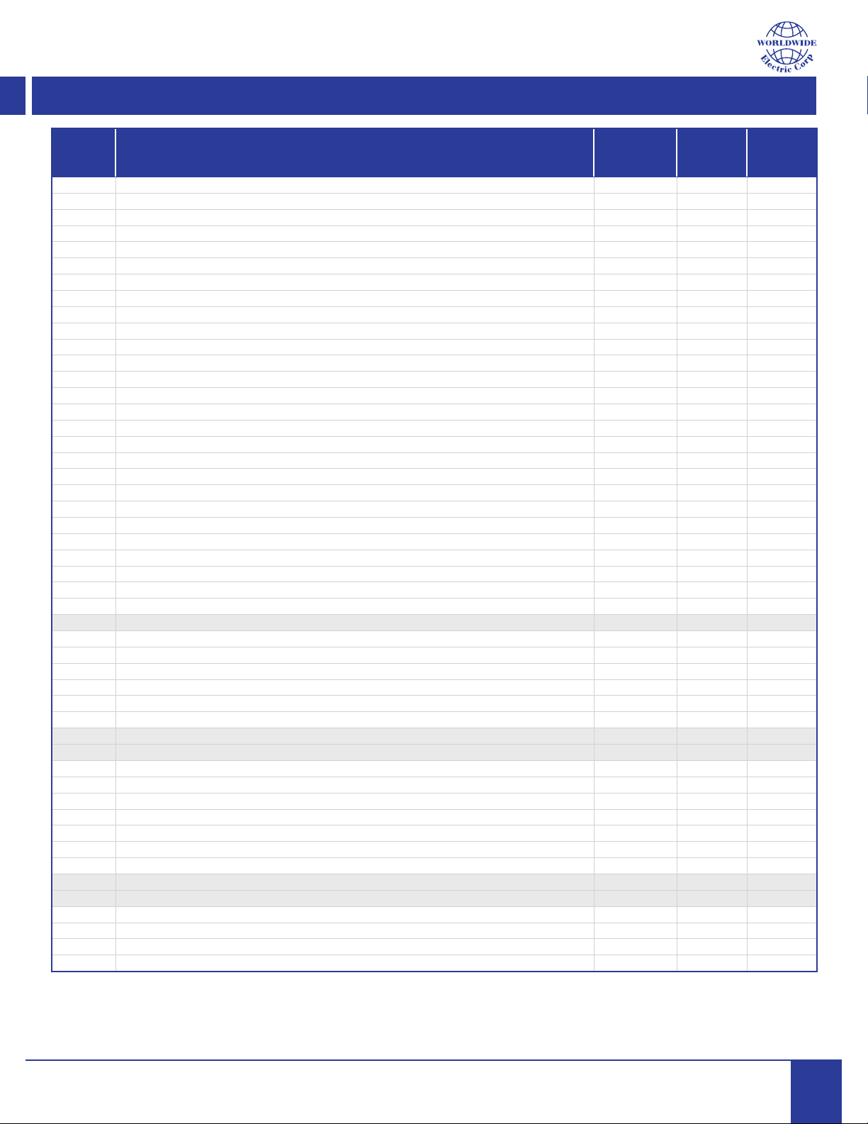
Common Parameters
Group
Name
Description
See drive manual for complete conguration capabilities
NOTE: Press [ESC] key to escape from a Group
Default
Value
Value
Range
New
Value
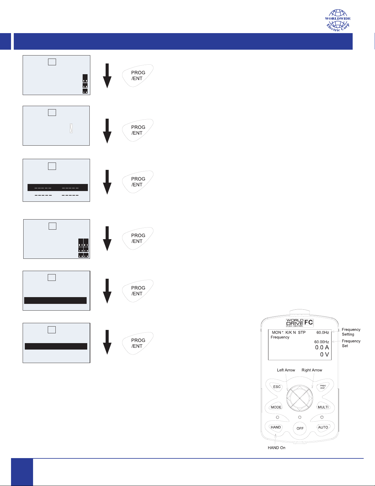
CNF-61 Easy Start Settings: 0 = Disabled; 1 = Enabled 1 0-1
CNF-40 CNF-40 = 1 Defaults ALL Groups in VFD: 0 = No; see manual for full selection chart 0 0-15
Restarting the VFD will activate Easy Start on. Set KEYPAD values as follows:
DRV-01 Cmd Frequency: set by the keypad HZ Low/High Freq
DRV-06 Command Source: 0 = Keypad; 1 = FX/RX1; 2 = FX/RX2; 3 = Int 485; 4 = Field Bus 3 0-5
DRV-07 Frequency Setting Method: 0 = Keypad1; 2 = V1; 4 = V2; 5 = I2; 6 = Int485; 8 = FldBus 0 0-11
BAS-10 60/50Hz Sel = Set to motor rated frequency
DRV-14 Motor Capacity = Set to motor HP
BAS-11 Pole Number = Set to motor pole number (Example 4-pole = 1800rpm)
BAS-13 Rated Curr = Set to motor rated current
BAS-15 Rated Volt = Set to motor rated voltage
BAS-19 AC Input Voltage = Set to AC Line Voltage to VFD
PRT-08 Reset Restart: Set Bit 00 or 11 0 11
PRT-09 Restart number of attempts 0 0-9
Drive Group
DRV01 Cmd Frequency: set by the keypad Hz Low/High Freq
DRV02 Keypad - VFD Run Direction: 0= Reverse; 1 = Forward Fwd Fwd/Rev
DRV03 Accel time in seconds 20.0 0.0-600.0
DRV04 Decel time in seconds 30.0 0.0-600.0
DRV06 Command Source: 0 = Keypad; 1 = FX/RX2; 3 = Int 484; 4 = Field Bus 3 0-5
DRV07 Frequency Setting Method: 0 = Keypad1; 2 = V1; 4 = V2; 5 = I2; 6 = Int485; 8 = Fld Bus 0 0-11
DRV09 Control Mode: 0 = V/F; 1 = Slip Comp; 2 = Resv; 3 = IM Sensorless; 4 = PM Sensorless V/F 0-4
DRV14 Motor HP size / capacity .5-800
DRV15 Torque Boost: 0 = Manual; 1 = Auto; 2 = Auto 2 Manual 0-2
DRV18 Base Frequency: VFD output frequency when running at rated voltage 60.00 30-400hz
DRV19 Start Frequency: frequency VFD starts voltage output 0.50 0.01-10.00hz
DRV20 Maximum Frequency in Hz: set upper & lower frequency limits 60.00 4.00-500.00Hz
DRV21 Displayed units: Hz/RPM Select: 0=Hz Display and 1 = RPM Display 0 0-1
DRV30 kW/HP Unit Selection: 0 = kW; 1 = HP kW 0-1
BAS Basic Group 0
BAS07 V/F Pattern: 0 = Linear; 1 = Square; 2 = User V/F; 3 = Square 2 0 0-3
BAS09 Time scale for Acc/Dec Ramps: 0 = 0.01 sec; 1 = 0.1 sec; 2 = 1 sec 0 0-2
BAS10 Base frequency: 0 = 60Hz; 1 = 50 Hz (input power freq) 60.00 60/50Hz
BAS11 Motor pole number (total poles - NOT pole pairs): Ex: 4-pole = 1800rpm motor 4 2~48
BAS13 Rated Current: Motor nameplate Full Load Amps
BAS14 Motor No Load Current in Amps (typical value of 20-40% of FLA)
BAS15 Motor rated voltage: VFD model specic 230/460v
BAS19 VFD AC input power voltage 230/460v
BAS20 Auto tuning: 0=None; 1=All Rotation; 2=All Static; 3=Rotate Lsigma; 6=Static 0 0~6
ADV Advanced Group
ADV01 Acc Pattern: 0=Linear and 1 = S-Curve
ADV02 Decel Pattern: 0=Linear and 1 = S-Curve
ADV08 Stop mode: 0 = Decel; 1 = DC Brake; 2 = Free Run; 3 = Resv; 4 = Power braking 0 0-4
ADV09 Run Prevent: 0 = None; 1 = FWD Prevent; 2 = REV Prevent 0 0-2
ADV24 Frequency limit: 0= No; 1 = Yes: must enable to set ADV25 & ADV26 0 0-1
ADV25 Frequency low limit: 0.0 to high limit 0.50 0-400 hz
ADV26 Frequency high limit: minimum frequency to maximum frequency 60.00 0.1-400 hz
ADV64 Cooling fan control: 0 = During Run; 1 = Always On; 2 = Temp Control 0 0-2
Note: Shaded areas above denote most frequently used parameters