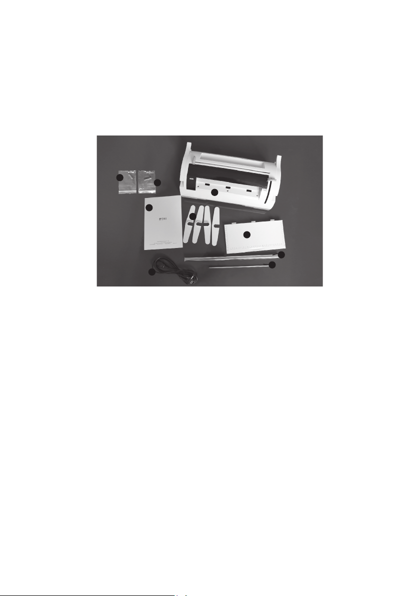
Woson SELINA User manual


1
SELINA Sealing Machine
Operation Instruction
Dear Customer,
Thank you for choosing the new generation sealing machine SELINA!We hope it will perform to your full satisfaction. This
manual describes all procedures for the correct installation and use of the equipment.
Should you have any questions or suggestions concerning this product or our support, do not hesitate to contact us.
Note, warning and danger symbols used through the manual
NOTE
PAY SPECIAL ATTENTION:NOTES FOR PROPER INSTALLATION AND MAINTENANCE
PROCEDURES AND USE METHODS.
WARNING
THIS SYMBOL INDICATESA POTENTIAL DANGER OF INJURY.FOLLOW THE PROCEDU-
RES DESCRIBED IN THE MANUAL TO AVOID INJURING THE USER AND/O.
DANGER
THIS SYMBOL SIGNALSA POSSIBLE DANGER FOR PEOPLE.FOLLOW THE SUGGESTED
PROCEDURE IN ORDER TO PREVENT POSSIBLE DAMAGE TO USERS AND/OR OTHERS.
DANGER
POTENTIAL HAZARD DUE TO HIGH TEMPERATURE.
Symbols on equipment
Potential hazard due to high temperature.
Equipment in accordance with applicable directives.
Symbol for disposal in accordance with Directive 2002/08/EC and 2003/108/EC.
Consult the user manual.

Customer record:
Please note the product model, serialnumber on the nameplate of the productandcomplete the following line.
Whenyou contact the distributoror supplierforafterservice, please use theserial number.
Model: Serialnumber:
Cautions:
Please read all the safety and operation procedures in the instruction manual before you use this product.
Following the instructions will help you operate this device safely and easily.Please always operate the device in strict
accordance with the instructions provided.
Please retain the instructions and customer record in safe place.
If you encounter difficulties, or have any questions regarding the use, or safe operation of the device, please contact
yourlocal distributor immediately. Your safety and satisfaction is our primary mission.
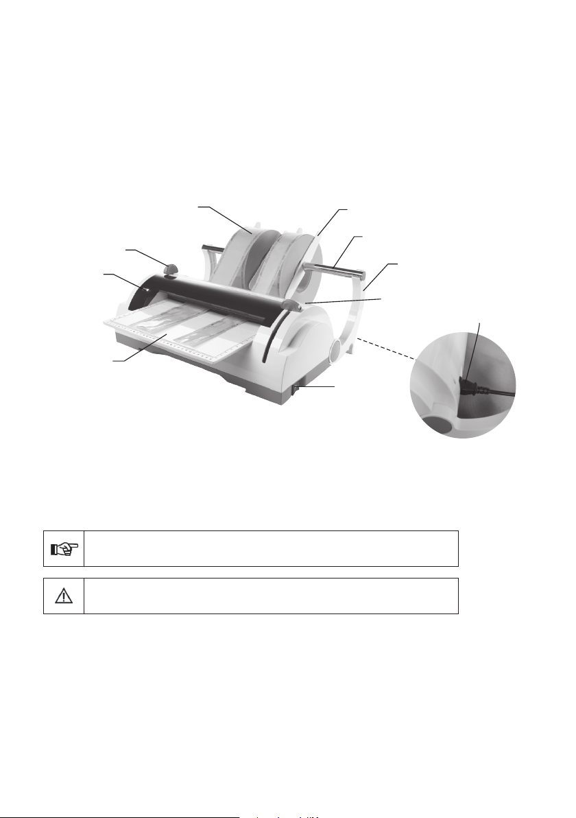
1. Introduction
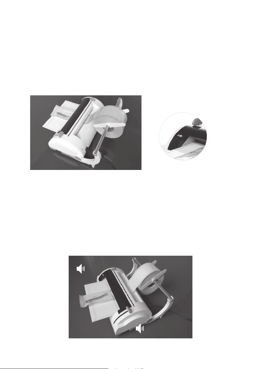
SELINA is the Thermo-sealing machine which fits as a natural complement to the range of steam sterilizer.
It is an elegantly, space-saving designed piece of equipment that is both user-friendly and reliability, even with heavy
use.
SELINA is therefore a useful option for all those users who require professional equipment with an excellent ratio of quality to
price and performance.
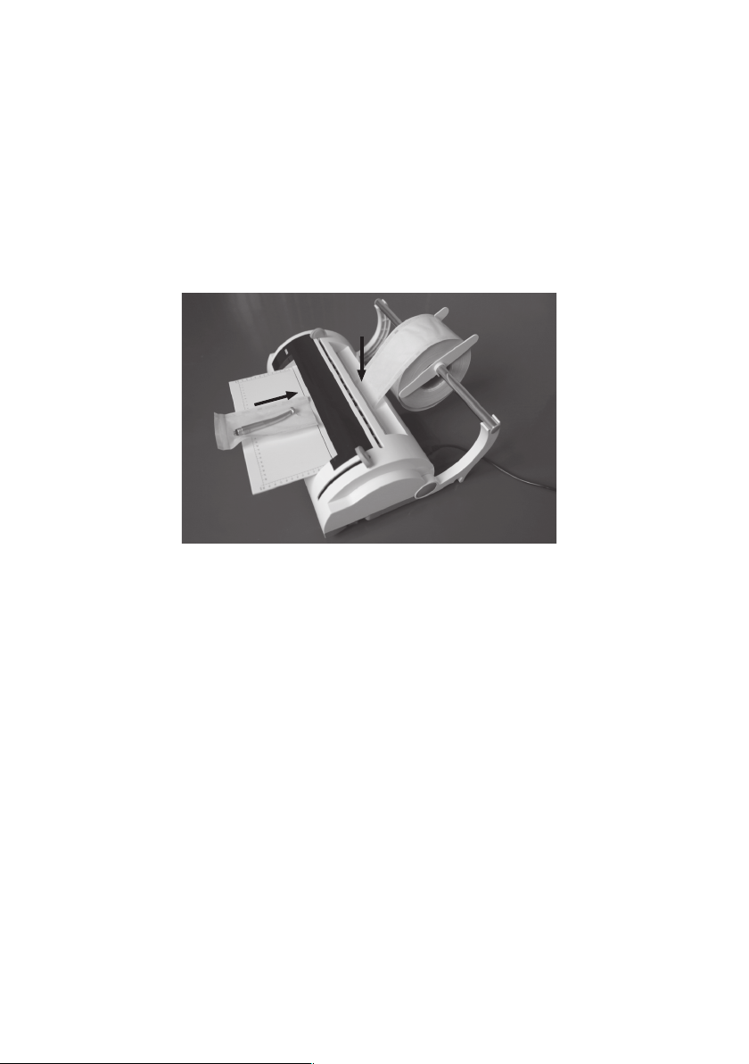
SELINA is an electronically controlled thermo-sealer with a sealing band of 12 mm fit to resist the sterilization processes of the
modern sterilizers featuring fractioned pre-vacuum, and to assure in time the sterility of the packages.
Efficient heat control in the sealing area is achieved thanks to the automatic temperature adjustment, ensuring high
and constant performance.
The solid structure in plastic and aluminum and the ergonomic and minimalist shape help to maintain a high level of
hygiene, weight and overall size and excellent stability during use.
All this with the objective of offering a product suited to the daily needs in the medical/dental area.
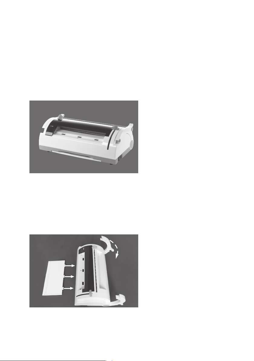
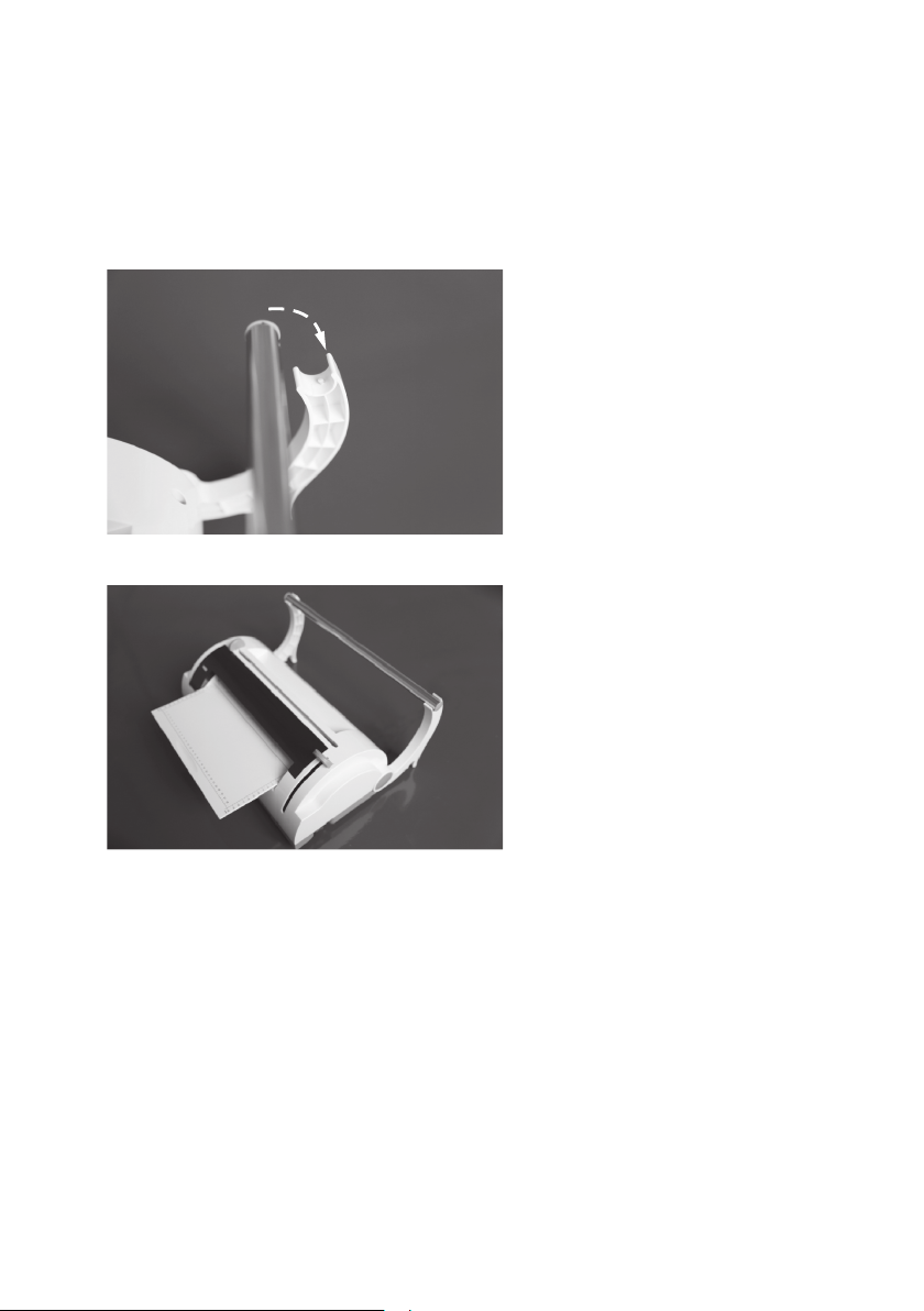
For a good operation of the thermo-sealer the first and essential task is its correct installation; in this way possible
malfunctions or damages to the unit will be avoided.
2

1.
2.
3.
4.
SELINA Thermo-sealing machine
Operation Panel
Reeldividers
Reelholder
5.Paper-stopbarrier
1)Parts description:
Fuse
Powerlead
Operationmanual
9.
6.
7.
8.
Screwsfortwohandles
3
8
5
7
6
4
1
2
3
9

2)Views
Pleaseconnectthemachinewithcorrectpowersupplyaccordingto thedataon thenameplate.
2.Installation:
Therefore please read carefully the notes and warnings reported in the rest of this chapter.
2.1 General precautions
-Install the thermo-sealer on a flat surface, leaving enough room for its operation and adequate ventilation.
-Makes sure that the resting plane is strong enough to support the unit and roll weight.
- Do not install near sinks to avoid contact with water or liquids that could cause short circuits or situations potentially
dangerous for the operator.
- Do not install in humid or poorly ventilated environments;
- Do not install in environment with the presence of inflammable and/or explosive gas or steams;
-Install the unit so that the power supply cable is not bent or pressed along its route up to the mains socket.
THE TECHNICAL SERVICE IS AT YOUR DISPOSAL.TO CLEAR ANY QUESTIONS OR
PROVIDE FURTHER INFORMATION.
THE ELECTRICAL INSTALLATION MUST BE PROVIDED WITH EARTH CONNECTION.
NOTE
WARNING
2
4
Sterilizationpaperreel
WarningLED
Cuttinghandle
Operationpanel
Powerleadoutlet
Weldinghandle
Reeldivider
Reelholder
Holdersupporter
Powerswitch

installation with power rating suitable for the unit consumption and provided with earth connection.
Product preparation
1) Carefully remove the package contents.
2.3
2) Take the operation panel out and insert in the appropriate slots.
And pull back the right and left holder supporters until it reaches to the table.
In compliance with the standing regulations, the unit must be connected to a mains socket of the electrical
2.2 Electrical connection
5

3) Insert the roll holder tube in the supporters, checking that the holes at the end of the tube properly engage in the
teeth present on the supporters.
- Insert the sterilization bag on the roll holder tube.
- Install the roll holder/roll unit on the arm holders (as described in the previous paragraph), positioned in
such a way that the paper belt unrolls downward and with the polypropylene film in view, taking care to
have the sheet pass under the paper-stop barrier.
- Finally, fasten the reel divider.
2.4 Sterilization bag installation
6

1) Preparation
- Verify that the sealing handle is positioned at the highest end of the guide.Switch on the machine via the switch
located at the right side of bottom part.
- The frontal green LED will fl ash. It means preheating.
- Heating resistance is powered and the temperature will increase gradually.
When the ideal level for proper welding is reached, the frontal green LED will remain fixed on.
3. O peration
2) Paper insertion
Have the paper belt pass under the paper-stop barrier and insert it in the rear slot. Then remove it from the front to the
desired length.You can measure the size of sterilization bag which you need before sealing and cutting.
3) Welding an end and cutting
- Lower the sealing handle from position 1 to position 2.
The green LED will flash quickly until sealing has
finished, indicated by an acoustic signal.
- Slide the cutting handle to the opposite end.
- Lift the sealing handle from position 2 to the original position 1.
- The frontal LED will return to a fixed green once again, and the acoustic signal will switch off. The bag is now sealed
on one end.
7
BEEP
BEEP
1
2

4) Bag return and finishing
Put the instruments into the open side of the bag and Insert the unsealed end of the bag in the front slot (F) a few
centimetres, until the end of the bag is aligned with the upper slot (G).
- Perform sealing operations as previously described.
-
8
FG

4. T ec hnical s pec ific ations
4.1 Summary table
Type of sealing :
Voltage
Number of phases
Power supply
Power
Isolation calss
Fuses
200~240V
1
50/60HZ
100W
1/IPXO
2-5x20 F10AL250V
100~120V
1
50/60HZ
100W
1/IPXO
2-5x20 F10AL250V
Environmental conditions for
which the device has been
designed
Interrupter
Dimensions of the seal
Type of sealing
Bipolar
12x300mm
At constant temperature
Intemal use
Altitude up to 3000m
Temperature:+5/+40℃
Relative max.humidity:10%
Installation category(overvoltage category):II
With continuous cycle and constant temperature
Nominal operating temperature
of the heating resistance:180°C
Max sealing length :12 mm
Maximum sealing width:300 mm
Sealable material :Paper /polypropylene film
Max diameter of the roll : 200 mm
Maximum roll width 3: 00 mm
Orientation of the paper /
polypropylene film : Polypropylene fi lm oriented upward
Package dimensions : (L x D x H) 52 x 30 x 21 cm
Net weight : 5 kg
9

The thermo-sealer is equipped with the following safety devices, of which we list a short description along with
their function:
- Mains f us es (see data in the above table)
Equipment protection from internal electrical faults.
Action: break the electrical power supply.
- Automatic o ff o f the h eating c ircuit
If the lever is not lifted back up after sealing has been completed, the heating circuit will be automatically deactivated.
This operation will be indicated by an acoustic signal and intermittent red LEDs.
- Anti- finger c rus hing d es ign
Protection from accidental crushing of fingers during lever movement.
- Automatic S tand-B y S ys tem.
After a period of inactivity of 30 minutes, the machine will go into stand-by mode, switching off the heating resistance.
4.2 Safety devices
This device protects from risks of overheating caused by a failure to switch off the machine at the end of use, creating
significant energy conservation at the same time.
- P rotected c utting knife
Exclusive design with cutting knife totally inaccessible from outside.
10

5.Maintenance
APPENDIX C - MANTEINANCE
GENERALSThe equipment does not need any special care; it is only recommended that the user cleans it periodically.
In all cases carefully follow the procedure detailed below.
In case of replacement of equipment components, request and use ONLY ORIGINAL SPARE PARTS.
CLEANINGCleantheequipmentexternallywithacleanclothdampenedwithwaterandneuterdetergent.
Perfectlydrythesurfacesandremoveanyremainingresistantresidue.
Alwayskeepin mindthefollowinggeneralwarnings:
-Do notsubmittheunitto directwaterjets, underpressureor sprinkling. Anyinfiltrationon
theinternal electricalcomponentscouldirremediablydamageitsoperation;
-Do notuseabrasivesponges, metalbrushes(or otheraggressivematerials) or productsfor
cleaningof metal, bothsolidandliquid.
DANGER
BEFORE PERFORMING ANY MAINTENANCE OPERATION, DISCONNECT THE PLUG OF
THE POWER SUPPLY CABLE FROM THE SOCKET.
ATTENTION
MAKE SURE THAT THE MACHINE HAS COOLED BEFORE ANY MAINTENANCE
OPERATION.
NOTE
- DO NOT USE PRODUCTS CONTAINING ISOPROPYL ALCOHOL(2-PROPANOL,ISOPROPANOL).
- DO NOT USE PRODUCTS THAT CONTAIN SODIUM HYPOCHLORITE(BLEACH).
- DO NOT USE CLEANERS THAT CONTAIN PHENOL
BLADES REPLACEMENT
FUSES REPLACEMENT
The blade must be replaced periodically or when paper cutting problems are noticed.
The fuses are in the fuse holder above the power lead outlet.
-Remove the power lead plug.
-Remove the fuse holder box with a screwdriver.
-Replace the fuse with one of equal value(see appendix A).
11

If Your Thermo-sealer does not work correctly, carry out the following checks before contacting the Technical Service:
6.Troubleshooting
Envelope cutting is difficult.
SUGGESTED SOLUTION
12
The LED is solid red and the
machine is emitting an
acoustic signal
NOTE
SHOULD THE PROBLEM PERSIST, PLEASE CONTACT OUR TECHNICAL SERVICE NETWORK
REPORTING THE THERMOSEALER MODEL AND ITS SERIAL NUMBER.
THESE DATA CAN BE FOUND ON THE FACTORY PLATE PLACES ON THE UNIT REAR.
PROBLEMPOSSIBLE CAUSE
The thermo-sealer does
not switch on.
The plug of the power supply cable is not inserted
inthe outlet.Properly put in the plug.
Lack of power at the power supply outlet.
The magneto thermal switch and/or differential switch
of the installation are OFF.
Mains fuses broken
Check the possible cause of power
failure and try to solve it.
Replace the fuses
(see Appendix C - Maintenance)
Put the switches to ON position.
The LED does not fl ash when
the thermo-sealing machine
is switched on Heating resistance broken. Contact the Technical Support Service
Bag sealing is performed but
the LED remains a fixed green
(instead of red) and no
acoustic signals are heard.
Fault of the end-of-run microswitch.
Insufficient pressure in the sealing area.
Silicon rubber profile damaged.
Resistance does not reach the operating temperature
The Led does not work.
Fault in the electronic card.
Contact the Technical Support Service
Consumed blades.
Contact the Technical Support Service
Operator warning signal
SIGNAL ACTIONCAUSE
The LED is fl ashing greenThe machine is warming up Wait until the machine warms up.
The LED is steady greenThe machine is ready for use
The LED is fast fl ashing greenThe sealing handle has been lowered and the
machine is in use
Wait for the acoustic signal, lift the lever
and remove the bag
The green LED emits a brief
flash every 5 seconds
The machine is in a paused status after a period
of inactivity of 30 minutes.
Lower and lift back up the to rest
normal operation.
handle
The red and green LEDs
flash at the same time
The machine signals the presence of a heating
system problem.
Switch off and retry machine use. If the
signal recurs, contact Technical Support.
The sealing operation has been completed
The machine is on with the sealing lever down
The sealing was lowered before reaching
the proper operating temperature
handleLift the handle
Lift the and remove the baghandle


Other manuals for SELINA
1
Table of contents
Popular Food Saver manuals by other brands

Thermopatch
Thermopatch Auto Maxi NL-33 user manual

Jata electro
Jata electro Premier 2 Instructions of use

Interpack
Interpack IPG UA 262024 SB Operations manual & parts list

P.Lindberg
P.Lindberg FW-3150 Original manual

FoodSaver
FoodSaver Freshsaver reference guide

Kompernass
Kompernass KH 1605 operating instructions