Wow COOLIUS A50 Operation instructions

Original Manual
Service book
A50 / Y50
A/C Service-Unit
Doc.No.: 22302_Rev.04.01

2COOLIUS A50 / Y50

3COOLIUS A50 / Y50
Contents
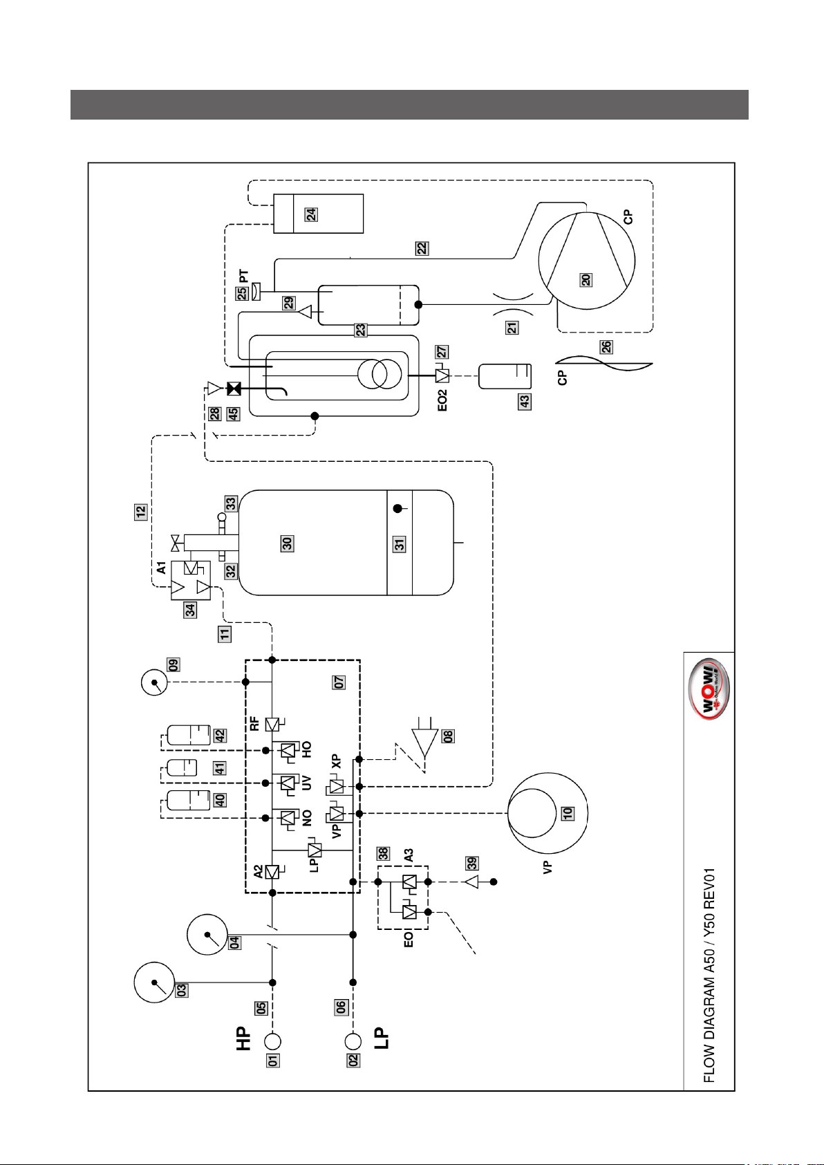
1 Flow diagram ..................................................................................................................................................................................4
1.1 Flow diagram - SPARE PARTS LIST...............................................................................................................................5
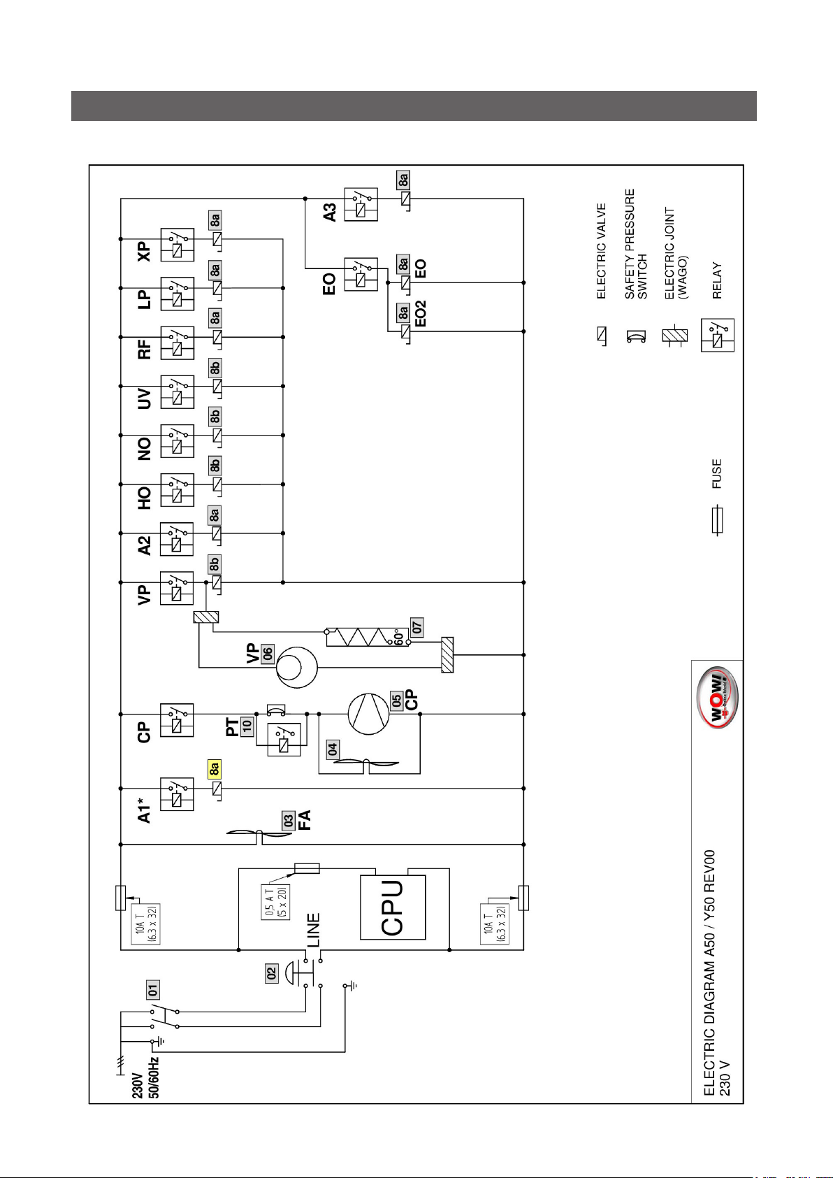
2 Electric diagram ............................................................................................................................................................................7
2.1 Electric diagram - SPARE PARTS LIST..........................................................................................................................8
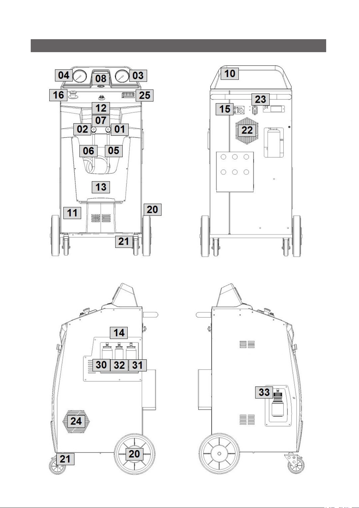
3 Machine .............................................................................................................................................................................................9
3.1 Machine - SPARE PARTS LIST..................................................................................................................................... 10
3.2 Manifold - SPARE PARTS LIST.......................................................................................................................................11
3.3 Other parts - SPARE PARTS LIST................................................................................................................................. 12
3.4 Accessories - SPARE PARTS LIST............................................................................................................................... 12
4 Maintenance................................................................................................................................................................................. 13
4.1 Filter and vacuum pump oil replacement .................................................................................................................... 13
4.1.1 Replacingthelter........................................................................................................................................................ 13
4.1.2 Replacing the vacuum pump oil .............................................................................................................................. 14
4.2 Counter reset (UNLOCK CODE required) .................................................................................................................. 15
5 Calibration..................................................................................................................................................................................... 16
5.1 Refrigerant weight scale .................................................................................................................................................... 16
5.2 Used oil weight scale .......................................................................................................................................................... 17
5.3 Pressure transducer............................................................................................................................................................ 18
6 Mainboard test ............................................................................................................................................................................ 19
6.1 Analysis of the displayed values..................................................................................................................................... 20
6.2 Output test............................................................................................................................................................................... 21
6.3 Phase / Neutral wires pinout ............................................................................................................................................ 23
7 Other passwords ....................................................................................................................................................................... 24
Service Passwords ................................................................................................................................................... 24
Service Report Passwords .................................................................................................................................... 24
Operator Code (OPC) Managing Password.................................................................................................... 24
8 Contact and support.............................................................................................................................................................. 25
8.1 Service Portal COOLIUS-AC.COM .............................................................................................................................. 25

4COOLIUS A50 / Y50
1 Flow diagram

5COOLIUS A50 / Y50
1.1 Flow diagram - SPARE PARTS LIST
N° DESCRIPTION CODE
01 HP SERVICE COUPLING (A50 R134a) 0605115006
HP SERVICE COUPLING (Y50 / Y50A R1234yf) 0605512006
02 LP SERVICE COUPLING (A50 R134a) 0605115001
LP SERVICE COUPLING (Y50 / Y50A R1234yf) 0605512001
03 HP GAUGE (A50 / Y50 / Y50A R134a/R1234yf) 0710175085
04 LP GAUGE (A50 / Y50 / Y50A R134a/R1234yf) 0710145085
05 3 m SERVICE HOSE HP (A50 R134a) 0603015030
3 m SERVICE HOSE HP (Y50 / Y50A R1234yf) 0603019030
06 3 m SERVICE HOSE LP (A50 R134a) 0603010030
3 m SERVICE HOSE LP (Y50 / Y50A R1234yf) 0603013030
07 MANIFOLD (A50 R134a) 0510006008
MANIFOLD (Y50 / Y50A R1234yf) 0510006013
08 ELECTRONIC PRESSURE TRANSDUCER 0712350007
09 INTERNAL VESSEL PRESSURE GAUGE 0710040250
10 VACUUM PUMP 128L 0420023137
11 CHARGE HOSE (A50 R134a) 0603055361
CHARGE HOSE 7/16 UNF O-RING (Y50 / Y50A R1234yf) 0603511041
12 RECOVERY HOSE W/VALVE + ADD.CHECK VALVE (A50 R134a) 0613010401
RECOVERY HOSE 7/16 UNF O-RING (Y50 / Y50A R1234yf) 0603400235
20 COMPRESSOR 5/8 HP 0416190027
21 CAPILLARY 0602099420
22 COMPRESSOR COPPER PIPE 0602005020
23 OIL DISTILLER GROUP (A50 R134a) 0611013054
OIL DISTILLER GROUP (Y50 / Y50A R1234yf) 0611013057
24 MAIN FILTER 0607350344
25 HIGH PRESSURE SWITCH 0703014019
26 COMPRESSOR FAN (D172 230V - LONG CABLE FAN) 0408172053
27 ELECTRIC VALVE GROUP “1A”
(LP / XP / RF / A1* / A2 / EO / EO2 / A3 / GA** / BP** / E3**)0500142050
28 CHECK VALVE - RECOVERY (G1/8 FM) 0501086063
29 CHECK VALVE - OIL DISTILLER (7/16UNF O-Ring MM) 0501071605
30 LIQUID RECEIVER 20L GROUP (A50 R134a) 0612020051
LIQUID RECEIVER 20L GROUP (Y50 / Y50A R1234yf) 0612020059
31 HEAT BELT 0404550058
32 OVERPRESSURE VALVE 0503016045
33 SAFETY VALVE (A50 R134a) 0503144020
SAFETY VALVE (Y50 / Y50A R1234yf) 0503144024
34 INTERNAL VESSEL ADAPTER GROUP (A50 R134a) 0612510009
INTERNAL VESSEL ADAPTER GROUP (Y50 / Y50A R1234yf) 0612511050
38 MANIFOLD FOR PRESSURE TEST 0512200005
39 CHECK VALVE - NITROGEN TEST (G1/8 FF) 0501086062
40 NEW OIL BOTTLE 250 ml (YELLOW PIPE) 0819015250
41 UV TRACER BOTTLE 100 ml 0819015100

6COOLIUS A50 / Y50
42 POE OIL BOTTLE 250 ml (GREEN PIPE) 0819015255
43 USED OIL SEALED BOTTLE 250 ml 0815015250
45 EXPANSION VALVE GROUP NOT AVAILABLE
(*) Applies to R1234yf models only (Y50 / Y50A).
(**) Applies to Y50A only.

7COOLIUS A50 / Y50
2 Electric diagram

8COOLIUS A50 / Y50
2.1 Electric diagram - SPARE PARTS LIST
N° DESCRIPTION CODE
01 MAIN SWITCH 0404230022
02 EMERGENCY SAFETY SWITCH (R1234yf ONLY) 0414020005
03 MAIN FAN (D172 230V - LONG CABLE FAN) 0408172053
04 COMPRESSOR FAN (D172 230V - LONG CABLE FAN) 0408172053
05 COMPRESSOR 5/8 HP 0416190027
06 VACUUM PUMP 128L 0420023137
07 HEAT BELT 0404550058
8a ELECTRIC VALVE GROUP “1A”
(LP / XP / RF / A1* / A2 / EO / EO2 / A3 / GA** / BP** / E3**)0500142050
PISTON FOR “1A” ELECTRIC VALVE
(LP / XP / RF / A1* / A2 / EO / EO2 / A3 / GA** / BP** / E3**)0500142150
8b ELECTRIC VALVE GROUP “1B”
(NO / UV / HO / VP) 0500142075
PISTON FOR “1B” ELECTRIC VALVE
(NO / UV / HO / VP) 0500142175
10 HIGH PRESSURE SWITCH 0703014019
(*) Applies to R1234yf models only (Y50 / Y50A).
(**) Applies to Y50A only.

9COOLIUS A50 / Y50
3 Machine

10 COOLIUS A50 / Y50
3.1 Machine - SPARE PARTS LIST
N° DESCRIPTION CODE
01 HP SERVICE COUPLING (A50 R134a) 0605115006
HP SERVICE COUPLING (Y50 / Y50A R1234yf) 0605512006
02 LP SERVICE COUPLING (A50 R134a) 0605115001
LP SERVICE COUPLING (Y50 / Y50A R1234yf) 0605512001
03 HP GAUGE (A50 /Y50 / Y50A R134a/R1234yf) 0710175085
04 LP GAUGE (A50 /Y50 / Y50A R134a/R1234yf) 0710145085
05 3 m SERVICE HOSE HP (A50 R134a) 0603015030
3 m SERVICE HOSE HP (Y50 / Y50A R1234yf) 0603019030
06 3 m SERVICE HOSE LP (A50 R134a) 0603010030
3 m SERVICE HOSE LP (Y50 / Y50A R1234yf) 0603013030
07 BY-PASS KIT (A50 R134a) 0612400070
BY-PASS KIT (Y50 / Y50A R1234yf) 0612401055
08 INTERNAL VESSEL PRESSURE GAUGE 0710040250
10 TOP COVER 40/50 SERIES 0800700515
11 FRONT PANEL 40/50 SERIES 0800700500
12 A50 STICKER 0807005012
Y50 STICKER 0807005016
13 FRONT POCKET with “WOW!” LOGO 0810411085
FRONT POCKET with “WABCOWÜRTH” LOGO 0810411089
FRONT POCKET with “WÜRTH” LOGO 0810411093
14 A50 / Y50 “PAG/UV/POE” PLASTIC FRAME 0810411050
15 STAR GRIP SCREW for TRANSPORT LOCK 0208002047
16 EMERGENCY SAFETY SWITCH (R1234yf ONLY) 0414020005
20 REAR WHEEL D250 0206001251
21 FRONT WHEEL WITH BRAKE D100 0206001100
22 MAIN FAN (D172 230V - LONG CABLE FAN) 0408172053
23 MAIN SWITCH 0404230022
24 COMPRESSOR FAN (D172 230V - LONG CABLE FAN) 0408172053
25 PRINTER KIT 0413002025
30 NEW OIL BOTTLE 250 ml (YELLOW PIPE) 0819015250
31 POE OIL BOTTLE 250 ml (GREEN PIPE) 0819015255
32 UV TRACER BOTTLE 100 ml 0819015100
33 USED OIL SEALED BOTTLE 250 ml 0815015250

11COOLIUS A50 / Y50
3.2 Manifold - SPARE PARTS LIST
N° DESCRIPTION CODE
01 MANIFOLD (A50 R134a) 0510006008
MANIFOLD (Y50 / Y50A R1234yf) 0510006013
1A ELECTRIC VALVE GROUP “1A”
(LP / XP / RF / A1* / A2 / EO / EO2 / A3 / GA** / BP** / E3**)0500142050
PISTON FOR “1A” ELECTRIC VALVE
(LP / XP / RF / A1* / A2 / EO / EO2 / A3 / GA** / BP** / E3**)0500142150
1B ELECTRIC VALVE GROUP “1B”
(NO / UV / HO / VP) 0500142075
PISTON FOR “1B” ELECTRIC VALVE
(NO / UV / HO / VP) 0500142175
(*) Applies to R1234yf models only (Y50 / Y50A).
(**) Applies to Y50A only.

12 COOLIUS A50 / Y50
3.3 Other parts - SPARE PARTS LIST
N° DESCRIPTION CODE
INTERNAL SUPPORT BUSHING for 4/6 TUBE 0102107704
BRASS OGIVE for 2/4 TUBE 0102137404
INTERNAL SUPPORT BUSHING for 2/4 TUBE 0104999105
O-RING 4,48x1,78 for 1/4 COPPER PIPE 0106178448
O-RING 29,00x2,00 for TRANSPARENT BOWL 0106200029
O-RING 4,42x2,62 for 100L/128L VACUUM PUMP 0106262442
RILSAN PA11 SR HL NEUTRAL PIPE 4/6 0107000164
RILSAN PA11 NEUTRAL PIPE 4/6 0107004006
RILSAN GREEN PIPE 2/4 0107202004
RILSAN PA11 BLUE PIPE 2/4 0107402004
RILSAN BLUE PIPE 6/8 0107406008
RILSAN PA11 RED PIPE 2/4 0107502004
YELLOW PU PIPE 4/6 0107834006
BLUE PU PIPE 4/6 0107844006
CRISTAL PIPE 4/6 0107904006
USB DUST PROTECTION CAP 0400009013
MAINBOARD “A” (PWR) for 40/50 SERIES 0402014051
MAINBOARD “A” (PWR) for 40/50 SERIES - PROTECTED 0402037053
MAINBOARD “B” (DISPLAY) - EUROPEAN VERSION 0402014005
MAINBOARD “B” (DISPLAY) - CYRILLIC VERSION 0402014007
PRINTER PAPER ROLL 0403005840
POWER CORD 3 m (CEE7) 0405270005
CONTROL KNOB (COOLIUS SELECT) 0411210009
LOAD CELL 15KG 0714211019
LOAD CELL 60KG 0714110065
RED / BLUE RINGS for GAUGES 0800101168
KEYBOARD (POLYESTER PANEL) for EUR/CYR DISPLAY 0805045052
MAINTENANCE KIT (FILTER+VACUUM PUMP OIL+GASKETS) 7500100010
3.4 Accessories - SPARE PARTS LIST
N° DESCRIPTION CODE
SERVICE HOSES EXTENSION KIT - ADDITIONAL 3 m (R134a) 2501003134
SERVICE HOSES EXTENSION KIT - ADDITIONAL 3 m (R1234yf) 2501005133
NITROGEN TEST BRACKET KIT 7500270229

13COOLIUS A50 / Y50
4 Maintenance
4.1 Filter and vacuum pump oil replacement
4.1.1 Replacing the lter
NOTE: Always use goggles and gloves!
Contact with the refrigerant can cause blindness and other physical injury to
the user!
1. Beforedismountingthelter,performarecoveryprocessinordertoreducethepressureintheinternal
circuit!
IMPORTANT:Disconnect the plug from the power supply!
2. Usea38mmwrenchtounscrewthelter.
NOTE: Dispose according to local regulations.
3. Lubricate and place correctly the new O-rings.
4. Assemblethenewlter.

14 COOLIUS A50 / Y50
4.1.2 Replacing the vacuum pump oil
NOTE: Always use goggles and gloves!
Contact with the refrigerant can cause blindness and other physical injury to
the user!
IMPORTANT:Disconnect the plug from the power supply!
1. Remove the front cover (4x large head Phillips screws).
2. Unscrew the oil discharge screw Cand wait for the oil to drain.
Thenretthedischargescrew C.
NOTE: Dispose according to local regulations.
3. Unscrewthemuer A.
4. Fill with new oil.
Thecorrectoillevelofthepumpisaroundhalfsightglass(llingcapacityapprox.350ml).
5. Retthemuer A.
6. Reassemble the front cover.
NOTE: Thepicturecouldshowadierenttypeofvacuum
pump.
A Muer
BSight glass to indicate the oil level
CDischarge screw
DDischarge hole
g.001 Vacuum pump
3
1
4
2

15COOLIUS A50 / Y50
4.2 Counter reset (UNLOCK CODE required)
Change lter and vacuum pump oil before resetting maintenance!
NOTE: Only genuine spare parts or their equivalent The use of replacement parts which are not
of equivalent quality may damage the machine!
Go to website www.coolius-ac.com or call the hotline +497940981888188 to get the UNLOCK CODE for
maintenance counter reset.
1. Press START to continue.
2. Use the COOLIUS SELECT to enter the maintenance
UNLOCK CODE obtained from www.coolius-ac.com.
Whendone,conrmbySTART.
• If the UNLOCK CODE is wrong, repeat the step 2.
• If the UNLOCK CODE is right, go to step 3.
3. Press X(CANCEL)keytoconrm.
4. Press again X(CANCEL) keytoconrmandresetthe
counter.
Maintenance reset successfully completed.
Get UNLOCK CODE
register:
BB111111
www.coolius-ac.com
A*******
A
34567890 BCDEFGHIJK
Counter reset.
Confirm by “X”
min. ///
Counter reset.
Confirm again!

16 COOLIUS A50 / Y50
5 Calibration
1. Select SERVICE and type password: 311299
The display shows:
2. Turn COOLIUS SELECT to select among:
• Refrigerant weight scale
• Used oil weight scale
• Pressure transducer
3. Press ENTERtoconrmthechoice.
5.1 Refrigerant weight scale
Unload the refrigerant weight scale
1. Unload the scale by moving the star grip screw of the
transport lock to “safety position” (lift the knob and move
it to the left).
2. When done, press ENTERkeytoconrmthesafetypositionandwait!
Load the refrigerant weight scale
3. Load the scale by moving the star grip screw of the
transport lock back to the “working position” (move the
knob slightly up and to the right, then fully down).
4. When done, wait a few seconds then press ENTERkeytoconrmand
wait for screen change!
Select:
Refrig. weight scale
Unload weight scale
(safety position)
g.002 Safety position
Load weight scale
(working position)
g.003 Working position

17COOLIUS A50 / Y50
Place the sample weight
5. Dismount the top cover (remove the 4 screws).
6. Place a known sample weight (minimum 2 kg, suggested 5 kg) on the
center of the scale bracket (as shown in the picture).
7. When done, wait a few seconds then press ENTERkeytoconrm
and wait for screen change!
Set the sample weight value
8. Turn COOLIUS SELECT to set the value of sample
weight.
9. When done, press STARTtoconrm.
Calibration completed.
5.2 Used oil weight scale
Unload the used oil weight scale
1. Unload the scale by removing the used oil bottle.
When done, wait a few seconds then press ENTER key
toconrm.
2. Press ENTERkeyagaintoconrmandwait!
Place the sample weight
3. Place a known sample weight (minimum 50 g) on the
used oil weight scale bracket.
When done, wait a few seconds then press ENTER key
toconrmandwaitforscreenchange!
Place the sample
weight on the scale.
Set the sample
weight value.
g.
Unload used oil
scale!
Confirm by “ENTER”
used oil scale
unloaded!
Place the sample
weight on the scale.

18 COOLIUS A50 / Y50
Set the sample weight value
4. Turn COOLIUS SELECT to set the value of sample
weight.
5. When done, press STARTtoconrm.
Calibration completed.
5.3 Pressure transducer
IMPORTANT: The quick coupler must be assembled on the service hoses and the gauges must
show 0 (zero) pressure!
1. Press START to begin the calibration of pressure trans-
ducer.
2. The vacuum pump starts and perform a short vacuum
phase.
After a few seconds, the displayed value (ADC points)
must be lower than 250.
3. When the vacuum pump stops and the display shows:
Remove the LP service connector (low pressure side
quick coupling) from the BLUE service hose, then press
ENTERtoconrm.
Wait for screen change!
4. Turn COOLIUS SELECT to set the atmospheric pres-
sure (ex. 1010 mb)
When done, press STARTtoconrm.
5. Wait the end, then press STOP to exit.
Calibration completed.
Set the sample
weight value.
g.
Confirm by “START”
Wait!
xx
Remove the LP
connector from the
service hose.
Set the atmospheric
pressure value (abs)
mb. 0

19COOLIUS A50 / Y50
6 Mainboard test
IMPORTANT NOTE: Machine disconnected from any A/C system or refrigerant tank!
Check that both HP and LP gauges show zero pressure!
1. Select SERVICE and type password: 228482
The display shows:
(1) CONTROLLED OUTPUT
(2) REFRIGERANT SCALE Net compensated value.
(3) REFRIGERANT SCALE Analog to digital converter points.
(4) USED OIL SCALE Analog to digital converter points.
(5) USED OIL SCALE Net value compensated.
(6) PRESSURE TRANSMITTER Analog to digital converter points.
(7) PRESSURE TRANSMITTER Absolute pressure compensated value.
(8) TEMPERATURE External probe [tenths of °C].
NOTE: If the external temperature probe is not connected to the machine, the value shown on the display
shall not be considered as reliable.
(9) TEMPERATURE Mainboard “B” (Display) [tenths of °C].
(10) TEMPERATURE Mainboard “A” (PWR) [tenths of °C].
(11) KEY ID number.
KEY IDENTIFICATION NUMBER
Thenumberidentiesthepressedkeyasdescribedbelow:
0 No key pressed
2 ENTER key (the ENTER key activates the output indicated on the display, read the instructions be-
fore use)
4 STOP key (not visible)
8 START key
16 X(CANCEL) key
32 RIGHT key
64 i(INFO) key
128 LEFT key
Test 0 TA209 TB208
CP TE163
1240 21 940
8850000 4000 7560
1
2
3
4 5
11 10
9
8
7
6

20 COOLIUS A50 / Y50
6.1 Analysis of the displayed values
Pressure Transmitter:
With the correct calibration, dismount the LP quick coupler.
The ABS (Absolute) Pressure value compensated shall be roughly the ABS atmospheric pressure -10 / -15
mb.
Blow compressed air into the LP service hose (blue):
The display has to show an increase of the ABS Pressure value and of the ADC points.
Disconnect the Pressure Transmitter connector from the mainboard “A” (PWR).
The ABS Pressure value shall be 1 and the Pressure Transmitter ADC point should be roughly 1.
Refrigerant Scale:
The shown value is the net value (Total–Tare Weight Value)
The ADC point value is the total value.
Therstfournumbersshallbestable,thelastthreecanoat.
The values displayed are directly linked to the weight on the scale.
As a reference, consider that a calibrated scale with all the containers empty shall show roughly 8900000
points.Valuesthataresignicantlydierentfromthereferenceindicateapossibleproblem.
To check quickly if the weighing system is working correctly it is enough to press on the load cell (scale
bracket): both the ADC points and the net value compensated shall increase.
Used Oil Scale:
The value shown is the net value (Total–Tare Weight Value)
The ADC point value is the total value.
The values displayed are directly linked to the weight on the scale.
CPU board temperature °C
The temperature is shown in tenths of Celsius degrees.
The displayed value is the temperature of a sensor mounted on the board.
This manual suits for next models
1
Table of contents
Other Wow Service Equipment manuals