WQA WaterSTATION PuR100-7 Operation manual

#92673 Rev. 1/11
PuR100-7
Installation, Operation, Service Record and Warranty

ii
What Does the Water Quality Association (WQA) Gold Seal
Mean to a Consumer?
Safe drinking water is very important to you and your family. Many municipalities meets the minimum requirements to
provide drinking water, most do not meet the recommended health and safety goals set by governmental agencies nor
they have control over the decreasing water quality as it travel through all distribution systems and household plumbing.
Hence it is important to treat water at your household with the help of water treatment and filtration products. It is important
to know that the water treatment and filtration products “Do what they say they will” and the plumbing components that
touch your water “don’t introduce harmful contaminants.”
With so many products out in the market how can you know that which ones do the job safely and which ones don’t? You
need an easy to recognize trusted seal approval on the products that are safe to use and will perform as advertised. There
is a mark that tells you at a glance all you need to know “The Water Quality Association Gold Seal”. The Gold Seal on any
drinking water product is exactly what’s certified and this delivers cleaner and safer water.
Since 1959, the water quality association Gold Seal certification program has been testing and certifying products that filter
or touch the water you drink.
It guarantees two critical aspects of consumer safety, that the filtration and treatment products perform as expected and
the plumbing products at your home aren’t hazardous to water quality.
It is a well known program among the consumer and regulatory bodies everywhere.
Visit www.wqa.org to view the online listing of products that have earned Gold Seal.
Vist http://www.wqa.org/goldseal/movie/2010/wqa_wb/index.html to view a short video on WQA Gold Seal Program.

INTRODUCTION
Thank you and congratulations on making a smart decision to invest in a WaterSTATION.
You have joined an elite group of water enthusiasts who demand only the best when it comes to their health and the health
of their family.
In order to fully enjoy your system, please read the users manual thoroughly before use and please use this manual for
future reference.
Since your satisfaction is our priority, feel free to contact our service experts should you have any questions. You may
reach us toll free at 1-866-874-2532.
We are proud of our product and we trust that our strict devotion to the highest quality assurance standards will provide
you with years and years of clearer, treated, great tasting water.
By now, you have probably already opened the box to survey the contents. Please take a few moments to review this
manual before proceeding with the installation and use of the system. Some important items to review are as follows:
• Checkallcomponentsforanydamagecausedinshipment.Also,takeaquickinventoryofallitemssupplied
to ensure none are missing. A checklist in the next section will assist you with identifying these items.
• EnsurethattheWaterSTATIONandstoragetankwilleasilyfitintothedesiredlocation.ThisWaterSTATION
and tank needs to be removed for regular maintenance, so good accessibility is an important tip to keep in
mind.
• Readallwarningscontainedwithinthismanual.
The water produced by the ‘WaterSTATION’ can be used for many purposes around the home.
• Drinking Water - keep container of WaterSTATION water in the fridge to be able to enjoy the cleaner,
fresher taste. Alternatively, take it directly from the tap.
• Ice Cubes - use WaterSTATION water to fill ice cube trays. Ice cubes made from WaterSTATION water are
typically clearer and better tasting than ice made from plain tap water.
• Automatic Ice Makers - a water line from the WaterSTATION system can be plumbed to refrigerators with
automatic icemakers. Additional accessories required to complete this connection are not included. Please
consult the refrigerator’s owner’s manual on this installation.
• Kettles and Coffee Makers - plain tap water eventually causes films and scale in these devices that is
difficult to clean. WaterSTATION water is very low in dissolved minerals content, greatly reducing the
chance of scale buildup.
• Cooking - use WaterSTATION water for boiling pasta, rice or any other recipe that calls for water in the
instructions.
• Washing Fresh Fruit & Vegetables - prevent tap water minerals from being deposited onto food to
maintain freshness.
• Family Pets - Allow your dog or cat to enjoy the same purified water you do.
• Irons. Steamers & Portable Humidifiers - prevent mineral buildup in household appliances that use water
and eventually build up with scale when using plain tap water.
Now you can relax and enjoy the benefits of great tasting water supplied by your WaterSTATION. Remember that good
quality water is important to maintaining a healthy lifestyle. You can also feel good about the money you have saved by
installing your own WaterSTATION instead of dealing with the expense and hassle of bottled water delivery and also the
impact of the water bottles to the environment.
Simply the best!
1
Printed on
Recycled Paper

2
TABLE OF CONTENTS
System Safety Guidelines ..................................................................................3
SuppliedItemChecklist......................................................................................4
Maintenance Requirement .................................................................................5
Installation Requirements...................................................................................6
Installation Steps ................................................................................................8
Activating the System.......................................................................................17
Sanitization Procedures....................................................................................18
Parts List and Drawing for PuR100-7 WaterSTATION ....................................20
WaterSTATION Flow Diagram .........................................................................22
Troubleshooting Guide .....................................................................................23
Service Record and Warranty ..........................................................................24

3
SAFETY GUIDELINES
•ReadallstepsandguidescarefullybeforeinstallingandusingyourWaterSTATION.Followallstepsexactlytocorrectly
install.
•Thissystemmustbeinstalledinaccordancewithapplicablecity,provincial,stateandlocalplumbingcodes.
•To ensure this system continues to operate at its optimum level, it is necessary to have a routine maintenance and
replacement schedule. Please check the filter replacement frequency in the system specification section and maintenance
section of this manual. Frequency at which filters must be changed will depend on quality of feed water supply and level
of system usage. The replacement of the water treatment components of this unit is critical to maintain the performance
of the system.
•Thissystem shouldnot beused wherethe wateris microbiologically unsafe or with water of unknown quality without
adequate disinfection before and/or after the filter. Please refer to the conditions use section in this manual.
•Topreventpersonalinjury,completelyrelievethesystempressurebeforereplacingorinstallingfiltersandmembrane.
•Donotplacethissystemwhereitwillbeexposedtothefreezingand/ordirectsunlight.Pleaserefertoconditionsforuse
section in this manual
NOTE: The Reverse Osmosis system contains a replaceable treatment component, critical for the effective reduction of
total dissolved solids, and that product water shall be tested periodically to verify that the system is performing properly.
SYSTEM SPECIFICATIONS
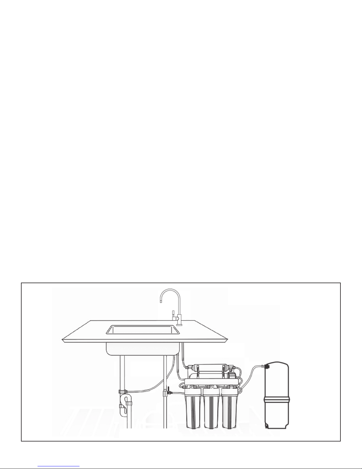
WaterSTATION Item #: 940270
Model #: PuR100-7
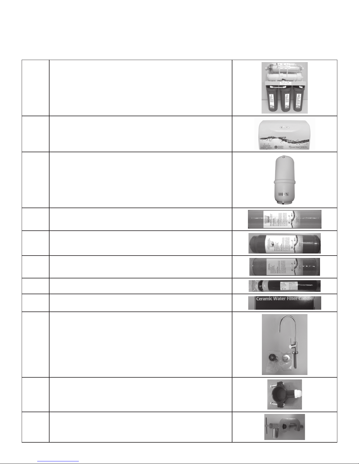
Item # Stage Filter / Type Capacity
92621 First Stage
(Pre Filter) Sediment Filter 5 Micron Sediment Filter,
10" Length
Reduces suspended particles in water such as dirt or
sediment. Reduces the particles 8 times smaller than
what the naked eye can see.**
4,440 L
92622
(Pre Filter)
Granular Activated
Carbon Filter 10 Micron GAC Filter, 10" Length Reduces chlorine from the water to protect TFC
membrane.** 9,250 L
92623
(Pre Filter) Carbon Block Filter 10 Micron Carbon Block Filter,
10" Length Reduces taste & odor from water.** 9,250 L
92624
TFC Membrane 100 TFC* GPD Membrane,
10" Length Reduces TDS from water.** 37,000 L
92625 Fifth Stage
Inline Carbon Filter 10 Micron Carbon Filter,
10" Length Reduces taste and odor from the water.** 5,550 L
92626 Sixth Stage
Inline Calcite Filter Calcite Filter, 10" Length Increase pH of water‡. Add minerals to improve the
5,550 L
92627
Ceramic Filter 0.5 Micron Ceramic Filter,
10" Length
an added particulate reduction to 0.5 micron.**
7,400 L
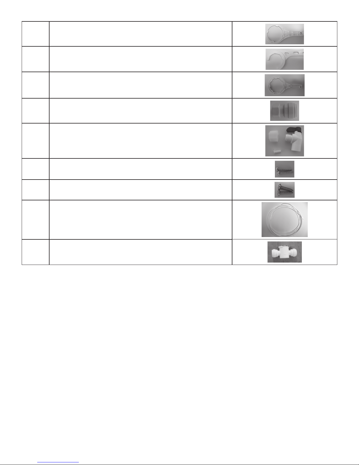
92657 Plastic 3.8 Gallon / 14.4 L Storage Capacity Storage for Product Water -
Chemical Parameters Max mg/L
Community / Private Chlorinated / Non-Chlorinated Hardness (CaCO3) < 350 (20 gpg)
PH Range 3.0 - 11.0 Iron (Fe) < 0.1
Maximum TDS Level < 2000 ppm Manganese (Mn) < 0.05
Turbidity < 1.0 NTU 2S) 0.00
Maximum SDI < 4.0 Residual Chlorine (Cl2) < 2.0
Pressure 50 - 100 psi †† NTU - Nephelometric Turbidity Unit
SDI - Silt Density Index
Temperature 4 - 38ºC
CONDITIONS FOR USE
†† Booster Pump is required if the inlet pressure of the water is below 50 psi.
100GPD. Nominal product water ratings are based on the following
conditions: Supply TDS of 250 ppm conditioned tap water, 50 psi, 77ºF, pH 8 and 15% recovery with
outlet to atmosphere
99%. Rejection percentages are dependent on the supply conditions and the
substance being measured
This system is not intended to be used for the treatment of water that is microbiologically unsafe or of
unknown quality without adequate disinfection before or after the system.
The performance of a reverse osmosis membrane is highly dependent upon pressure,
temperature and TDS. The actual volume of product water and rejection percentage will vary with
differences and the test conditions that membrane ratings are based upon.
‡ The processed water from TFC membrane has low pH and is aggressive and tends to dissolve
substances with which it is in contact.
* TFC refers to reverse osmosis membrane constructed from a THIN FILM COMPOSITE

4
SUPPLIED ITEM CHECKLIST
Out of the box, your new WaterSTATION should be supplied with the following items. If any items appear to be missing,
contact your dealer. Please check all components for any damage that may have been caused by shipping.
1 WaterSTATION Module
2 Shroud
3Storage Tank
4 First Stage Sediment Filter
5SecondStageGACCarbonFilter
6ThirdStageCarbonBlockFilter
7FourthStageTFCMembrane
8SeventhStageCeramicFilter
9 Air Gap Faucet
10 DrainSaddleValve(QuickConnect)
11 InletSaddleValve(QuickConnect)

5
MAINTENANCE REQUIREMENTS
Service Requirements - To insure the system operates at its optimum level, certain routine maintenance must be
performed. Frequency of maintenance performance will depend on feed water quality and level of system usage.
CLEAN:Eachtimefiltersarereplaced
SANITIZE: At least once a year and each time membrane is replaced
Recommended Service Intervals - Replace filters as required or based on capacity listed on page 3 depending on feed
water quality. Replace membrane as required based on periodic TDS rejection tests.
12 Module Sump Wrench
13 MembraneHousingCapWrench
14 CeramicFilterHousingWrench
15 Faucet Adapter Fitting
16 TankValve(includingplasticnutandtubeinsert)
17 ScrewforWallMountingofWaterSTATIONModule(2)
18 ScrewtoattachShroudtoWaterSTATIONModule(2)
19 Tubing(3/8”White(18FT),1/4"White(12FT)
20 Inline1/4”SafetyShut-offBallValve(QuickConnect)

6
INSTALLATION REQUIREMENTS
TOOLS
The following tools may be necessary, depending on each particular installation:
SYSTEM LOCATION
Your WaterSTATION may be installed under a sink, in a basement or other location, depending on available space. Do
notinstallunitwheretemperaturesfallbelowfreezing;otherwise,damagewillresult.Connectiontoanicemakershould
also be considered for optimum performance.*
* It is recommended to install an icemaker to a maximum of 30 to 40 feet from the system with a 3/8” tubing.
Guidelines for component placement are as follows:
•Faucetshouldbeplacednearthesinkwheredrinking/cookingwaterisnormallyrequired.A2”flatsurfaceisrequiredto
mount the faucet if an existing hole for a second faucet is not available. The thickness of the mounting thickness should
not exceed 1-1/4”.
•Storagetankmaybeplacedwhereitisconvenient,withintenfeetofthefaucet.Underthesinkorinanearbycabinet
are excellent choices. If tank is located further than ten feet from the faucet, use 1/2’ tubing to reduce pressure drop.
Full tanks may weight more than thirty pounds, so a sturdy shelf is required.
•WaterSTATIONunitmaybemountedoneithersideofthesink,inacabinetorheatedbasementwithnearbyaccessto
a potable, cold water line. Feed water connection is accomplished with a self-piercing feed water saddle valve. Locate
thisassemblyasclosetotheWaterSTATIONunitaspossible.Connecttoapotable,coldwatersupplylineonly.
Note:ConditionedwaterispreferredsinceitwillextendthelifeofyourTFCmembrane.
•Drainconnectionisaccomplishedusingawastewatersaddlevalvewhichisdesignedtofitaroundastandard1-1/2”
ODdrainpipe.Thedrainsaddlevalveshouldalwaysbeinstalledabove(before)thetrapandontheverticalor
horizontal tailpiece.
•Donotinstallthedrainsaddlevalvenearagarbagedisposal;otherwise,pluggingofthewastewaterlinemayoccur.If
discharging into a utility sink or standpipe, an air gap must be provided (Air gaps must be 1” or greater above the floor
rim).Theairgapinthissystemisbuiltinthefaucet.Pleaserefertothediagrambelow.
Note: Plumbing codes may require the use air gaps. Please check with your local municipality.
•DonotconnecttheWaterSTATIONdrainlinetothedishwasherdrainlineduetothefactbackpressuresmycausethe
air gap to overflow.
SITE PREPARATION
Installing dealers may want to speak with customers
in advance and ask them to clean under the sink to
save time. If a basement installation is advisable,
check area to determine if extra fittings or hosing
arerequired.Uponarrival,itisagoodideato
check the condition of all plumbing for potential
leaks and advise customer so there will be no
misunderstandings in the event leaks occur.
•3/8”variablespeedelectricdrill:1/8”
& 1/2” bits
•1-1/4”porcelainholecutter(ifhole
forsecondfaucetisnotprovided)
•Centerpunchandhammer
•1-1/4”woodbit
•Concretedrillbits
•Phillipsheadandflatblade
screwdrivers
•Adjustablewrench
•Crescentwrench
•Teflontape
•Plastictubecutter
•Airpressuregauge(lowpressure)
•Airpump(hand)
Drain Line from
Air Gap

7
INTER-COMPONENT CONNECTIONS
Connections between cold water supply line, RO Module, storage tank, product water faucet, and drain line are accomplished
using plastic tubing and push-together quick-connect type fittings.
PLASTIC TUBING
1. Cut tube ends square and straight. Do not deform
tube (i.e., cause tube to compress its diameter so it
is no longer round).
2. Make sure outer surface of tube is clear of marks or
scratches for a length equal to twice tube diameter.
This allows "O" ring to seat properly against tube.
3. Avoid sharp changes in direction when routing
tubing. Sharp turns cause tubing to flex and deform,
which reduces its flow capacity and may increase
lateral stress on the fittings, causing leakage.
QUICK-CONNECT FITTINGS
Fittings consist of two parts: a Body and a colored collet
and symbol. Collet color and symbol corresponds to
tubing to be used at that connection (Figure 2.A.).
1. To install a tube, push it through Collet until it seats
firmly at bottom of fitting (Figure 2.A and 2.B.).
2. To remove a tube, push and hold Collet against
Body while pulling tube out (Figure 2.C.).
A. Push tube through Collet into Body. B. Tube must seat firmly at bottom of
fitting.
C. Push Collet against Body to release
tube.
Figure 2: How to Use Quick-Connect Fittings
INSTALLATION REQUIREMENTS CONT’D
OTHER COMPONENTS FUNCTION
Bracket to Mount the WaterSTATION Module on the wall or inside the under sink cabinet
Automatic Shut-Off Valve sense when the storage tank is full and closes the water supply to conserve water
Faucet to dispense product water when needed
Inlet Saddle Valve is connected to the cold water line to supply water to the WaterSTATION system
Drain Saddle Valve is connected to the drain to remove reject water from the WaterSTATION system
Tubing supplies feed and reject water
Shroud to cover the WaterSTATION module from the top
Module Sump Wrenchtoremovethe1st,2ndand3rdStageSumpConvenientlywhenreplacingorinstallingPre-Filters
Membrane Housing Cap WrenchtoremovethecapeasilywhenreplacingandinstallingTFCMembrane
Ceramic Filter Housing WrenchtoremovethecapeasilywhenreplacingandinstallingtheCeramicFilter
Faucet Adapter Fitting to be installed in the faucet for easy connection to WaterSTATION Module
Tank Valve to be installed on the Storage Tank for connection to the WaterSTATION Module
INTER-COMPONENT CONNECTIONS
Connectionsbetweencoldwatersupplyline,WaterSTATION Module, storage tank, product water faucet, and drain line
areaccomplishedusingplastictubingandpush-togetherquick-connecttypettings.
PLASTIC TUBING
1.Cuttubeendssquareandstraight.Donotdeformtube
(i.e., cause tube to compress its diameter so it is no
longerround).
2. Make sure outer surface of tube is clear of marks or
scratches for a length equal to twice tube diameter. This
allows “O” ring to seat properly against tube.
3. Avoid sharp changes in direction when routing tubing.
Sharp turns cause tubing to flex and deform, which
reduces its flow capacity and may increase lateral stress
on the fittings, causing leakage.
QUICK-CONNECT FITTINGS
Fittings consist of two parts: a Body and a colored collet
andsymbol.Colletcolorandsymbolcorrespondstotubing
tobeusedatthatconnection(Figure2.A.).
1.Toinstallatube,pushitthroughColletuntilitseats
firmlyatbottomoffitting(Figure2.Aand2.B.).
2.Toremoveatube,pushandholdColletagainstBody
whilepullingtubeout(Figure2.C.).

8
INSTALLATION STEPS
INLET SADDLE VALVE INSTALLATION ON COPPER TUBE
CAUTION:Thisinletsaddlevalveisnotdesignedforinstallationonflexlinetubing.
1. CAUTION: If no shut off valve is installed under sink,
close main water valve during this Installation. Locate
shut off valves on water lines under sink. To identify
hot supply pipe and cold supply pipe, turn both faucets
on and let water run. As water flows, hot water pipe
becomes noticeably warmer.
2. CAUTION: Do not install feed water assembly on hot
water line.
Turn off cold water supply by closing shut off valve.
Drain line by opening sink faucet. Some mixing type
faucets may require hot water supply be shut off as well.
NOTE: All instructions refer to components shown in
Figure 3 unless otherwise noted.
3. CAUTION: Do not turn valve handle before or while
installing saddle-tapping valve. Make sure piercing lance
does not protrude beyond rubber gasket before installing
valve.
Assemble saddle-tapping valve assembly on tube.
a. Hold back plate against tube.
•3/8”coppertubingusebackplatesmallerradius.
•1/2”coppertubing,usebackplatelargerradius
b. Hold valve saddle against tubing in a position directly
opposite back plate.
c. Tighten screw enough so valve saddle and back plate
are held securely against tube.
d. Rotate assembly so tubing connection is aligned
toward WaterSTATION Module feed port.
e. Tighten screw firmly. Do not crush tube.
4.Connectsourcewaterfeedtubingtovalvebodyusing
compression fitting.
a.Slidenutandsleeveontotubing(inthatorder).
b. Install insert into plastic tubing.
c. Install tube with insert and sleeve into valve body.
d. Thread compression nut onto valve body, tighten.
5. Turn saddle-tapping valve handle clockwise until it is
firmly seated and piercing lance is fully extended.
6. CAUTION: Supply line is pierced and valve is closed.
Do not open valve until system is activated. Turn on cold
watersupply.Checksaddle-tappingvalveinstallationfor
leaks. Allow water to run from faucet for a few minutes
to clear any debris in the line caused by installation.
NOTE: If flow from sink faucet is reduced, clean faucet
aerator.
Figure 3: Inlet Saddle Valve Assembly Installed on 1/2”
CopperTubing
7. Trim ¼” white tube to desired length. Install ¼”
white tube into ¼” white collet as shown in the inter-
component connection.
ADDITIONAL POINT OF USE CONNECTION
NOTE:Icemakerstypicallyuse1/4”tubingasfeedline.Useareducingunionforthisconnection.
NOTE: Reduce the 3/8” Line to 1/4” as close as possible to the additional point-of use device to minimize flow loss.
1. To connect an additional point of use (icemaker, extra
faucetinwetbarand/oranotherusefortreatedwater),
place a “tee” connector in 3/8” white line between faucet
and WaterSTATION Module.
2.Connect“tee”topoint-of-usewith3/8”whitetubing.
Connecttubingtopoint-of-use.Connectorrequirements
are based on type of delivery device i.e., a typical
icemaker uses 3/8” x 1/4” reducing device.
HOUSEHOLD COLD WATER LINE
SMALLER RADIUS
TIGHTENING
SCREW
REVERSIBLE
BACK PLATE
TUBING TO MODULE
VALVE BODY
VALVE HANDLE
LARGER RADIUS
STEM SEAL NUT

9
DRAIN SADDLE VALVE INSTALLATION
Prior to proceeding it is important to inspect the condition of drain pipes to make sure they are not thin and frail.
Drain saddle valves are designed to be installed on standard 1-1/2” OD drain pipe. Install drain saddle valve above
(andbefore)thetrapandontheverticalorhorizontaltailpiece.Neverinstalladrainsaddlevalveclosetotheoutletofa
garbage disposal or plugging of the WaterSTATION drain line may result.
Procedures
1. Position threaded half of drain saddle valve at selected
location and mark for the opening.
2. Drill 3/8’ hole at mark through one side of pipe.
3. Position both halves of drain saddle on drain pipe so
threaded opening lines with hole.
4. Secure drain saddle clamp on valve with bolts and nuts
provided. (Do not over tighten and make sure there is
equalspacebetweensaddlehalvesoneachside.)
STORAGE TANK INSTALLATION
1. Hand-tighten the ball valve onto the WaterSTATION storage tank.
CAUTION: Do not over-tighten ball valve as this may strip threads or compromise the “O” ring seal.
2. Slide compression nut over 3/8” white tubing.
3.a.Makesuretoinstallthe“INSERT”inthe3/8”whitetubingbeforetighteningthenutoftheballvalve.
b. Push 3/8” white tubing into the ball valve as far as possible.
4. While holding the 3/8” white tubing in the ball valve, hand-tighten the compression nut onto the ball valve.
5.Connect3/8”whitetubingtotheteefittingontheWaterSTATION.
NOTE: Withthestoragetankempty,ensuretheair-cellpre-charge(7psi)issettomanufacturersinstructionsmarked
ontank.Useahandpowerairpumptotopupifnecessary.
WARNING: Never use an air compressor to fill air cell of the WaterSTATION storage tank.
Never tamper with the air valve located at the bottom of the tank.
DRAIN PIPE
DRAIN CLAMP
FRONT FLARE
LINE TUBE
IMPORTANT
Ball Valve
3/8”

10
PRODUCT WATER FAUCET SITE PREPARATION
Refer to Faucet Installation Instructions (Page 6) for site location and mounting hole specifications.
Primary considerations for site selection are convenience of use and an open area under sink. An existing 7/8”
Sink Hole will also accommodate metal faucets with air-gap connections. Always check underside of selected
location for obstructions.
PORCELAIN/ENAMEL OVER STEEL
OR CAST IRON SINKS
1. CAUTION: A heavy duty, variable speed drill motor
with a spring-loaded porcelain drill set (Figure 6) is
strongly recommended for this procedure.
CAUTION: The plastic sleeve supplied on pilot drill
(Figure 6.A) is to be positioned on drill bit against drill
chuck. This prevents chuck from contacting
porcelain after pilot hole has been completed.
NOTE: Practice on discarded sinks to familiarize
yourself with operation of porcelain cutter kit.
Using carbide tipped bit with plastic sleeve (Figure
6.A.), drill pilot hole completely through porcelain and
metal underneath.
2. CAUTION: Avoid high motor R.P.M. during initial
penetration of porcelain, as high drill speed will cause
excessive chipping.
Place spring-loaded porcelain saw (Figure 6.B.) into
drill chuck. Make sure pilot guide is inserted tightly.
Insert pilot guide into pilot hole. Push down gently on
drill motor to apply light pressure to porcelain surface.
Start drill motor turning as slowly as possible.
After initial cut has started, motor speed may be
gradually increased. The cut may require three to
four minutes to complete. Going faster could result in
excessive chipping. Be sure a complete ring has
been cut through porcelain to material underneath.
3. Place finish hole saw (Figure 6.C.) into drill chuck.
Make sure pilot guide is inserted tightly. Insert pilot
guide into pilot hole. Begin cut using a slow speed
and light pressure until porcelain (inside ring cut in
Step 2) has been penetrated to material underneath.
4. Remove saw from hole and clean all debris from
porcelain surface. Re-insert saw into hole and cut
through remaining material.
5. Installation hole is ready, install faucet.
TILE COUNTER TOP
1. Follow procedures detailed in section labeled
"Porcelain/Enamel Over Steel" (substitute "tile" for
"Porcelain" in instructions).
STAINLESS STEEL SINK
1. Use a center punch to make a small indentation to
mark center of desired location.
2. Drill a pilot hole with a 1/8" metal drill bit, then enlarge
hole with a 9/16" metal drill bit.
3. Complete hole size by using a 1 1/4" chassis punch.
4. Installation hole is ready, install faucet.
A. PILOT DRILL
B. SPRING LOADED PORCELAIN SAW
C. FINISH HOLE SAW
Figure 6
INSTALLATION STEPS CONT’D
PRODUCT WATER FAUCET SITE PREPARATION
Primary considerations for site selection are convenience of use and an open area under sink. An existing 7/8” sink
hole will also accommodate metal faucets with air-gap connections. Always check underside of selected location for
obstructions.
PORCELAIN/ENAMEL OVER STEEL OR CAST IRON
SINKS
1. CAUTION: A heavy duty, variable speed drill motor with
aspring-loadedporcelaindrillset(Figure6)isstrongly
recommended for this procedure.
CAUTION: The plastic sleeve supplied on pilot drill
(Figure6.A)istobepositionedondrillbitagainstdrill
chuck. This prevents chuck from contacting porcelain
after pilot hole has been completed.
NOTE: Practice on discarded sinks to familiarize
yourself with operation of porcelain cutter kit.
Usingcarbidetippedbitwithplasticsleeve(Figure6.A.),
drill pilot hole completely through porcelain and metal
underneath.
2. CAUTION: Avoid high motor R.P.M. during initial
penetration of porcelain, as high drill speed will cause
excessive chipping.
Placespring-loadedporcelainsaw(Figure6.B.)intodrill
chuck. Make sure pilot guide is inserted tightly. Insert
pilot guide into pilot hole. Push down gently on drill
motor to apply light pressure to porcelain surface. Start
drill motor turning as slowly as possible.
After initial cut has started, motor speed may be
gradually increased. The cut may require three to
four minutes to complete. Going faster could result in
excessive chipping. Be sure a complete ring has been
cut through porcelain to material underneath.
3.Placefinishholesaw(Figure6.C.)intodrillchuck.Make
sure pilot guide is inserted tightly. Insert pilot guide
into pilot hole. Begin cut using a slow speed and light
pressureuntilporcelain(insideringcutinStep2)has
been penetrated to material underneath.
4. Remove saw from hole and clean all debris from
porcelain surface. Re-insert saw into hole and cut
through remaining material.
5. Installation hole is ready, install faucet.
TILE COUNTER TOP
1. Follow procedures detailed in section labeled “Porcelain/
EnamelOverSteel”(substitute“tile”for“Porcelain”in
instructions).
STAINLESS STEEL SINK
1.Useacenterpunchtomakeasmallindentationtomark
center of desired location.
2. Drill a pilot hole with a 1/8” metal drill bit, then enlarge
hole with a 9/16” metal drill bit.
3.Completeholesizebyusinga7/8”chassispunch.
4. Installation hole is ready, install faucet.

11
PRODUCT WATER FAUCET INSTALLATION
New Faucet Installation
Refer to Faucet Site Preparation, selection on the previous
page.
Replacement Faucet Installation
Verify size of existing hole is 7/8”.
1. Refer to faucet installation diagram shown here.
2. a. Install 3/8” white tubing from Installation Kit onto
largerhosebarb(3/8”barb).
b. Install 1/4” white tubing onto smaller hose barb (1/4”
barb).
3. a. Insert the 3/8” white tube into the mounting hole.
b. Insert the 1/4” white tubing into the mounting hole.
4. Lower faucet into mounting hole and place
faucet over hole.
5. Install split washer, spacer, faucet washer, and nut onto
faucet nipple below sink and snug them up. Be sure
to properly align faucet before tightening. Do not over
tighten.
6. Install faucet connector. Apply food grade teflon tape,
packaged with faucet, onto faucet nipple. Install 3/8”
white tube into faucet connector.
7. Trim 3/8” white tube to desired length. Install 3/8” white
tube into WaterSTATION module.
8. CAUTION: White 3/8” tube connecting product water
faucet to drain saddle must run vertically (or as closely
aspossible)withnosharpbendsorloops.
REMEMBER:
Connectairgapoffaucetasfollows:
a.Connect1/4”whitetubingfromtheWaterSTATION
module to the 1/4” barb of the air gap.
b.Connect3/8”whitetubingfromthedrainsaddlevalve
to the 3/8” barb of the air gap.
Lockwasher
Locking Nut
Spacer
Split Washer
7/8” Mounting Hole
Counter Top
Escutcheon
O-ring
Air Gap
Window
Faucet
3/8”White Tubing
to Drain Saddle Valve
1/4”White Tubing from
WaterSTATION Module
3/8” Barb
Faucet Adapter
3/8”White Faucet Tubing
Connected to RO Module
1/4” Barb
ConnectedtoWaterSTATIONModule

12
INSTALLATION STEPS CONT’D
INSTALLATION OF WATERSTATION MODULE
INSTALLATION OF FILTERS
1.Unscrewsumps1,2and3fromtheWaterSTATIONmodulewiththehelp
of the wrench provided in the installation kit. Install sediment filter in sump
1, granular activated carbon filter in sump 2 and carbon block filter in
sump 3.
Sump #3
Carbon Block Filter
(Part #92623)
Sump #2
GAC Carbon Filter
(Part #92622)
Sump #1
Sediment Filter
(Part #92621)
INSTALLATION OF TFC MEMBRANE
1. Disconnect the hose on the end of the membrane housing end cap.
2.UnscrewtheendcapoftheTFCmembranehousingwiththehelpofthewrenchprovided.Slidethewrenchfromthe
left-hand side onto the cap.
3. Hold the membrane upside down, cut the plastic bag at the bottom.
4. The bottom tip of the membrane must sit firmly in the protruding female socket inside the membrane housing.
5. Without touching the membrane, slide it into the membrane housing and discard the plastic bag. With your thumb or
the palm of your hand, push the membrane all the way into the housing.
Important: Do not force, and ensure that the membrane is not protruding from the housing.
6. Replace the membrane housing end cap and do not over tighten.
7.Pushthetubingbackinthequickconnectfitting.Ensurethetubingsareallthewayin.
Disconnect
the hose
Membrane
Housing Cap
Cut the bag of the TFC
membrane at the bottom
Connect
the tubing
TFC
Membrane

13
CONNECTING COMPONENTS
NOTE:ALLTHETUBINGFROMTHEWATERSTATIONMODULENEEDSTOBEROUTEDTHROUGHTHEHOLES
LOCATEDONTHEBRACKETSOTHATTHESHROUDINSTALLATIONBECOMESEASIERATTHELASTSTEP.
Locate the following sticker on the WaterSTATION Module. The following section will help you identify them. “TO
WATERINLET”,“TOTANK”,“TOFAUCET”&“TODRAIN”
2.Connectthe3/8”whitetubingfromthestoragetanktotheWaterSTATIONModule.Thelocationofthisconnection
ismarketby“TOTANK”stickerontheTeeoftheWaterSTATIONModule.Cutthetubeifrequired.Routethiswhite
tubing through the hole located at the WaterSTATION bracket as shown below.
from Storage Tank
Cap
tubing to
storage
tank routed
through the
hole of the
bracket
1.Connectthe¼”whitetubingfromtheinletsaddlevalvetothe90degreeelbowofsump1oftheWaterSTATION
Module.Cutthetubeifrequired.Thelocationofthisconnectionismarkedby“TOWATERINLET”stickerinthe
WaterSTATION Module. Route the white tubing through any of the holes located at the WaterSTATION bracket.

14
3.Connectthe3/8”whitetubingfromtheairgapfaucettotheWaterSTATIONModule.Thelocationofthisconnectionis
markedby“TOFAUCET”stickerontheceramichousingcap.Cutthetubeifrequired.Routethiswhitetubingthrough
the hole located at the WaterSTATION bracket as shown below.
Ceramic Filter
Faucet
the bracket
4.Connectthe1/4”whitetubingfromtheairgapbarbofthefaucettotheWaterSTATIONModule.Thelocationofthis
connectionismarketby“TODRAIN”stickerontheflowrestrictor.Cutthetubeifrequired.Routethiswhitetubing
through the hole located at the WaterSTATION bracket as shown below.
Flow
Restrictor
To Drain Sticker
gap hose of the faucet
Flow
Restrictor
through the hole in the bracket
INSTALLATION STEPS CONT’D
CONNECTING COMPONENTS CONT’D

15
DRAIN FLUSH VALVE - AdrainflushvalvehasbeeninstalledintheWaterSTATIONsystemforthecleaningofTFC
membrane
For water usage, keep the drain flush valve closed. For cleaning purposes, open the drain flush valve based on the
frequency determined by the feed water quality and recommended by the maintenance service personnel
WARNING: Keep the drain flush valve closed at all the times and open it only when the TFC Membrane cleaning
is required.
Drain Flush Valve OPEN for TFC membrane cleaning Drain Flush Valve CLOSED for potable water use
NOTE: Before installing the ceramic filter, the drain flush valve needs to be open with inlet water ON and the
TFC membrane needs to be flushed for 15 minutes. This will remove fines from the pre-membrane carbon filter.
FLUSHING THE POST CARBON FILTER (NO CERAMIC OR CALCITE FILTERS INSTALLED)
1.Closethedrainflushvalveandletthestoragetankfillwithwater.
2.Closetheshutoffvalveofthestoragetank.
3. Remove the outlet connection from the post-carbon filter and discard one storage tank water by turning on the storage
tank’s shut-off valve.
4. Re-connect the tubing to the post-carbon filter.
Remove
tubing as
shown
Calcite Filter
Post-carbon Filter
Post-
carbon
Filter
Discard one storage
tank of water.

16
INSTALLATION OF CERAMIC CARTRIDGE
Before installing the ceramic cartridge, the WaterSTATION system needs to be flushed with water in order to get rid of
carbon fines from post-membrane carbon filter. Discard one storage tank of water before calcite filter. Depending on
pressureofinletwater,thesystemneedstobeflushedfor24hours(withcalcitefilterinstalled).Discardtwotanksof
storage tank water.
INSTALLATION OF CERAMIC CARTRIDGE
1.Unscrewtheendcapoftheceramichousingwiththehelpofthewrench
provided.
2.Unpacktheceramicfilterandhandleitverygently.
WARNING – the ceramic filter is very fragile and requires gentle
handling
3. Install the O-ring provided with the ceramic cartridge on to the thread of
the ceramic cartridge
4. Screw the ceramic filter on to the threads of the ceramic housing cap.
5. Install the ceramic housing cap with the help of the wrench provided. Do
not over tighten.
Ceramic
Housing
Cap
Ceramic
Filter
O-ring
(comes with
Flush the WaterSTATION system for one hour and allow the system to stand unused for a further 24 hours. Then
flush the system for 10 minutes.
INSTALLATION OF SHROUD
1. Install the shroud over the top of the Water STATION module. Put two screws supplied at the bottom of the shroud.
Screws are to
be installed at
the bottom of
the bracket.
Attach the manual to the bracket for future reference.

17
Flush Type Required for Procedure Time
Pre-CarbonFilterFlush Flushcarbonnesfrompre-carbonlters Drain Flush Valve ON and NO
CeramicFilterInstalled.
15 Minutes
Pre-Carbon(without
CalciteFilter)Flush
Flushcarbonnesfrompost-carbonlter Drain Flush Valve OFF and
NOCeramicorCalciteFilter
Installed. Tank Valve Open.
Discard one tank of
storage water
Post-CarbonFilterFlush Flushcarbonnesfrompost-carbonlters Drain Flush Valve OFF and NO
CeramicFilterInstalled.Tank
ValveClosed.
24 Hours
Post-CarbonFilterFlush
&CalciteFilterFlush
Flushcarbonnesfrompost-carbonlters Drain Flush Valve OFF and NO
CeramicFilterInstalled.Tank
Valve Open.
Discard two tanks
of storage water
CeramicFilterFlush FlushCeramicFilter Drain Flush Valve OFF,
CeramicFilterInstalled.
1 Hour
No Flush-Idle IdleTimeforCeramicFilter DoNotUsetheUnit,Inlet
Water Supply should be OFF.
24 Hours Idle Time
Fine Flush FlushextranesfromCarbonandCeramicFilter Drain Flush Valve OFF,
CeramicFilterInstalled.
10 Minutes
ACTIVATING THE SYSTEM
Before activating the WaterSTATION system, make sure that the following steps are performed:
1.15minutesofTFCmembraneflushing(withdrainflushvalveON).
2.Discardonestoragetankofwater(withdrainflushvalveoff,tankvalveopen)andnoceramicandcalcitefilters
installed.
3.24hoursofTFCmembraneflushing(withdrainflushvalveOFFandceramicfilternotinstalled).
4.Discardtwotanksofstoragetankwater(withdrainflushvalveoffandceramicfilternotinstalled).
5.1hourofTFCmembraneflushingwithceramicfilterinstalled.
6. Let the system stand unused for 24 hours.
7. Flush the system for 10 minutes.
CAUTION: Make sure all water supply lines, drain lines, and fittings are secure and free from leakage.
1.Opensourcewatersupplyvalve.Closeproductwaterfaucet.Checkforleakage.
2. Turn tank valve one-quarter turn counter- clockwise to open valve (handle should be in line with tubing as it enters
connection).
3.Confirmsystemisproducingwater.Modulewillbesendingrinsewatertodrain.
4. Open product water faucet and let water flow until all air has been expelled from system.
5.Closeproductwaterfaucet.In30minutes,checkconnectionsforleaksandcorrectifnecessary.
Icemaker/Extra point of use: Checkconnectionsonthesesupplylinesforleaks.
6. Allow storage tank to fill overnight.
7. WARNING: DO NOT USE THE FIRST TWO FULL STORAGE TANKS OF WATER. THE FIRST FEW GALLONS
OF WATER WILL CONTAIN CARBON FINES AND MILKY APPEARANCE DUE TO CARBON AND
CERAMIC FILTER.
Keepthedrainflushvalveclosed.Discard(todrain)firstTWOfulltanksofwaterbyopeningproductwater(andextra
point-of-use)faucetuntilwaterflowstops,thenclosefaucet.Thiswillflushsanitizingsolutionfromsystem.
Icemaker: Let tray/bin fill with ice cubes. Discard all ice cubes. This flushes sanitizing solution from lines to
icemaker.
UseTDSMetertoverifytheTFCmembraneisfunctioningproperly.
8. System is ready to use. Should there be any aftertaste or odor to water or ice cubes, repeat Steps 6 and 7.
DO NOT USE THE FIRST TWO STORAGE TANKS OF WATER
Allow storage tank to fill overnight. Dispense this water to drain.
This process removes factory-installed sanitizing solution from the entire system and sends it to drain.
This process also sanitizes fittings and tubing used during installation.
FLUSHING INSTRUCTIONS

18
CLEANING, SANITIZING, AND CARTRIDGE REPLACEMENT PROCEDURE
1. Mix mild cleaning solution of dish soap and clean
potable water in plastic bowl.
2. Closefeedwatersupplyvalveandopenproduct
waterfaucet.Emptystoragetankandrelievesystem
pressure. Verify tank valve is open.
Icemaker: Transfer ice cubes from bin/tray to clean
freezer container for storage until procedure is done.
3. CAUTION: Useairhandpumptoavoiddamaging
tank. Verify product water valve is open before
proceeding.
Checkproductwaterstoragetankairprechargeusing
alow-pressuregauge(e.g.0-15or0–30psi).Air
valve is located on tank base. Pre-charge should be 40
kPa(7psig)withtankemptyandtankvalveopen.
4. CAUTION: Do not attempt to remove filter housings
until water flow stops. This reduces pressure inside
the system so housings may safely be removed.
CAUTION: Additional point-of-use devices (i.e.,
icemakers)mayusefiltersalongtheirsupplyline.
Remove any filter or treatment device installed
between module and device before proceeding.
Remove each filter/membrane housing by turning it
counter-clockwise. Remove each filter cartridge as its
housing is removed. Discard filters.
IFMEMBRANEISPERFORMINGSATISFACTORILY:
Proceed to Step 5.
IFMEMBRANEISDEPLETEDORFOULED:
Discard it and go to Step 7.
5. CAUTION:Usesanitaryrubberglovesforthis
procedure to avoid contaminating sanitizing solution,
filters, or membrane. Wear gloves whenever cleaning/
sanitizing system components or handling new filter/
membrane cartridges.
Cleanmembraneouterwrapwithwashclothand
cleaning solution. Do not immerse membrane in
solution. Do not scrub membrane wrap with abrasive
cleaners. Rinse membrane well with clean potable
water.
6. Place membrane into clean plastic bag, close bag.
7. Remove filter/membrane housing “O” rings and wash
them with cleaning solution. Rinse them well with clean
potable water. Inspect them for damage (i.e., nicks,
scratches).Replacedamaged“O”rings.
8. Cleanfilterhousingsinsideandoutside,withwashcloth
and cleaning solution. Do not use abrasive materials.
9. Rinse housings with clean potable water.
10. Inspect filter housing “O” ring groove area for damage.
Replace damaged components.
11. Place a small amount of “O” ring lubricant over surface
of filter/membrane housing “O” ring. Install “O” ring into
filter housing groove.
WARNING: WEAR SAFETY GLASSES WHILE
PERFORMING THIS PROCEDURE.
READ “WARNINGS” INFORMATION ON BLEACH
CONTAINER BEFORE USING CONTENTS.
HANDLE SANITIZING SOLUTION CAREFULLY. AVOID
CONTACT WITH UNPROTECTED AREAS.
12. CAUTION:Excessiveconcentrationsofbleachwill
damage plastic and rubber components. Rinse all
parts that contact bleach thoroughly with clean
potable water.
Mixsanitizingsolutionof1.5ml(1/3teaspoon)of
householdbleachand3.8L(1gallon)ofclean,potable
water in the bucket. Mix solution well.
13. CAUTION: Tighten filter housings by hand only. Do
not use tools as they will over-tighten and damage
housings. Take care not to cut or pinch o-rings.
Add236ml(onecupor8oz.)ofsanitizingsolutionto
each filter housing and install them onto the manifold
(donotinstallfiltersormembraneatthistime).Tighten
each filter housing by hand only.
MAINTENANCE PROCEDURE PREPARATION
RECOMMENDATIONS:HAVEALLEQUIPMENTANDREPLACEMENTCOMPONENTSONHANDANDREADY
BEFOREBEGINNINGPROCEDURE.ACLEANWORKAREAANDEQUIPMENTAREESSENTIALTOPROPERLY
CLEANAND/ORSANITIZETHESYSTEM.(i.e.,CLEANHANDS,TOOLS,WORKSURFACE,ANDCONTAINERS)
EQUIPMENT NEEDED:
•Safetyglasses •Rubbergloves,sanitary •WashCloth,CleanandLint-free
•Liquiddishsoap •Plasticstoragebag •ManualAirPump
•Plasticbucket •Plasticbowl •“O”ringLubeFDAApproved
•Householdbleach-UnscentedOnly(51/4%sodiumhypochlorite)
Table of contents
Popular Water Filtration System manuals by other brands

Oase
Oase BioPlus Series operating instructions

Wisy
Wisy WFF 150 instructions

Paramount Fitness
Paramount Fitness Paralevel Startup manual

Excalibur Water Systems
Excalibur Water Systems Value Zentec Hybrid Air Capsulate installation manual

Grunbeck
Grunbeck MB9 Operation manual

Atlas Filtri
Atlas Filtri DP BIG F DUO quick start guide