Wren Turbines 44 TurboProp User manual

W
W
WR
R
RE
E
EN
N
N
4
4
44
4
4
T
T
TU
U
UR
R
RB
B
BO
O
OP
P
PR
R
RO
O
OP
P
P
I
I
IN
N
NS
S
ST
T
TA
A
AL
L
LL
L
LA
A
AT
T
TI
I
IO
O
ON
N
N
A
A
AN
N
ND
D
D
O
O
OP
P
PE
E
ER
R
RA
A
AT
T
TI
I
IN
N
NG
G
G
M
M
MA
A
AN
N
NU
U
UA
A
AL
L
L
Copyright Wren Turbines Ltd
September 2008

Wren 44 TurboProp Users Manual. Copyright Wren Turbines Ltd February 2008 Page 2
WREN 44 TurboProp Manual
Congratulations on your purchase of the new miniature Wren 44 TurboProp gas turbine engine.
This manual has been prepared to help you set up and safely operate your engine. If you encounter any
problems then please consult this list first and if you cannot find a solution please get in touch with us. The
engine is simple to prepare and use but certain precautions must be observed for your safety and others
near you – see safety notes.
Included in the manual is a problem checklist to help solve any problems you may encounter in operation.
Please remember, although small and seemingly harmless the engine is definitely not a toy and must be
treated with utmost care and consideration to your own safety and others around you. The manual also
contains sections on the individual components of the installation and operation, refer to these for more
detailed information.
Contents:
3 Introduction
4 Package contents
5 Weights and Measures
6 General description of the two-shaft drive system
9 Detail description of the turboprop unit and ancilliaries
13 Safety issues, do's and don’ts
14 Warranty, service and repair
15 Performance
16 Propeller selection and balancing
17 Fuel consumption/duration
20 Installation Do’s and Don’ts
22 Wiring and Plumbing Schematic
35 Installing the system components
23 Connecting the system components
27 Setting up the ECU
28 ECU Failsafe function
29 Preparing for running
31 Running the unit
36 Starting and running, problem checklist
34 Flying the unit
35 After running
37 Storage
38
Basic servicing
Front Cover Pictures - Acknowledgments:
Front page upper – the first 44 Turbo-Prop prototype installed in a Pilatus “Porter” for gliding towing, by kind
permission from Lucien Gerard, Luxemburg.
Front page middle - the 2
nd
prototype Wren 44 Turbo-Prop installed in a Top Flight “P51 Mustang”, by kind
permission from Lucien Gerard of Luxemburg.
Front page lower left – the first production Wren 44 Turbo-Prop installed in a Graupner “Taxi”. By kind
permission from owner, Barrie King.
Front Page, lower right – Wren 44 Turbo-Prop installed in a YAK88 from ExtremeFlightRC, flown by Jeannot
Behm.
Wren Turbines Ltd. Unit 19, Century Park Network Centre, Manvers, Rotherham,
South Yorkshire. England.
Tel. 01709 877439. Fax 01709 875935 Email: info@wrenturbines.co.uk

Wren 44 TurboProp Users Manual. Copyright Wren Turbines Ltd February 2008 Page 3
The new Wren 44 TurboProp
Introduction
This new development from the highly popular Wren 44 Gold thrust engine stable, has been long awaited. It
has built on the success of the Wren 54 Turboprop which has now been on sale in various forms since 2002.
The engine has been the outcome of a long R&D programme primarily concerned with maximising the
performance and minimising the aggravation of installing and operating, allowing the flier to get on with the
business of flying.
We have been careful to keep the weight of the unit down but have not compromised stiffness which has
shown itself to be a major concern for turbo-props. The engine is not modified for use in this application
apart from a small hole drilled in the case to add a lubrication port, enabling the full perfomance to be used
in driving the propeller, producing performance usually described as “awesome” by all those witnessing it.
The gearbox assembly is strongly built to withstand many hours of operation and is designed to be
lubricated with a small fuel take-off from the engine. All this is automatic and the user need do no more than
put fuel into the tank, charge batteries and go fly!
We have tried hard to produce a compact high power to weight engine capable of filling the gap left by the
noisy medium to large I/C engine, and the existing range of turbo-prop engines now becoming available.
Most of these are really only suited to large aircraft around 2.5 to 3m (8’ to 10’) wingspan, which has
implications for cost, transport and suitability of flying field. There are a large number of airframes already
available in the 2m (6’) size that are attractive for conversion to turbo-prop for the reasons outlined above
and are suited for the average club flier. The low installed weight around 2kg compares well with equivelent
2-cycle engines and helps to keep the wing loading sensible.
Noise is becoming a major concern and the 44 turbo-prop enjoys a remarkably low noise figure, rivalling
electric models in many cases. The noise is predominantly propeller noise and with the smooth application
of torque and total absence of power pulses enables a very low perceived noise level to be achieved.
The Wren 44 Turboprop enjoys the same highly responsive engine as the Wren 44 Gold thrust version so
the absolute minimum throttle lag can be appreciated by those keen on prop hanging and the usual
aerobatics. The small engine size enables the fuel consumption to be described as “stingy” so no need for
lugging a big fuel bottle around.
Importantly, the engine is already well established so you are not buying an unproven design. Parts and
service is readily available and the hundreds of Wren 44 Gold customers across the world will testify to the
longevity and ease of use of this world-beating engine.
Above all - Enjoy!
From all the team at Wren Turbines Ltd
February 2008
Special thanks to:
Lucien Gerard, a good friend and colleague of all at Wren
Turbines, who was the first customer to build a Wren 54
turboprop back in 2002 that still flies in an Embrear Tucano
and encouraged this development from the start.
Lucien supplied aircraft for flight testing the 1
st
and 2
nd
Wren
44 turbo-prop prototypes and undertook all the test flying. His
generous help and feedback has greatly assisted and
encouraged us to push this unique development forward into
successful production.
Thank-you.

Wren 44 TurboProp Users Manual. Copyright Wren Turbines Ltd February 2008 Page 4
The Wren 44 TurboProp package contains the following:
1) Wren 44 TurboProp Engine
2) Fuel pump
3) Autostart ECU (Engine Control Unit)
4) ECU data display terminal
5) ECU Battery (2-cell LiPo)
6) Propane canister valve
7) Fuel solenoid
8) Propane solenoid (with attached adjustable flow control valve)
9) Propane tank and one way valve
10) Brass two-part quick-release propane connector
Lay out the engine and its support equipment on a clean surface and identify all the components.
Weights and Measures
Weights:
Power unit complete with cables 1710g (3-3/4 lbs)
Fuel pump 88g (3oz)
Valves (Propane and Fuel) 65g (2-1/4oz)
ECU (Engine Control Unit) 35g (1-1/4oz)
LiPo battery 7.4v, 1500mAh 80g (2-3/4oz)
All up weight 1978g (4lb 5-3/4oz)

Wren 44 TurboProp Users Manual. Copyright Wren Turbines Ltd February 2008 Page 5
Measurements:
Overall engine length 365mm (14-3/8”)
Overall width across standard exhausts 245mm (9-1/2”)
Engine mounting flange to prop driver 160mm (6-5/16”)
Mounting flange diameter 110mm ( 4-5/16”)
Mounting bolt circle 100mm (3-15/16”)
Mounting bolt M3 (or 4-40 UNC), 6-off, length to suit
Propshaft thread M8 x 1mm pitch
Propshaft length 40mm (1-1/2”)
Max propeller thickness 30mm (1-3/16”)
Prop driver diameter 40mm (1-1/2”)
Prop nut size 12mm A/F
Glowplug JP PowerPlug type F
A couple of templates for making the cutout for the engine mounting are included at the rear of
the manual, to full scale. Simply cut out, stick to the front of the firewall and cut through.
The template looks like this (reduced version for show
only):
GlowPlug
Viewed from
Propeller end
TOP
6 off, Ø3
(1/8")
Ø85
An determined look on the face of Lucien Gerard as he taxis out the 2
nd
prototype turboprop in the Top Flight “P51 Mustang” for handling
checks, ouside Wren Turbines HQ. Nov 2007

Wren 44 TurboProp Users Manual. Copyright Wren Turbines Ltd February 2008 Page 6
General description of the Wren 44 two-shaft drive system
The Wren 44 TurboProp is the worlds smallest commercial 2-shaft turbo-prop engine. It is
designed for use in miniature aircraft applications in place of an I/C engine. It is generally suited
to aircraft up to 25kg (55lb) in all up weight and will replace I/C engines of around 80cc (4.8cu
inch). The engine runs on standard kerosene and is supplied in full auto-start configuration.
What is a two-shaft system?
The two shaft system means there are two independant shafts running within the unit. The first
shaft is contained within the engine end of the unit and rotates at very high speed (up to
195,000rpm) with just a small compressor wheel and turbine attached at each end. This engine
end of the unit generates a flow of gas at high pressure and volume, and its operation is exactly
as a small gas turbine engine. It fulfills the function of what we call a gas generator. If a nozzle is
attached to the outlet of the engine it imparts a slight squeezing of the gas into a high velocity jet
for producing jet thrust and is the configuration for a thrust engine. For a gas generator version of
the engine, instead of squeezing the gas through a nozzle it is redirected by a vane assembly to
turn a 2nd turbine wheel mounted on the 2nd stage shaft. This is driven round in the gas stream
and this rotation drives the input shaft to the gearbox and onwards to the propeller. This 2nd
turbine is much larger in diameter than the 1st stage and correspondingly runs much slower - up
to only 90,000rpm - still far higher than any 2-stroke or electric motor could achieve, but at a high
torque level. The energy given up by the gas driving the 2nd stage turbine drastically reduces the
speed of the exhaust gas with the result than only a small residual thrust remains from the
exhaust outlets.
What happens if I stall the propeller?
When operating from long grass or in a nose-over situation that causes the propeller to stall, the
gas generator will continue to function normally with little ill-effects. On releasing the propeller
from its stalled form it will spin back up to it's normal running speed. This should be born in mind
when retrieving the model from the long grass or nose-over situation - for you or your helper to
keep well clear of the propeller whenever the gas generator is running.
What sort of gearbox is required?
The modest rpm levels generated by the 2nd stage turbine (by gas turbine standards) enable an
suitable reduction to be contained in a small gearbox, the ratio of which is chosen to suit the
operational needs of the load driven. In the case of the 44 TurboProp the reduction is 9:1 and this
gives a propeller shaft speed range of 6,000-9,000rpm. The 2nd turbine has a wide operating rpm
range and may be slowed with high load or allowed to speed up with low load without upsetting
the 1st stage, therefore the choice of propeller is not at all critical, providing it presents enough
load for the system (see warning below). The main criteria for propeller choice being the type of
plane the unit is fitted to (scale, aerobatic, sports etc).
What are other two shaft examples?
Other Wren applications that use the same 2-shaft system are the Wren 44 Marine variant that
has a 2.3:1 reduction gearbox for an output speed of 25,000-40,000rpm and the Wren 44 Heli
unit with a reduction of 4:1 and output speed range of 12,000-20,000rpm.
WARNING - it is most important that there must always be some load on the output shaft
as otherwise the 2nd stage turbine will be running unrestrained and may easily speed up
beyond it's safe running speed, even when the gas generator is running at only a modest
rpm. This means the unit should never be run without a suitable propeller fitted.

Wren 44 TurboProp Users Manual. Copyright Wren Turbines Ltd February 2008 Page 7
What is the effect of airspeed on the engine?
Once the aircraft is in the air the propeller rpm will increase as its load reduces with forward
speed. An rpm increase of 10-15% can be expected in the air so always choose a propellor that
keeps the output speed below 9,000rpm. It is this increase in propeller rpm in the air which gives
the turbo-prop powered aircraft a high airspeed capability and shows a definite edge over it's I/C
engine counterpart. I/C engines have a more limited unloaded speed capability, as it can result in
the engine mixture strength "leaning out" which can cause engine damage. By contrast the turbo-
prop will enjoy running cooler as the propeller speed unloads leading to longer life and reduced
loading on critical components.
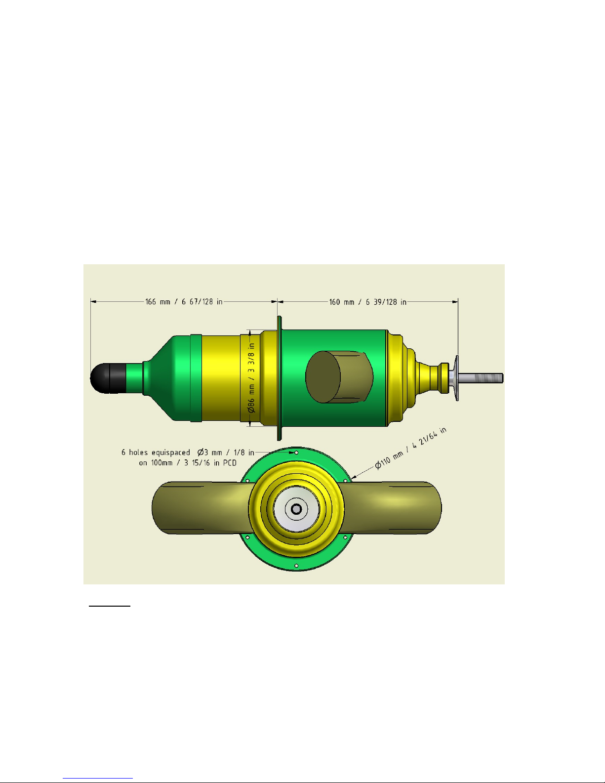
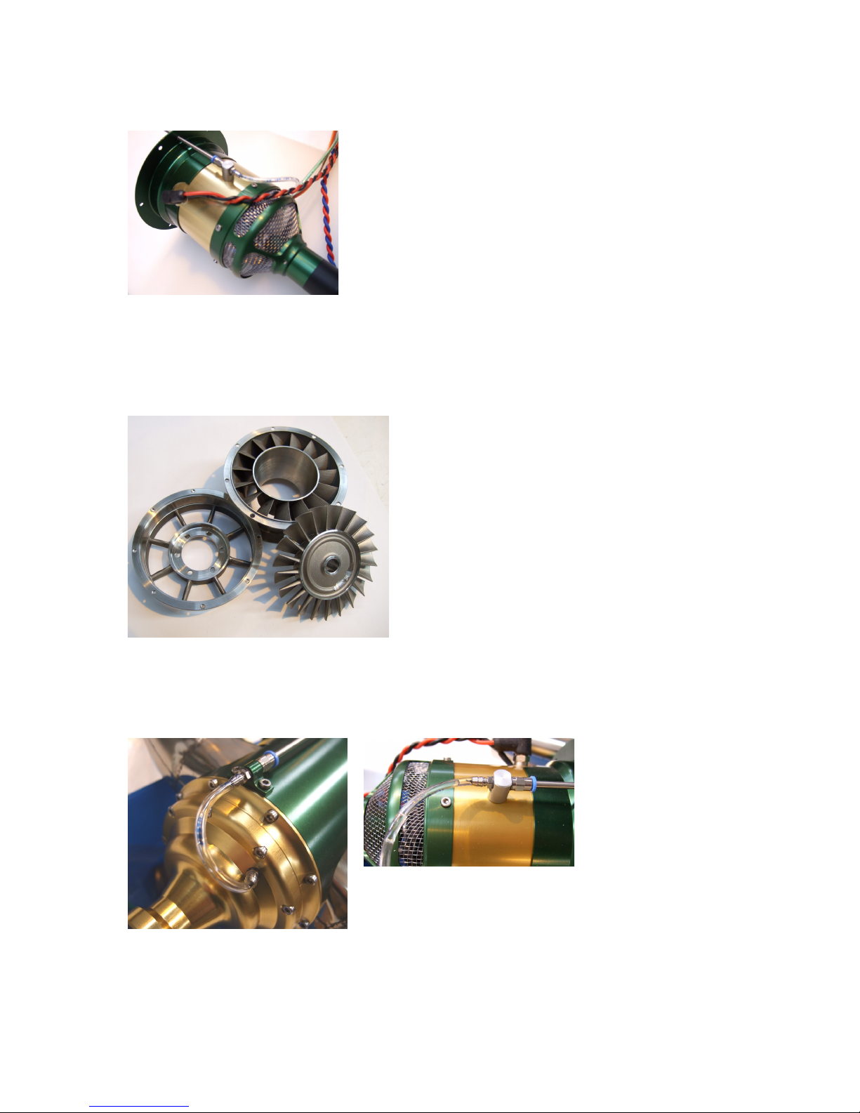
How is it mounted?
The unit is housed within a purpose made containment system which encloses the hot section
components in a three-section aluminium jacket enabling the installation to be limited to a simple
firewall mounting and six bolts and nuts. This firewall provides the essential air separation for gas
generator intake air and the warm air generated by the exhaust unit by placing a solid partition
between them. In normal running the casing will only reach about 100-130'C minimising the
chances of heat damage to the aircraft fuselage. No further stiffening is required or advised for
the unit, this approach enabling the conversion from I/C engine to turbo-prop power to be
accomplished with ease. The mounting supports the engine and gearbox at the approximate
centre of gravity and is built to withstand all normal loads such as might be subjected to the
equivalent I/C engine.
Aren't gas turbine more dangerous than I/C engines?
No. In the unfortunate event of a sudden arrival (or crash) the mounting helps to maintain
containment of all the hot section parts from heat sensitive parts of the airframe and accessories.
Turbine fuel has a high flashpoint which means at normal ambient temperatures it is extremely
difficult to ignite, unlike gasoline or glow fuel which is a low vapour temperature and ignites easily.
With no exposed high temperature components the risk of accidental combustion is greatly
reduced. As starting is undertaken with the operator and observers behind the propeller there is
no possiblility of a sudden power surge allowing the aircraft and propeller to run forward to the
operator such as can happen with I/C engines, with disastrous consequences for fingers and
limbs. The 2nd stage fully encloses the outlet of the gas turbine section affording a high degree of
protection against any component failure due to accidental damage or persistent operation
beyond the normal operational duty cycle.
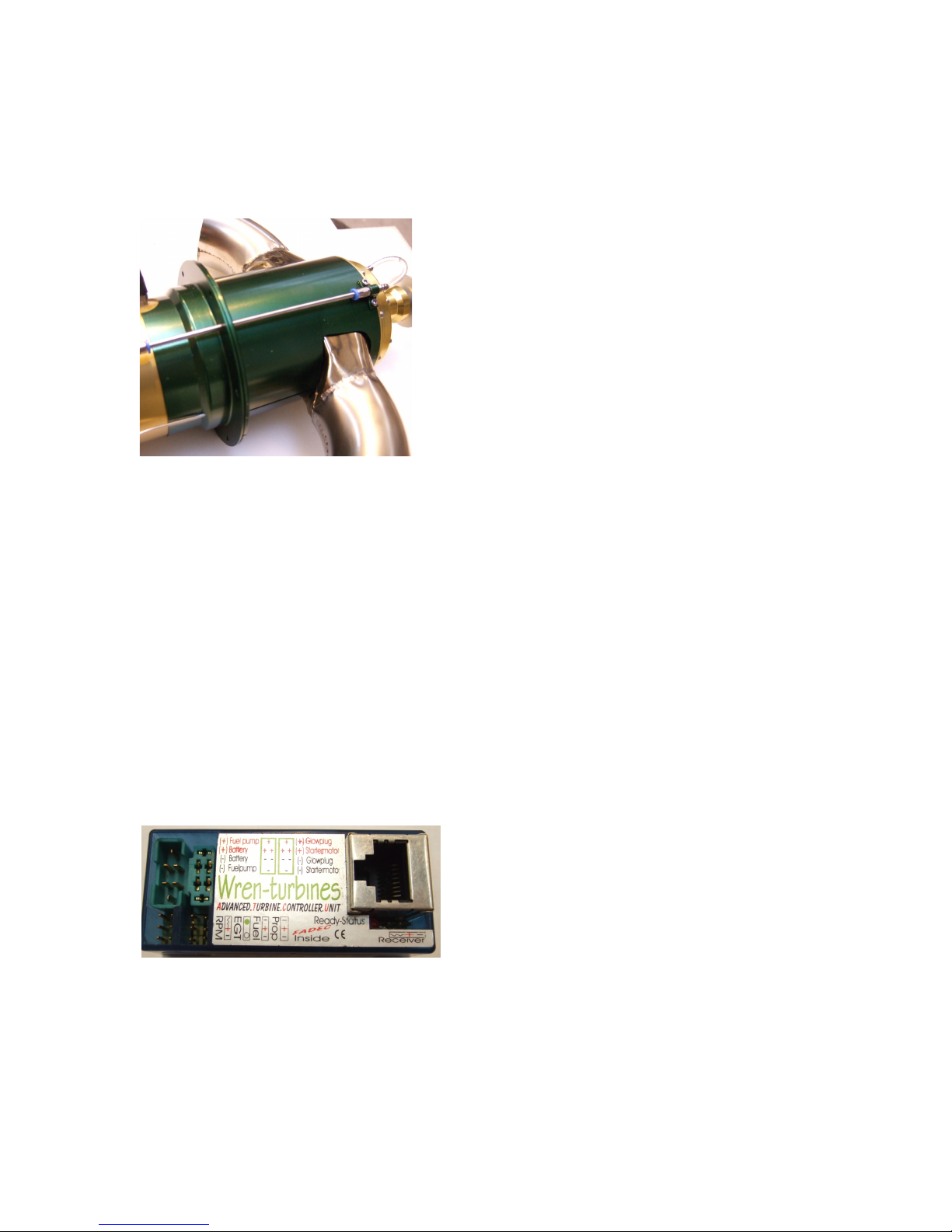
What's it like to operate?
The power unit itself is operated as a normal miniature gas turbine and possesses all the
standard features of automatic push-button starting and cooling, totally vibration free operation,
very quiet running and exceptional power to weight ratio. The throttle response is of the best in its
class - the small gas generator rotor is small and light allowing very quick spooling to be achieved
safely. Being a very small gas turbine it's fuel consumption has been described as "stingy" - a
typical 10minute flight being easily achieved with a single 1ltr fuel tank, depending on the flying
style. Those fliers used to a 3ltr fuel tank for equivelent flights should find this aspect of operation
a welcome relief.
How does it compare to I/C power?
The exceptional power to weight ratio which is close in performance levels to an 80cc gasoline
engine but weighing in at only 1.71kg (3-3/4 lbs) allows the operator a level of dial-in performance
previously enjoyed by only those operating high performance specialist engines with tuned pipes
etc, with all the attendant noise, extreme vibration and operational issues associated with such
equipement. Scale fliers will really enjoy the smooth and quiet response and operation coupled
with high power reserve to get out of those difficult situations that scale aircraft with fully
articulated surfaces, flaps and fine surface detail, can find themselves in. The high torque ability
of the engine allows it to cope well with a wide range of prop sizes and shapes which will enable
those scale three and four blade props to be a practical reality and further add scale effect.
Almost all aircraft will enjoy an installed power to weight ratio exceeding 1:1 - in many cases

Wren 44 TurboProp Users Manual. Copyright Wren Turbines Ltd February 2008 Page 8
exceeding 2:1! With a static thrust exceeding 16kg (35lb) the unit should be quite adequate in
power to enable an acceptable flight performance in a plane of 25kg (60lb) or more.
What about flying in noise sensitive areas?
Fliers with noise sensitive flying fields will enjoy the almost silent operation of the unit comparable
to electric flying. Such users are encouraged to make good use of the current crop of quiet
propellors and resist the temptation to zoom around the field like a pylon racer! Sports fliers can
make full use of the highly tractable response and enjoy quelling the myth that turbo-props cannot
prop-hang.
What about smoke?
The engine itself is a clean burning gas turbine that does not produce any smoke in normal
operation. However the gearbox bearings are lubricated with a very small amount of fuel which at
low rpms or throttling down can sometimes be seen as a small puff of smoke, but this is normal.
The minimal oil percentage used in the fuel helps to minimize pollution from unburnt fuel,
although operation of the gas turbine does produce an very distinguishable smell which for many
is the "raison detre" of this type of model flying.
What propellers do you recommend?
An important question. In all cases, we recommend only wooden props as in the even of a nose-
over in a taildragger aircraft, the prop will break and not damage the engine. Similarly, in the
event of an undercarriage failure where the u/c will not extend and a belly landing is required, a
prop strike is inevitable and a strong carbon prop will not bend enough to protect the engine and
can cause serious damage to the propshaft. Wooden props are available in sufficient styles and
shapes to cover most needs although users should satisfy themselves in the case of three or
more blade props, that the hub fixing is adequate enough for the power of this engine.

Wren 44 TurboProp Users Manual. Copyright Wren Turbines Ltd February 2008 Page 9
Detail description of the Wren 44 two-shaft drive system
Gas Generator
The gas generator used in the system is the well proven
Wren 44 GOLD engine which has the standard Wren FOD
guard fitted – this is no place for a tea strainer. A lubrication
port in the outer casing has been added and this connects
through a stainless tube to the gearbox. Other than the lube
outlet there are no other changes to the engine and the full
throughput has been utilised to generate shaft power.
This TurboProp engine has been fully run and tested
It is important to stress the unit has been fully tested with all the components supplied with it
before it left the factory at Wren Turbines Ltd. There should be no need to make adjustments
other than setting the radio to the ecu. Please refrain from jumping in and changing things just
because you or a friend have another Wren 44. The settings match the components used and
may not be the same as you are used to.
Hot Section
A specially designed and manufactured miniature
interstage and guide vane assembly, cast from high
temperature stainless steel is bolted to the engine.
A purpose made 66mm power turbine – not just
taken from a thrust engine, is cast in Inconel 713c
and is fitted and running on a fully hardened and
ground shaft in a pair of preloaded high speed
ceramic angular contact bearings. The shaft tunnel
they run in is made from low expansion stainless
steel.
These components define what is called the hot
section. Nothing has been left to chance.
Gearbox
The front of the turbine shaft is contoured with a hardened and ground gear profile and supplies
the shaft power into a specially design high speed planetary gearbox. This heavy duty assembly
utilising fully ballraced support shafts and the planet carrier has been ground and bored as an
assembly to retain great strength and accuracy.
The housings are
anodised to resist
corrosion and maintain
their lustre. The gears
are fully hardened and
are able to run with
long life using just a
small amount of engine
fuel bled off the gas generator fuel system. To keep the flow
to a low level the oil percentage is maintained at 5% to
ensure satisfactory lubrication.
The lubrication reaches the gearbox by a small pipe in the gearbox front wall and is fed from a
special fitting mounted on the engine. The gearbox is designed to retain much of the lubrication
and only release what is surplus via the power turbine bearing.

Wren 44 TurboProp Users Manual. Copyright Wren Turbines Ltd February 2008 Page 10
The Mounting
The gearbox housing incorporates a Wren Turbines’ innovation – a fully integral mounting
system. This specially designed housing answers two of the criticisms of turbo-props – that of
their generally awkward mounting arrangement for gearbox and engine, and the amount of heat
they generate within the airframe.
Our unique new system is machined from solid aircraft
grade aluminium and carefully anodised to retain its
corrosion resistant qualities and durability of finish. It
provides a secure and rigid connection between the
firewall and gearbox and provides full support to the gas
generator at its C of G. This eliminates the danger of
distorting the hot section between the engine and
gearbox when individually clamping engine and
gearbox to different sections of the airframe. The Wren
system also allows a very simple mounting for the
engine – just align the supplied template (at the back of
this manual), and cut out the shape, drill the six mount
holes and bolt onto a firewall like a 2-cycle engine. This
also allows for the simple offsetting of the thrust line by
simply building it into the firewall at the point of construction, as recommended or included for the
I/C installation.
The mounting has a further advantage – it envelopes the hot section and exhaust sections and
holds in the heat which would normally be released to the interior of the aircraft. Such heat
release can cause heat damage to paint finishes cowl materials, or make it difficult for the engine
to get an adequate supply of essential cool air for the engine to run on. We think the system is so
good that some day all turbo-props will look like this.
Ancillaries
ECU (Engine Control Unit)
Data display terminal
RPM pickup (mounted in engine)
Temperature Probe (mounted on engine)
Fuel pump
Propane valve and flow restrictor
Fuel valve
Ecu battery
Propane tank
ECU (Engine Control Unit)
The ECU and ancillaries are identical to the thrust engine
variant and use similar programmed settings. It is
important however, that users do not change settings
from those set without refering back to Wren Turbines.
The ECU is the well proven Digitech type supplied by
Gaspar Espiell and which the engine, fuel pump and ecu
battery plugs into. It controls the engine through its
starting, running and cooling down phases. A signal lead from your receiver connects to the ecu and
provides the throttle commands to the engine from the receiver throttle channel and next to it is the larger
socket for plugging in the Data terminal (see below). The ECU unit has a printed label which shows where all
the engine accessories are plugged in; “RPM” - rpm pickup (the servo-type lead coming out of the cowl of
the engine), “EGT” - temp’ probe, “Fuel” - fuel valve, “Prop” - propane valve. To orientate these servo-type
leads, the “-“ refers to the brown wire. There are various timers that are used to keep track of running hours
– see the detail section on setting the ecu.

Wren 44 TurboProp Users Manual. Copyright Wren Turbines Ltd February 2008 Page 11
Data Terminal
The ecu is accessed from the outside world by a port with a telephone style
socket connector and a hand-held unit called the Data Terminal.
This terminal is primarily a display for the engine but is also used to input
settings from buttons on its front panel. The terminal’s functions are
described in more detail later.
RPM Pickup
Mounted on the front of the engine, under the FOD screen is a hall-type
magnetic rpm sensor. It picks up a signal from a small magnet fitted into
the compressor nut one the end of the shaft of the engine. The signal
terminates in a servo-type plug which plugs into the rpm input on the
ECU.
The pickup is sensitive to stray magnetic and electrical noise so be careful
about routing cables close to it. The starter and glow plug cables are
tightly twisted to reduce their stray signal for this reason – do not untwist
them.
Temperature probe. The temperature probe is a standard
miniature industrial thermocouple which is positioned in the
interstage casting via the engine bulkead and senses the
exhaust temperature of the engine and feeds this
information back to the ECU.
Temperature information is used to detect sufficient pre-heating at the engine start phase and correct
operation during normal running. On shutdown, the temp’ probe indicates to the ECU when the engine has
cooled sufficiently during the cool-down phase. It is secured on the front of the engine and connects to the
ECU via a small servo-type plug with a special green cable. It is attached to the engine and should not be
moved from this position.
Fuel Pump. The fuel pump is one of two special
gear type pumps especially made for the Wren 44
and turbo-prop. They have very small gears to allow
a wide range of control for the engine and must not
be substituted for anything else. Almost all other
turbine fuel pumps are much too large and are
therefore not suitable for this application and result in
loss of control on this engine. Be very careful whenever disconnecting or connecting it
to ensure there are no small slices of pipe left at the inlet or outlet.
When people say that “cleanliness is next to godliness” they are referring to small turbine fuel pumps. Treat
this component with total reverence and keep it spotless. Always carefully blank off the pipes with clean
blanks, when moving it about. The smallest particle can spoil the operation of this pump so only allow clean
fully filtered fuel into it. Connect to a fuel tank by a single direct pipe with no connectors, fuelling valves,
stoppers etc between it and the fuel pickup. The pickup should be a quality felt type clunk or propietry pickup
with fine filtering qualities.
ALWAYS carefully filter the fuel going into the tank, don’t rely on the pickup to stop particles getting in. If a
tank gets badly contaminated then discard it – this engine is far too costly to risk a dirty tank. Be careful also
to ensure any tank vents cannot suck grit into the tank. A filter on the air vent is not going too far to keep the
fuel pump in tip-top condition.
Propane Valve
This valve is a specially made brass body valve used to switch the propane gas on and off
during the start phase. It has an “in” and “out” (marked by an arrow). The valve is powered
by the propane outlet on the ECU and care should be taken to ensure it is plugged into the
correct ECU socket. The valve coil is rated at 5v and may be tested with a 5v supply where
a solid click can be heard. If it malfunctions the valve is not user serviceable and must be
replaced. It is identical to the fuel valve in construction. Note – the “F” on the side of the
valve base indicates the direction of “Flow” and not “Fuel”.

Wren 44 TurboProp Users Manual. Copyright Wren Turbines Ltd February 2008 Page 12
Flow Restrictor
The “out” side of the propane valve has a short length of green tube attached by a quick
release connector to a small adjustable “Festo”- type flow valve. This valve controls the
volume of propane flowing to the engine for starting. It has been preset to the setting
required for starting as part of the engine test so should be approximately in the right place
already. There is a locknut just below the small blue control knob to help prevent it coming
undone and should be loosened before making adjustments. Do not adjust the valve until
you have tested it on an engine start and found you need to change the setting. It has a
soft seat and fine thread so it is not easy to tell if it it fully closed or not.
To confirm operation, unplug the outlet to the engine and connect a short length of 3mm tube to the valve
outlet. Fill your propane tank or connect up your usual supply, go for a start and after a click there should be
a hiss of flow coming out of the valve. If not open the valve gradually until it does. Note the ecu will only
allow about five attempts at a start on a single attempt before it shows “TimeOut”. If this happens simply put
the trim to off, then raise again to on and try again.
Fuel Valve
This is the same construction as the Propane valve with the same
direction arrow. Test by simply blowing through while plugging it into a
spare servo outlet on your receiver. There should be a click on powering.
Again if it fails there is little to be done but replace it. The quick release
connectors can be removed for re-use first though
.
ECU Battery
The ECU battery supplied is a 2-cell 7.4v Lithium Polymer (LiPo). The capacity of
this should be enough for at least three good flights but initially we recommend you
charge after each flight to keep tabs on how much is being taken out by the flight.
LiPo’s must be charged with a charger especially made for this type of cell and we
recommend those equipped with a balancer, or which charge through a balancer.
The battery has a balancing lead and it is best if you charge through this.
Warning. It is very important you disconnect the battery from the ecu while charging
or permanenet damage to the ecu can result. Such damage is checkable and ecu’s so damaged will not be
replaced under warranty. It is good practice anyway to remove the battery from the plane and charge in a
safe area.
Battery care - after flying. It is most important that the battery is disconnected at the end of your flying
session. The ECU uses only a few milliamps when shut off but this can drain a LiPo down to nothing in a
couple of weeks. In this case the battery is deep discharged and permanently damaged – ie scrap. A LiPo
so discharged will not be covered by the warranty.
Propane Tank
This small tank is supplied for customers who wish to have an on-board propane system.
It is intended for mounting upright in the plane and to hold enough for four or five starts. It
is intended to be only filled to about 1/3
rd
to ½ full maximum. The connector on top
enables the feed supply from the outside to enter the tank and the outlet supply to exit the
tank to the propane valve separately. The advantage of this system is if it is a very cold
day you can simply leave your external propane supply plugged into the tank but not
supplying liquid, and make your start as normal, making use of the larger capacity of the
external supply.
It is good practice to vent the propane tank at the end of the flying session to ensure no
propane is left in the system that if seeped out could present a fire hazard.

Wren 44 TurboProp Users Manual. Copyright Wren Turbines Ltd February 2008 Page 13
Off-Board Propane
Many fliers prefer to have off-board propane supply and in this case, simply pipe the quick release fitting
directly to the propane valve. The quick release connector and pipework is supplied to enable either
arrangement to be achieved.
Canister valve
A canister valve is also supplied to screw onto your propane canister.
Traditionally this has only fitted canisters available in Europe but these are
now becoming common in the USA. This simple valve operates by
pressing the small sealing ball off its seat in the neck of the canister.
Control is attained by how far the ball is moved. The control works as a
normal tap, ie to turn on the propane turn the screw cap anticlockwise in
the “+” direction, to turn off rotate clockwise in the “-“ direction. It is not
necessary or desirable to move the cap more than about three or four
turns as the cap can be undone totally until it falls out – potentially
allowing a propane escape.
Warning
Whatever system you adopt it is very important not to allow liquid propane to reach the engine. This can
cause flaming and aggressive starting and can damage the engine.
Secondly
It is most important to remember that propane is highly flammable at all normal temperatures. Please be
very careful during filling or purging to keep everything away from sources of ignition.
Thirdly
Also remember that at high ambient temperatures pure propane can attain very high pressures that can
cause pipes to blow off their connectors. If it is deemed there is any possibility of this happening or if you
experience this, then switch to external plug-in propane which reduces significantly the possibility of large
propane release inside the aircraft.
SAFETY NOTES
We make no apologies for positioning these notes early in the manual. Please read the following
for your own safety and those around you - thank-you.
This engine is not a toy and can cause bodily harm to you or others if misused.
It is your responsibility as owner, to ensure safe, careful and considerate operation of your engine
at all times, and in accordance with the manufacturers instructions.
If you sell or give away this engine, please pass these instructions to the new owner.
This engine must only be run firmly attached to a secure and sturdy engine test stand or model
installation. The thrust is very considerable for such a small size and mountings must be sufficient
to withstand such forces. Use appropriate screws and proper captive nuts. The engine must
never be run held in the hand or clamped in a vice.
This engine is an internal combustion gas turbine engine which generates large quantities of heat
– ensure the mountings and installation are appropriate for operation at these elevated
temperatures.
During operation and for a time afterwards there are parts of the engine which are hot enough to
cause serious burns – do not touch any part of the engine until it has cooled to room temperature.
Always operate your engine in open air away from confined spaces as the engine exhaust
contains gases which can cause asphyxiation and nuisance from smells.

Wren 44 TurboProp Users Manual. Copyright Wren Turbines Ltd February 2008 Page 14
The exhaust gases are very hot (over 400’C) on leaving the engine and can cause burns to skin
or damage to objects close to it – keep exhausts clear of anything which is affected by such heat.
This engine must not be used near flammable gases, liquid or materials.
Always keep a CO
2
or similar fire extinguisher close by when operating this engine.
Turbine fuel is poisonous to living beings. Keep it away from the mouth and eyes and from
contact with skin. Always store it in a marked container out of reach to children.
Turbine fuel has a relatively high flash-point but in certain circumstances can be highly
flammable. Keep it away from heat and sources of combustion.
The starting gas (propane) is highly flammable and must be used with extreme care. Maintain
canister and fittings in good leak-proof condition. Protect from sunlight and prevent exposure to
temperatures exceeding 50’C. Keep out of reach of children. Discard used canisters in a safe
place and do not puncture or incinerate, even when empty. Avoid deliberate inhalation.
Ensure gaseous propane only is supplied to the engine, liquid gas must not be allowed to pass
into the system. Gas supply must be disconnected until ready for immediate use. Gas is heavier
than air and can fill a model if allowed to leak unchecked, and become a potential explosion
hazard.
Turbine oils can be hazardous to health and must not be allowed to come into contact with skin,
mouth, eyes or through ingestion, accidental or otherwise. Take care when decanting and ensure
any spillage is wiped away immediately and clean any affected area with warm soapy water..
Wash hands and any affected part immediately after any contact.
Turbine oil can discolour or affect certain paint finishes . Take precautions to prevent spillage.
Do not discard or allow any spillage to run into drains.
If removing the glow-plug to test it, keep fingers or bare skin away from possible burn from the
glowing element – use a metal tool or appropriate insulation.
As operator, it is your responsibility to ensure any spectators (especially small children) or helpers
are kept well away from the engine whilst it is operating. The safest position to operate the engine
is in the area behind the propeller. The area sideways on to the engine is potentially the most
dangerous area due to the rotating propeller. You and people around you must keep well clear of
this to a safe distance. In certain light a turning propeller can become invisible – add some colour
to the propeller tips if you notice this with yours. If operating from a pit area take special care as
safety distances are often difficult to maintain and passers by can appear without warning.
Keep all helpers close by and brief them fully on their duties before starting the engine. One
helper should carry out the role of fireman. Ensure they are aware of what to do in event of
emergency and where to position the extinguisher if required.
Never attempt to alter the starting characteristics of the engine by spraying ignition agents into
the intake, as might be used for gasoline and diesel engines. A dangerous fire and flashback may
result.
Please note, the exhaust of a gas turbine has a pleasing smell to enthusiasts of gas turbines but
others may find it offensive. Please have consideration for others when running your engine in
their proximity.

Wren 44 TurboProp Users Manual. Copyright Wren Turbines Ltd February 2008 Page 15
The warranty
Wren Turbines warranties this Wren44 TurboProp engine and associated equipment, free of mechanical
defects in workmanship or materials for two years after purchase date.
Engine Control Unit (ECU).
The ECU has a one year warranty which covers repair or replacement of the main unit and the display.
Improper use such as polarity reversal, short circuit, ingress of foreign matter or crash damage is excluded.
Warranty Conditions:
1 The engine may not be dismantled except the removal of the front (green) cover, to access
the service connections and speed sensor.
2 The fuel pump, ecu and rpm pickup may not be dismantled or manufacturers seal/covering
broken by way of investigation. If either unit is suspected as defective it should be
returned intact to Wren Turbines Ltd who will check the serviceability of the item and
replace if found defective.
3 The engine MUST be started and operated exactly as instructed. This includes (i) correct
mounting of the engine with correct inlet and exhaust ventilation (ii) use of the correct
battery packs (iii) use of the supplied fuel pump (iv) use and correct operation of the
supplied ECU, (v) use of supplied wiring harness.
4 Only the recommended fuel is used.
5 Excludes parts damaged by excessive heat due to incorrect operation (starting, running,
cooling etc).
6 Excludes parts damaged by ingestion of foreign objects (ie wires, model materials and
fittings, water, sand or grit).
7 Excludes engine repairs where blockages in the fuel system have occurred due to use with
unfiltered, or contaminated fuel.
8 Excludes damage to the unit in event of nose-over or damage inflicted through prop-strike.
9 Crash damage to the engine and its ancillaries is not covered by the warranty.
10 Warranty is not transferable.
Notes for the inquisitive.
Please do not attempt to disassemble this engine. You will breach your warranty agreement and you will find
it is a precision assembly which you will be unlikely to re-assemble without considerable difficulty and
specialist equipment. Simply slackening the spinner nut of the rengine otor may lose the delicate balance
condition without which the engine may not run without damage to its rotating assembly.
You are permitted to access the fuel and gas connections under the green cover in event of repair or
replacement of the fuel or gas pipes. Access may also be gained to the magnetic rpm pickup if repair or
replacement is required. Access to the gearbox should never be required. It does not require cleaning out or
additional lubrication so should be left alone.
You may not dismantle the engine further. Any further investigation must only be undertaken by Wren
Turbines Ltd.
Repair.
Damage or defective operation covered under the warranty terms will be repaired and tested at no cost to
the original owner (other than post and packing). Repairs not covered under the terms of the warranty will be
carried out by Wren Turbines Ltd, or their appointed agents, after agreement of costs.
Before returning the engine or ancillary equipment for service or repair, please contact Wren Turbines Ltd or
Wren Service Agent to agree action and costs. When returning an engine please be sure to seal both gas
and fuel pipes and pack the pump and engine unit in clean polythene bags to prevent entry of dirt.

Wren 44 TurboProp Users Manual. Copyright Wren Turbines Ltd February 2008 Page 16
Performance
We have tested the turboprop unit in a variety of situations and loads. The main indicator of the
performance of the unit from the users point of view, is the rpm that can be achieved with a given
propeller load. Larger propellers and/or more blades produce higher torque figures but not always
the highest thrust figures.
We have listed the outputs for a range of propellers and the thrust produced for each combination
together with the calculated torque and shaft power figures. From these it should be possible for
the reader to gauge the ideal propeller combination for their aircraft.
The figures are reproduced in order of highest thrust first and are with gas generator at maximum
speed - 195,000rpm.
Propeller Size RPM Static Thrust Torque KW HP
2-Bladed:
MENZ-S 610 x 200 (24” x 8”) 7110 167N 6.82Nm 5.08 6.81
MENZ-S 610 x 305 (24” x 12”) 5900 160N 7.06Nm 4.36 5.84
APC-N 430 x 305 (17” x 12”) 8900 95N 4.49Nm 4.18 5.60
3-Bladed:
Mejzlik 560 x 305 (22” x 12”) 6300 150N 8.52Nm 5.62 7.53
Mejzlik 510 x 305 (20” x 12”) 7020 135N 7.22Nm 5.31 7.12
MENZ-S 460 x 305 (18” x 12”) 7540 128N 5.47Nm 4.32 5.79
Note the high rpms achieved with the smaller propellers. It is most important that propellers
smaller than listed are not used or if they are the maximum rpm should be reduced on the engine,
to prevent the possibility of overstressing (the propeller). In all cases, follow the propeller
manufacturers recommendations for preparation and use.
NOTE
The maximum speed of the unit with any propeller should not exceed 9,000rpm on the ground.

Wren 44 TurboProp Users Manual. Copyright Wren Turbines Ltd February 2008 Page 17
Propeller Selection and Balancing
Some examples may help to answer questions about choice of propeller:
1) Slow flying “glider-tug” 2.5m span. Ideal propeller is a large diameter around 560-610
(22”-24”) and shallow pitch around 200 – 250 (8”-10”). If there is a problem with
ground clearance with the larger diameter, then a 3-bladed one can be selected. In
this case a diameter of around 50mm (2”) smaller in diameter - 510 (20”) would be
suitable, with a 250 or 200 (10” or 8”) pitch.
2) Fast flying sports type “Extra” or similar 2.20-2.5m span. Ideal propeller is 560 x 305
(22” x 12”) 2-blade or 510 x 305 (20” x 12”) 3-bladed. The larger pitch and smaller
rpm allows a higher propeller rpm and corresponding high forward airspeed.
3) Reasonably fast scale type “Tucano” or similar, 2-2.5m span scale type. Ideal size is
560 x 305 (22” x 12”) 3-bladed. The larger diameter and pitch enables plenty of thrust
for good forward speed with a quiet operation and scale appearance.
It is worth noting that the thrust measures are static figures, the dynamic thrust (when the aircraft
is in flight) will reduce as aircraft airspeed increases and is a function of all propeller driven
aircraft. However, it is worth reminding that the thrust on a turbo-prop falls off more gradually than
an I/C engine due to the fact that as the propeller load reduces due to forward speed
(“unloading”) it’s rpm rises to balance the torque supplied. This feature enables turbo-prop
powered aircraft to achieve a higher forward speed than the static rpm suggests, or the same
speed achieved for a reduced throttle setting.
Ultimate forward speed, it should be reminded is mainly a function of forward thrust against
airframe drag. A slippery airframe will result in far greater performance on even modest power
levels, whereas a large draggy airframe may fly slowly on even exceptional power.
Propeller Balancing
It is imperative that propellers used on the turbo-prop are balanced to a fine degree as the engine
is produced utilising a high standard of balance on assembly. A standard propeller, new and just
out of the box is very likely to be significantly out of balance and using it in this condition can
cause damage to the engine through excessive and rapid wear on bearing journals and potential
fatigue failures of the fuel system in the engine. Such imbalance can be easily seen when an
engine is running by the tail fin or tail surfaces trembling.
Balancing is equally important if you plan to install a spinner,
particularly if it is one that has an aluminium backplate. Such
spinners can have a similar severe effect on the smoothness of the
unit and must receive similar care to the propeller.
Simple and highly effective propeller balancing units based on a pair
of magnets have been available commercially for many years (see
the “Top Flight” one at left), or alternatively those with facilities can
produce their own. Imbalance correction is normally a combination
of scraping the heavy blade evenly towards the end of the blade –
never at the root as this can weaken it. Alternatively, light sprays of
clear fuel proofer on the light blade will achieve the same result.
Important - No attempt should be made to add material,
lead shot or coloured sticky tape to the light blade as this is sure to fly off later and if you are
lucky it might not to hurt someone, but the resulting out-of-balance running could cause major
engine damage. If this happened in the air you would not know until it was too late. The warranty
will not cover you for such damage.

Wren 44 TurboProp Users Manual. Copyright Wren Turbines Ltd February 2008 Page 18
Fuel Consumption and Flight Time Endurance
Fuel Consumption
Fuel consumption means the quantity of fuel required to achieve the specific power level
indicated. For fliers, it is not such a useful figure as it is a single setting quantity and doesn’t
represent actual flying. The full power figure is useful as an indicator of the worst case maximum
consumption figure and the likely minimum flight time achievable. Endurance basically means
how long a plane can fly under power for a given quantity of fuel, including take-off and landings –
there must be at least one of each of these for every flight!
The fuel consumption of the turbo-prop unit is proportional to the power used and for most fliers
this will vary considerably depending on the type of aircraft and duty undertaken. A slow flying
glider tug might use full power for one minute and then reduce to quarter power to circle for
several minutes and land. A fast sports type aircraft might use full power extensively during its
flight including prop hanging and full power ascents. A scale type model might use full power for
just a few seconds for take-off and never use full power again in the flight.
So fuel consumption figures must be used sensibly with an eye on how the engine is operated.
Fuel tank capacity
The duty cycle anticipated of the aircraft will impact the choice of fuel tank capacity. There is little
point carrying around 3ltrs of fuel if the flying requires only 0.4 ltrs per flight. Equally there is no
point having a 0.5ltr tank for a fast aerobatic aircraft that is required to perform an eight minute
show slot (it won’t!).
In general we recommend a compromise tank size for most aircraft of 1.5ltrs (50oz) which should
allow plenty of flight time (8mins+) and assures a reliable supply of fuel and a decent reserve to
keep the system filled.
It is not good practice to choose too small a tank as you run a greater risk running the tank dry
which will allow air to enter the fuel system. This can be difficult to remove afterwards and can
make the system unreliable if air bubbles remain. If you plan a lot of high power manouvers
and/extra long flights then a 2ltr tank may be a better option. It is sensible to allow for about 25%
extra capacity from your requirement to ensure consistent fuel supply.
Fuel Consumption in ml/min to Engine
RPM
0.0
40.0
80.0
120.0
160.0
55
100
130
160
180
195
Engine RPM x 1000
Fuel consumption in
ml/min
Fuel Consumption Fl/oz to Engine RPM
0.0
1.0
2.0
3.0
4.0
5.0
6.0
55
100
130
160
180
195
Engine RPM x 1000
Consumption in fl/oz per min

Wren 44 TurboProp Users Manual. Copyright Wren Turbines Ltd February 2008 Page 19
Hopper Tanks and UAT’s
Hopper tanks and UAT’s (originally the Ultimate Air Trap from BVM Models) are a popular choice
and can help with the consistency of fuel supply – especially on aerobatic models. The standard
hopper tank is simply a small capacity fuel tank which is fully sealed and has a single fuel-in pipe
and a fuel outlet positioned centrally so it can pull fuel from any attitude the plane finds itself in.
The UAT is similar except it has a membrane type pickup on the fuel-outlet which acts as a
sponge and allows fuel to pass but without allowing air into the system.
Fit the UAT or hopper tank between the fuel tank and fuel pump – take great care to ensure a
totally fuel tight pipe run from tank to UAT/hopper and then onto the fuel pump. Purge all air
bubbles from the UAT or hopper before use. Monitor the remaining fuel level in the UAT/hopper
as this is a good indication of of air getting into the system. If this level drops noticeably during a
flight and there is still fuel remaining in the tank, then suspect an air leak, find and cure it before it
causes a stoppage.
UAT’s are helpful, but the guide still applies – keep the tank capacity well above the flight time
requirement so the tank clunk is not chasing the last dregs of fuel around at the bottom of the
tank.
Flight Time Endurance
How long a plane can fly on a given quantity of fuel is only of academic interest to most but it
does give an idea where in the flight envelope is the most economical for those with an eye on
the longest flight times!
Looking at the graph above, a steady 100,000rpm on the engine equates to about 25N (5-1/2lbs)
thrust from the propeller, which is enough to keep a plane of 10-15kg (22-33lb) aloft at
reasonable altitude. In this case you could expect over half an hours flying on the recommended
fuel tank.
Note that for most aircraft, though it is perfectly feasible to anticipate a flight of over half an hour
of gentle flying, this would not only be a true test of piloting but also of the on-board ECU battery
(LiPo) which may be marginal if not fully charged before take-off. If you plan to attempt such
marathon flights we recommend a larger capacity LiPo for the ECU battery, possibly also a larger
receiver battery too (also a well charged transmitter), so there are no embarassing “quiet”
moments when the engine slows and dies and you have to land with fuel remaining but no
engine.
You can see where the engines reputation as being “stingy” with fuel comes from.
Flight Duration to Engine RPM for 1.5ltr
Tank
0.0
20.0
40.0
60.0
80.0
55
100
130
160
180
195
Engine RPM x 1000
Flying time in min
Flight Duration to Engine RPM for
50oz Tank
0.0
20.0
40.0
60.0
80.0
55
100
130
160
180
195
Engine RPM x 1000
Flying time in min

Wren 44 TurboProp Users Manual. Copyright Wren Turbines Ltd February 2008 Page 20
Installation
DO’s:
Ensure adequate supply of cold air to the engine intake behind the firewall. This must be an
independent supply and isolated from the area in front of the firewall which can get warm in
operation. It is good practice to fit a fine wire mesh at the entrance of this area to prevent buildup
of grass etc from clogging the engine intake. An ideal material for this is the fine high quality
stainless mesh available from Wren Turbines at modest cost.
Ensure adequate ventilation of the stagnant area in front of the firewall to prevent build-up of heat
around the exhaust sections from distorting the fuselage or cowling or affecting the paint finish of
same.
Ensure the area of the firewall is properly sealed using a sealer approved for use with turbine
fuels and oils.
Engine should be mounted using the six bolt radial-mounting. No other means of mounting the
engine is allowed.
Ensure the engine is firmly secured to the firewall using six M3 bolts, and captive nuts to prevent
pulling through.
Any up/down or side thrust should ideally be added to the firewall and not simply a couple of
washers under the engine mounting which can cause distortion of the mount and potential
alignment issues within the engine.
Ensure at least 6mm (1/4”) of clearance around the exhaust from any part of the cowl. The
exhausts get hot in use and may distort or discolour the finish if clearance is too small.
The glow plug and lubrication feed pipe must be positioned upwards – see the cutout template at
back of manual. This is to ensure correct operation of the engine internal lubrication system
during start-up. Inverted flight manoeuvres do not affect the lube system during normal running.
The fuel pump should be mounted at least 100mm away from the intake of the engine. The pump
can emit electrical pulses that cause the speed sensor to transmit incorrect rpm information to the
ECU.
The fuel pump should be mounted with the spindle in the vertical position with the motor
uppermost and the black cap downwards. In the event of any fuel seeping from the pump this will
not pass through the electric motor. Note the pump is supplied fitted with built in suppression to
reduce radio frequency noise.
The centre of the fuel tank should be mounted laterally as near to the centre of gravity (CofG) of
the model as possible. This will minimise the CofG shift as the fuel is used during flight.
If breaking a quick release “Festo” connection, always trim the last 6mm (1/4”) from the end of the
tube to expose a fresh area for the connector to seal onto. To release a “Festo” type connection,
push the blue ring inwards with one hand and gently pull the tube out with the other hand, whilst
holding the collar in its retracted position.
The air ducting to the inlet of the engine must have a minimum area of 2500sq mm, (4sq” )
equivalent to at least 50mm (2”) square.
If an extension to the exhaust ducting is required, it should be approved by Wren Turbines Ltd.
Table of contents
Other Wren Turbines Engine manuals