Wurlitzer 0048130 User manual

1
XII/06 GR-rs
TI - MA 138a
(0062386)
SERVICE INFORMATION
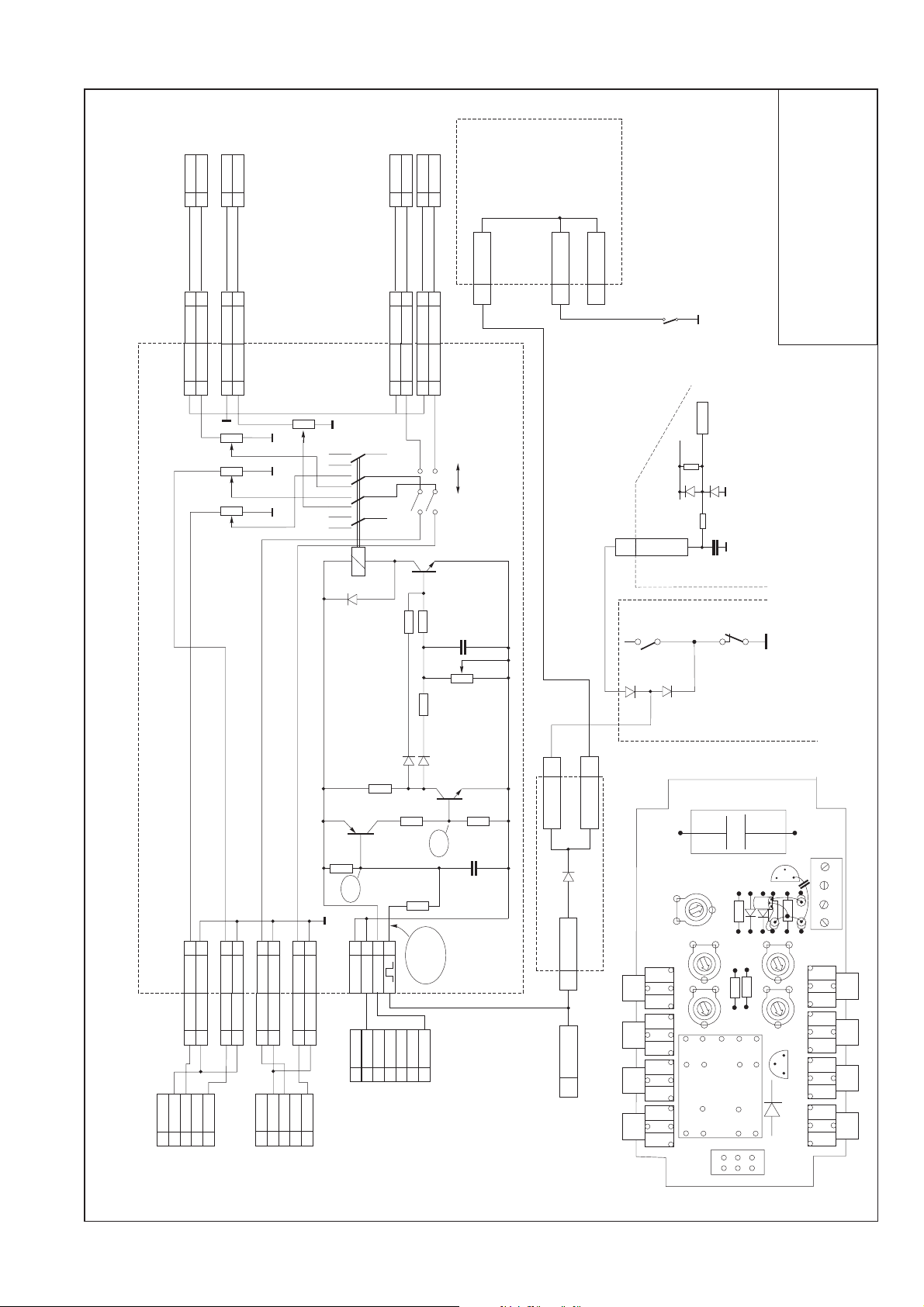
BGM Connector für Verstärker K99
und F91 (Art.-Nr. 0048130)
Für alle CD-Musikautomaten mit Verstärker K99 und F91
(aber nicht für Verstärker I84!).
Ersatzteilnummern
BGM-Adapter Kit kompl.
mit 2 Kabel 0048130
BGM-Adapter einzeln
0048133
Anschlusskabel 2 Cinch/
2 Cinch-Buchse
0037248
Kabel P7-Mikro.Anschl.
0035585
Kabel P9-P9 F91-BGM
0048131
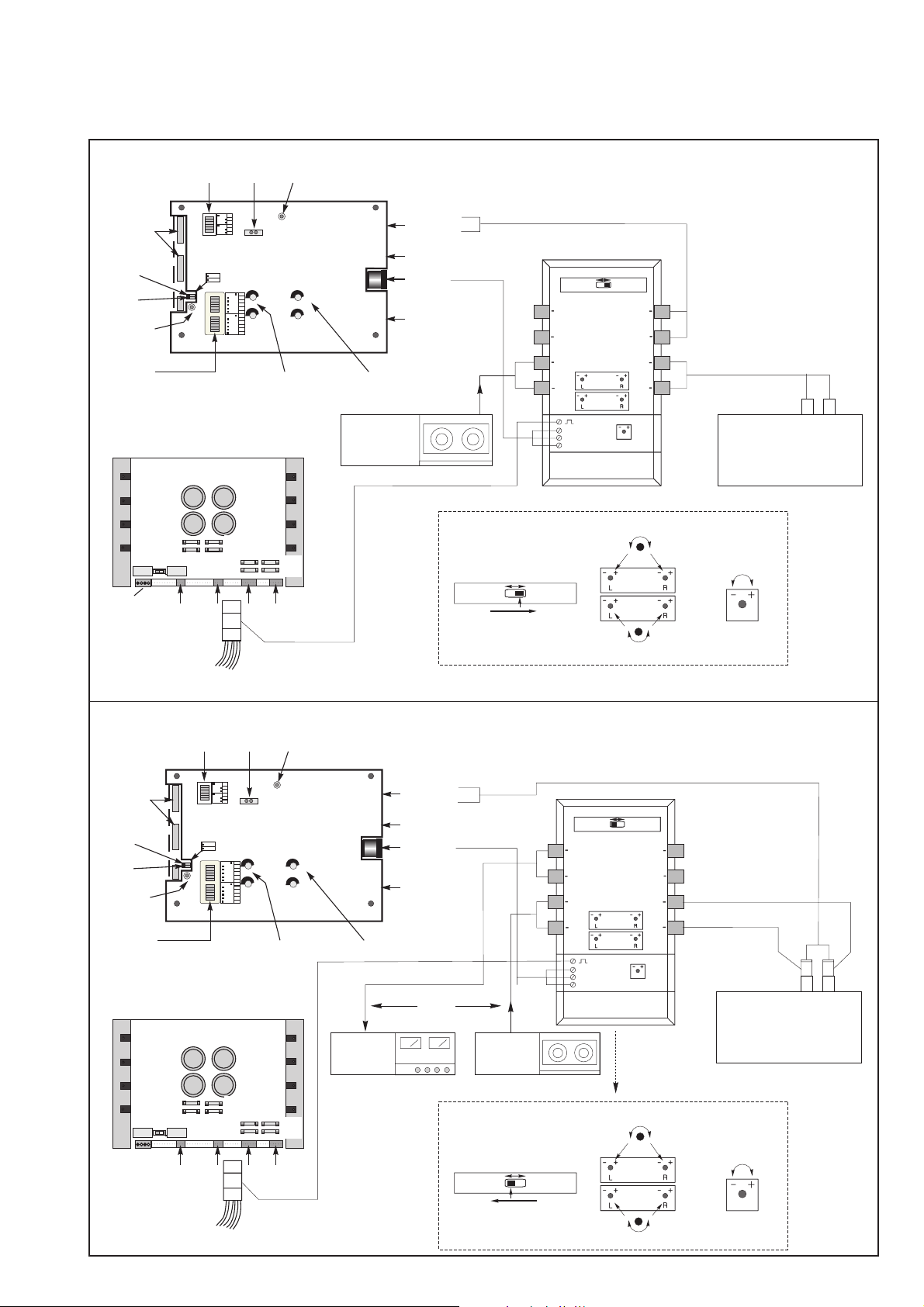
Der BGM-Connector erlaubt zwei Anschlussmöglichkeiten:
Version 1
Der Ton einer fremden Signalquelle (300 mV - 1 V), z.B.
Kassettenrecorder oder Radio, wird mit reduzierter Laut-
stärke über die Lautsprecher der Musikbox im Ruhebetrieb
wiedergegeben. Der BGM-Ton wird abgeschaltet, sobald
eine Wahl getätigt wird und erscheint wieder (Verzöge-
rungszeit ist einstellbar), nachdem alle gewählten Titel
abgespielt sind.
Elektrische Verbindungen (siehe Seiten 3 und 4,
Versionen 1)
Einstellung:
• Schiebeschalter in Richtung F91 Amplif.
• Potentiometer „CD Player“ auf max.
• Potentiometer „Ext. Tape“ einstellen auf gewünschte
Lautstärke für Backgroundmusik-Wiedergabe
• Potentiometer „Time“ einstellen von 10 - 50 sec.
Verzögerungszeit.
• Am Verstärker K99 den oberen DIP Schalter der Zweier-
gruppe „Mute“ auf OFF schalten (s. Seite 3).
Die Stummschaltung wird dadurch aufgehoben.
• P9’ Adapterstecker auf 1P09 am Verstärker zwischen-
stecken.
Music BGM Connector for amplifier K99
and F91 (part no. 0048130)
For all CD jukeboxes with amplifier K99 and F91 (but not for
amplifier I84!)
Spare part numbers
BGM adapter kit compl.
with 2 cables 0048130
BGM adapter only
0048133
Cable 2x Cinch plugs/
2 plugs sockets
0037248
Cable P7-Mikro.Anschl.
0035585
Cable P9-P9 F91-BGM
0048131
BGM mode allows two modes:
Mode 1
Distribution of sound from a background music device
(stereo cassette player or radio) by means of the jukebox
amplifier in stand by. If a selection is made, BGM is
interrupted and reappears after playing all tracks with an
adjustable delay of 10 - 50 sec.
Wiring (refer to pages 3 and 4, versions 1)
Adjustment:
• Set slide switch in direction F91 Amplif.
• Trim potentiometer “CD Player” on max.
• Trim potentiometer “Ext. Tape” adjustable to the volume of
BGM music in the jukebox
• Trim potentiometer “Time” adjustable between 10 - 50 sec.
• K99 amplifier: set the top DIP switch “mute” of the 2
switches block to OFF to disable mute in stand-by (ref. to
page 3).
• Insert P9’ sub plug between P9 plug and socket on the
power amp board.
• F91 amplifier: Cut off one side of resistor R 506 on the
power amp board to put out of action the mute circuit in
stand-by.
Extern.
Amplif.
F91
Amplif.
Ext.
Ampl
Ext.
Tape
Ext.
Tape
L
R
R
R
R
L
L
L
CD
Player
CD
Player
F91 Amp.
Aux.
0048133
F91
Ampl.
Micro
Music/BGM
Connector
+7,5V
-7,5V Time
Deutsche Wurlitzer GmbH
Wurlitzerstraße 6
D-32609 Hüllhorst
Tel. +49(0)5744 - 941-0
Fax +49(0)5744 - 941 220
www.deutsche-wurlitzer.de
R

2
• Beim Verstärker F91 auf der Verstärkerplatine (siehe
Seite 4) den Widerstand R506 einseitig durchkneifen.
Die Stummschaltung wird dadurch aufgehoben.
• Adapterstecker P9’ auf Verstärkerplatine P9 zwischen-
stecken.
Version 2
Sobald die Musikbox spielt, wird das Musikstück gleichzei-
tig auf eine vorhandene Musik- oder Verstärkeranlage
wiedergegeben. Die Hintergrundmusik wird in der Zeit
abgeschaltet.
Elektrische Verbindungen (siehe Seiten 3 und 4, Versionen
2)
Einstellung:
• Schiebeschalter auf Extern. Amplifier
• Potentiometer „CD Player“ => Pegel der Wiedergabe-
lautstärke von der Musikbox zur Hintergrundmusikanlage
einstellen
• Potentiometer „Ext. Tape“ => Pegeleinstellung der
Wiedergabelautstärke von einem Radio oder Kassetten-
recorder zum Verstärker der Hintergrundmusikanlage.
• Potentiometer „Time“ einstellen von 10 - 50 sec.
Verzögerungszeit
• Am Verstärker K99 den oberen DIP Schalter der Zweier-
gruppe „Mute“ auf OFF schalten (s. Seite 3). Die Stumm
schaltung wird dadurch aufgehoben.
• P9 Adapterstecker auf 1P09 Verstärkerplatine zwischen
stecken.
• Am Verstärker F91 den Widerstand R 506 einseitig durch-
kneifen. Die Stummschaltung wird dadurch aufgehoben.
• P9 Adapterstecker auf P9 Verstärkerplatine zwischen-
stecken.
• Insert P9’ sub plug between P9 plug and socket on the
power amp board.
Mode 2
Distribution of sound from the jukebox by means of an
existing background device. BGM from radio or cassette
player is switched off while the jukebox is playing.
Wiring (refer to pages 3 and 4, versions 2)
Adjustment:
• Set slide switch to Extern. Amplifier position
• Trim potentiometer “CD Player” => adjusting the volume
from the jukebox to the background device
• Trim potentiometer “Ext. Tape” => adjusting the volume
from a radio or cassette player to the amplifier of the
background device
• Trim potentiometer “Time” adjustable between 10 - 50 sec.
• K99 amplifier: set the top DIP switch “mute” of the 2
switches block to OFF to disable mute in stand-by (ref. to
page 3).
• Insert P9 intermediate plug between P9 plug and socket
on the power amp board.
• F91 amplifier: cut off one side of resistor R 506 on the
power amp board to put out of action the mute circuit in
stand-by.
• Insert P9 intermediate plug between P9 plug and socket
on the power amp board.

3
Verstärker K99 - Versionen 1 + 2 / amplifier K99 - versions 1 + 2
CD-PRO
AVC
RS232
M
ICRO
T
APE
M
UTE
A/D
NZEIGE ISPLAY
BGM
ok.
S/S
CHALTER WITCHES
A/O
US FF
A/O
US FF
E/O
IN N
E/O
IN N
A
A
VC
VC
MODES
TEREO
2-K /2C
ANAL HANNEL
INPUT
CD T
APE
BGM
1
1
3
5
2
2
4
6
SEPARATE
NORMAL
AUTO
VOLUME
RS232
MUTE
HIGH LOW
PARALLEL
SERVICE
AUS/OFF
E
RWEITERUNG
AVC
RS232
M
ICRO
T
APE
M
UTE
A/D
NZEIGE ISPLAY
BGM
ok.
S/S
CHALTER WITCHES
A/O
US FF
A/O
US FF
E/O
IN N
E/O
IN N
A
A
VC
VC
MODES
TEREO
2-K /2C
ANAL HANNEL
INPUT
CD T
APE
BGM
1
1
3
5
2
2
4
6
SEPARATE
NORMAL
AUTO
VOLUME
RS232
MUTE
HIGH LOW
PARALLEL
SERVICE
AUS/OFF
E
RWEITERUNG
1P09
1P09
......
......
......
......
Extern.
Amplif.
F91
Amplif.
Ext.
Tape
CD
Player
Time
Musikbox
Jukebox
für/for
Radio/
Recorder
10-50 sec.
Extern.
Amplif.
F91
Amplif.
Ext.
Ampl
Ext.
Tape
Ext.
Tape
L
R
R
R
R
L
L
L
CD
Player
CD
Player
F91 Amp.
Aux.
0048130
F91
Ampl.
Micro
Music/BGM
Connector
+7,5V
-7,5V
rt
br
sw
ws
Time
Extern.
Amplif.
F91
Amplif.
Ext.
Ampl
Ext.
Tape
Ext.
Tape
L
R
R
R
R
L
L
L
CD
Player
CD
Player
F91 Amp.
Aux.
0048130
F91
Ampl.
Micro
Music/BGM
Connector
+7,5V
-7,5V
rt
br
sw
ws
Time
Radio /
Recorder
Radio /
Recorder
Extern.
Amplifier
300mV - 1V
0037248
0037248
CD - player
CD - player
Extern.
Amplif.
F91
Amplif.
Ext.
Tape
CD
Player
Time
Musikbox
Jukebox
für/for
Radio/
Recorder
10-50 sec.
Kabel nicht im Kit enthalten
Cabel not included in the kit
Version 2
Version 1
Leitung in Gerät vorhanden.
Cable existing in the jukebox
Mute
Mute
Leitung im Kit enthalten
Cable included in the kit

4
Verstärker F91 - Versionen 1 + 2 / amplifier F91 - versions 1 + 2
Version 1
Version 2
Low Level
Low Level
BGM
BGM
Mic.-Kit
Mic.-Kit
L
L
R
R
Line Out
Line Out
L
L
R
R
Input Tape
Input Tape
L
L
R
R
Input CD
Input CD
Amplifier F91
Amplifier F91
0039155
0039155
BGM Level
BGM Level
Gain
Gain
R
R
L
L
L
L
R
R
Clipping
Clipping
P10
P10
Remote
Remote
P10
P10
Remote
Remote
P4
P4
1
1
2
2
4
4
1
1
2
2
4
4
Tone
Tone
off
off
on
on
Treble
Treble
Bass
Bass
1
1
2
2
4
4
8
8
16
16
32
32
1
1
2
2
4
4
8
8
16
16
32
32
Volume
Volume
off
off
on
on
R
R
L
L
Mode
Mode
Input
Input
CD
CD
Stereo
Stereo
Tape
Tape
2-Kanal
2-Kanal
R
R
L
L
DIP Schalter
Höhen, Bässe
Tone preset
DIP switches
Clipping LEDs
(2x rot)
Two red
clipping LEDs
Low level
LED, gelb
Low level
LED, yellow
DIP Schalter
für Lautstärke
Grundeinstellung
Volume preset
DIP switches
Eingangspegel
Einstellregler
Gain pots
BGM Einstellregler
BGM level pots
CD Eingangs-
buchsen
CD line in
Tonband Ein-
gangsbuchsen
Tape input
terminals
Anschluss
Mikrofonkit
Mike kit
socket
Vorverstärker
ausgang (für
zusatzverstärker)
Line out
terminals
Fernregler-
anschlüsse
Remote control
terminals
BGM - aktiv
LED (gelb)
BGM - active
indicator
LED (yellow)
Eingangswahl-
schalter
CD / Band
Input selector
CD/Band
Betriebsarten-
schalter
Stereo / 2-Kanal
Mode selector
Stereo / 2-Kanal
P12
P12
P3
P3
P16
P16
P4
P4
P9
P9
P6
P6
P6A
P6A
P7
P7
Klemme
Zusatz-
lautsprecher
ext.
speaker
Si1
Si1
Si2
Si2
Si301
Si301
Si302
Si302
Si102
Si102
Si100
Si100
Si103
Si103
Si101
Si101
CD - Control
CD - Control
Radio/
Recorder
Radio/
Recorder
Extern.
Amplifier
Extern.
Amplif.
F91
Amplif.
Ext.
Ampl
Ext.
Tape
Ext.
Tape
L
R
R
R
R
L
L
L
CD
Player
CD
Player
F91 Amp.
Aux.
0048130
F91
Ampl.
Micro
Music/BGM
Connector
+7,5V
-7,5V
bk
wt
r
br
Time
......
......
......
......
300mV - 1V
Leitung in Gerät vorhanden.
Cable existing in jukebox.
0037248
Kabel nicht im Anschlusssatz vorhanden.
Cable not included in the kit.
0037248
Extern.
Amplif.
F91
Amplif.
Ext.
Tape
CD
Player
Time
Musikbox
Jukebox
für/for
Radio/
Recorder
10-50 sec.
Extern.
Amplif.
F91
Amplif.
Ext.
Tape
CD
Player
Time
Musikbox
Jukebox
für/for
Radio/
Recorder
10-50 sec.
Extern.
Amplif.
F91
Amplif.
Ext.
Ampl
Ext.
Tape
Ext.
Tape
L
R
R
R
R
L
L
L
CD
Player
CD
Player
F91 Amp.
Aux.
0048130
F91
Ampl.
Micro
Music/BGM
Connector
+7,5V
-7,5V
rt
br
sw
ws
Time

5
Schalt- und Bestückungsplan
Wiring diagram and board layout
0048133
BGM Connector F91, K99 (CD1)
X.2000
P2E
Cinch
plug socket
BGM - Connector
2
1
2
1
GND
L
2
1
2
1
GND
R
2
1
2
1
GND
L
2
1
2
1
GND
R
2
1
2
1
GND
L2
1GND
L
2
1
2
1
GND
R2
1GND
R
2
1
2
1
GND
L2
1GND
L
2
1
2
1
GND
R2
1GND
R
CD-Player
5 pin
socket DIN
F91
Aux.
7 pin
plug DIN P4A
1
2
3
4
5
GND
L
R
1
2
3
4
5
GND
L
R
1
2
3
4
5
F91, K99
microphone
6
7
-7,5 -7,5
+7,5
+7,5
GND
GND
1
2
3
4
F91
SCC
9
9Stumm
P9
P9' Cancel
Cancel
Cancel
P9
P15
8
9
D502
D1
D2
1
K1
K6
+5V
22k
47k 4512
2,3V
5,1V
R9
22k
C1
100nF
R1
10k
BC327
R2
10k
R10
22k
R11
2k2
1N4445
1N4445
R13
2k2
R12
22k
R15
100k
-7,5V
+7,5V
+
C11
220µF
Time
P5
1M
P1
47k
P2
47k
P3
47k
P4
47k
S1
F91
Amplifier
External
Amplifier
3
6
9
12
5
4
8
7
11
10
14
13
12
REL1
1N4004
Cinch
socket plug plug
Cinch
socket plug plug
9
9
9
Cancel
Cancel
Cancel
F91
Preamp.
P15
P10
P10A
Cancel
Remote
P2B
P2A
P2C
P2D
Mute-0V
Music-14V
++
C11
P5
R13
D1
D2
C1
R9
R10
R1
R2
R11
T1
R15
R12
P2 P4
P1 P3
REL 1
S1 D3
T2
P4A
P2A
P2D P2C P2B
P2H P2G P2F P2E
CD1 Mechanik
CD1 mechanism
Popular Cables And Connectors manuals by other brands

StarTech.com
StarTech.com 1P3FPC-USB-SERIAL quick start guide

Siemens
Siemens SINUMERIK 808D instructions

ensto
ensto EFPLP4 installation instructions

Monoprice
Monoprice 15651 Quick install guide

3M
3M 4075 Operation and instruction manual

TT electronics
TT electronics AB Connectors ABCIRP Series Assembly and Wiring Instructions