Flat rooF application
Framed and frameless PV - Modules
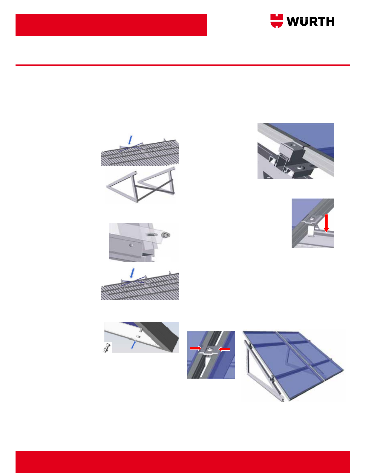
Installing Triangles:
Trianglescannowbemountedto
baserails.Todothisproperlyspace
trianglesonthebaserail,perthe
structuralsitespecicdrawings,and
attachwithcrossadapters.
Atotalof4crossadapterswillbe
usedtoattacheachtriangletothe
twobaserails.
Clickcrossadaptersonto
railwiththecurvedlipof
thecrossadaptersfacing
theC-Channelonthe
sidesofthetrianglebase
rails.Tightenthescrews
clockwise.See Figures
4.1 & 4.2
(Torque:6to8ft.lbs.)
Crossadapterswillbe
attachedonbothsidesof
eachtriangleforeachbase
rail.See Figure 4.3
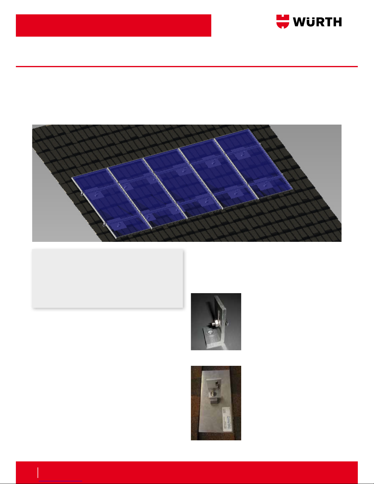
Nowthatonetriangleisattachedtothebaserails,continuetheprocesswith
therestofthetrianglesmakingsurethatthetrianglesareproperlyspaced
accordingtostructuralsitespecicdrawings.
Cross Rail Installation:
Next,modulemountingcrossrailswillbemountedtotheangledfaceofthe
triangles.See Figure 5.1
Thespacebetweenthecrossbar
clampsisabout½ofthemodule
heightinthecaseofframedmodules
thataremountedonend.Thespace
betweenthelowercrossbarclamps
andthebaserailisequaltoabout¼
ofthemoduleheight.See Figure 5.2
Pleasefollowtheinstructionsofthemodulemanufacturer.
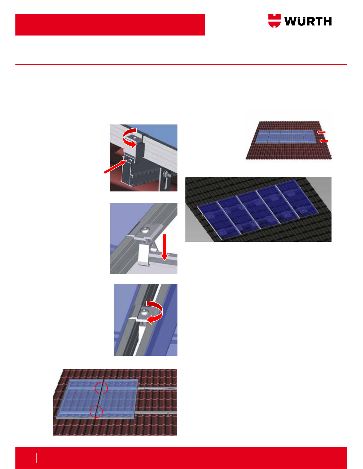
Now,positionthemountingrailonthecross
adapterclampsandhookthecrossbar
clampsinthemodulerackslots.Useacord
forprecisealignmentofmodulerackswith
oneanother.Useasplicetoattachmore
moduleracks.Afterallmoduleracksare
positionedcorrectly,fastenthescrewsofthe
crossadapterclampsbyturninghardware
clockwise.See Figure 5.3
(Torque:6to8ft.lbs.)
Tolineupseveralmodulemountingrailswithoneanother,slidethesplice
halfwayontotheassembledmodulemountingrailuntiltherivetonthesplice
stopstheinsertionofthesplice.
Thenplacetheopposingrailovertheexposedendofthespliceandpush
railstogetheragainsttherivet.½”gaporseparationbetweenrailsis
requiredforthermalexpansion.See Figure 5.4
SubjecttotechnicalchangesCopyright©2009HatiConSolar,LLC Page5of11
InstallingTriangles:
Trianglescannowbemountedtobaserails.Todothis
properlyspacetrianglesonthebaserail,perthe
structuralsitespecificdrawings,andattachwithcross
adapters.
Atotalof4crossadapterswillbeusedtoattacheach
triangletothetwobaserails.
Clickcrossadaptersontorailwiththecurvedlipofthe
crossadaptersfacingtheC‐Channelonthesidesofthe
trianglebaserails.Tightenthescrewsclockwise.
SeeFigures4.1&4.2
(Torque:6to8ft.lbs.)
Crossadapterswillbeattachedonbothsidesofeach
triangleforeachbaserail.
SeeFigure4.3
Nowthatonetriangleisattachedtothebaserails,
continuetheprocesswiththerestofthetriangles
makingsurethatthetrianglesareproperlyspaced
accordingtostructuralsitespecificdrawings.
Click
4.1
4.2
4.3
4.4
Fig. 4.1
Fig. 5.1
Fig. 5.2
Fig. 5.4
Fig. 5.3
Fig. 4.2
Fig. 4.3
Fig. 4.4
SubjecttotechnicalchangesCopyright©2009HatiConSolar,LLC Page6of11
CrossRailInstallation:
Next,modulemountingcrossrailswillbemountedto
theangledfaceofthetriangles.
SeeFigure5.1
Thespacebetweenthecrossbarclampsisabout½of
themoduleheightinthecaseofframedmodulesthat
aremountedonend.Thespacebetweenthelower
crossbarclampsandthebaserailisequaltoabout¼of
themoduleheight.
SeeFigure5.2
Pleasefollowtheinstructionsofthemodule
manufacturer.
Now,positionthemountingrailonthecrossadapter
clampsandhookthecrossbarclampsinthemodule
rackslots.Useacordforprecisealignmentofmodule
rackswithoneanother.Useasplicetoattachmore
moduleracks.Afterallmoduleracksarepositioned
correctly,fastenthescrewsofthecrossadapterclamps
byturninghardwareclockwise.
SeeFigure5.3
(Torque:6to8ft.lbs.)
Tolineupseveralmodulemountingrailswithone
another,slidethesplicehalfwayontothe
assembledmodulemountingrailuntiltheriveton
thesplicestopstheinsertionofthesplice.
Thenplacetheopposingrailovertheexposedendof
thespliceandpushrailstogetheragainsttherivet.½”
gaporseparationbetweenrailsisrequiredforthermal
expansion.
SeeFigure5.4
Note:Donotattempttothroughboltanysplices.The
splicewasdesignedtoallowthealuminumrailsto
expandandcontractunderthermalconditions.
5.1
5.2
5.3
5.4
Note:
Note:Donotattempttothrough-boltanysplices.Thesplicewas
designedtoallowthealuminumrailstoexpandandcontractunder
thermalconditions.
¼Module
Height ½ModuleHeight
Assembly Instructions
5Solar Mounting Sytem