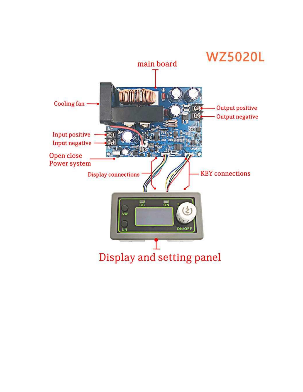
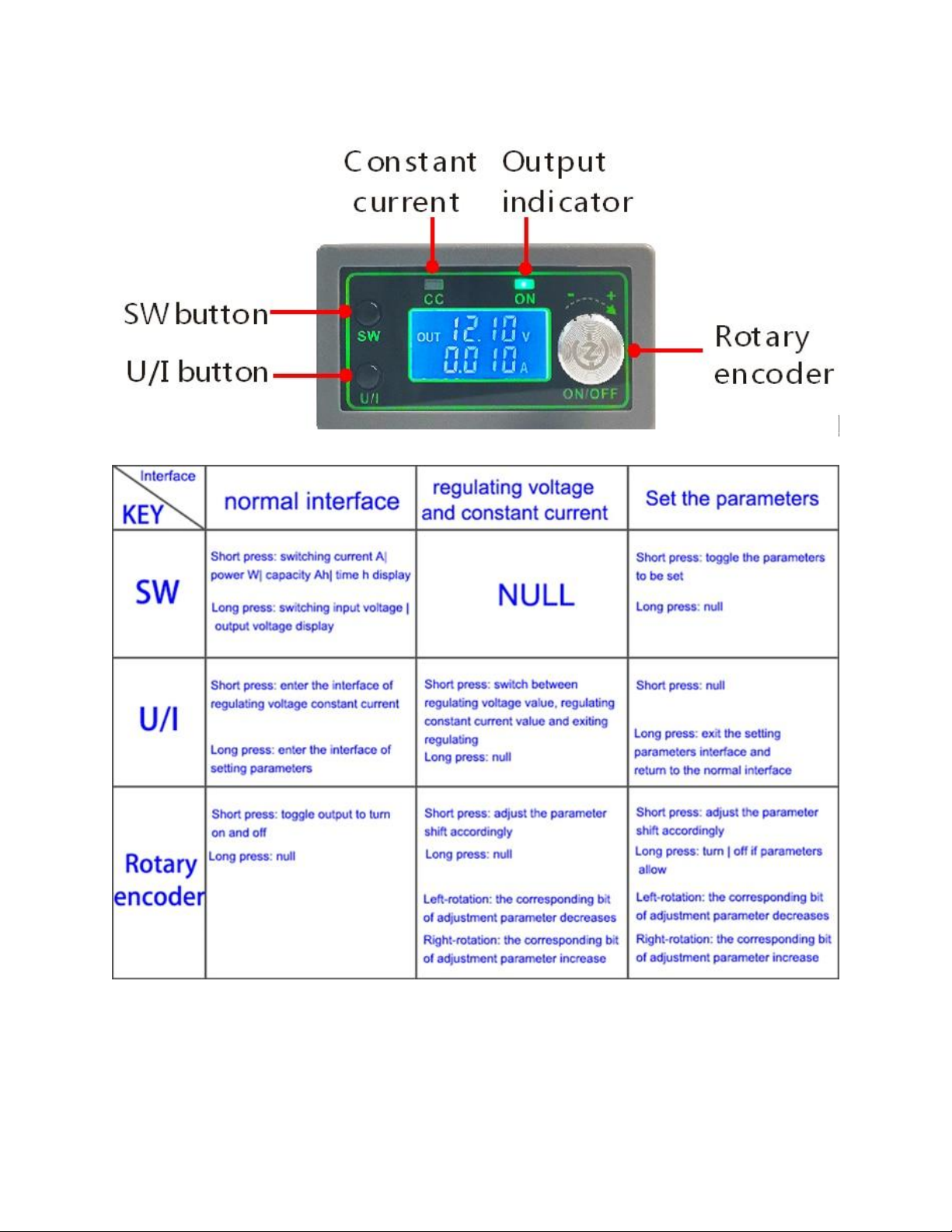
encoder left and right to adjust the major and minor.Short press the
rotary encoder to choose which bit of output voltage to set.After
setting, press U/I button 2 times to return to the normal interface.Or
automatically return to the normal interface after stopping operation for
10s.
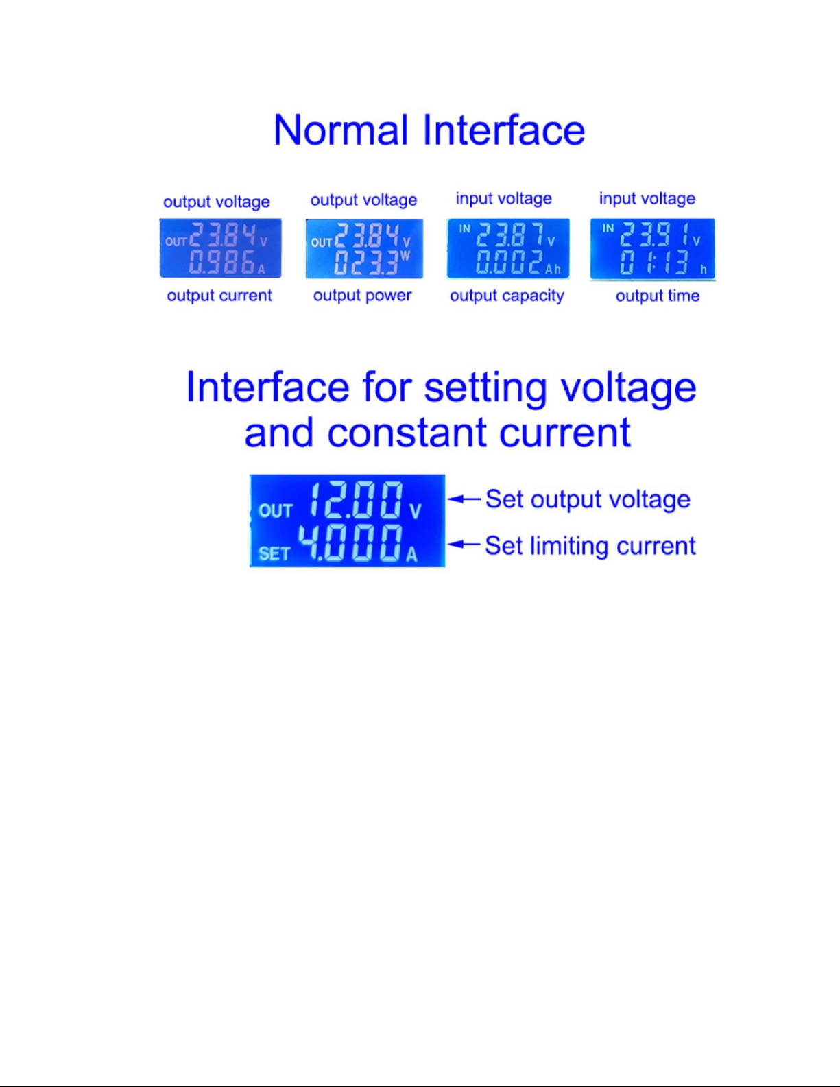
5.3. Set constant current value (that is, the maximum current value
allowed to output by the module) -- press U/I button in the normal
interface to enter the setting voltage constant current interface.Then
press U/I button and switch to setting constant current value. You can
see a bit of the setting constant current value flashing. Rotate the
rotary encoder left and right to adjust the major and minor.Short press
the rotary encoder to choose which bit to set the constant current
value.After setting, press U/I to exit the setting voltage constant
current interface and return to the normal interface.Or automatically
return to the normal interface after stopping operation for 10s.
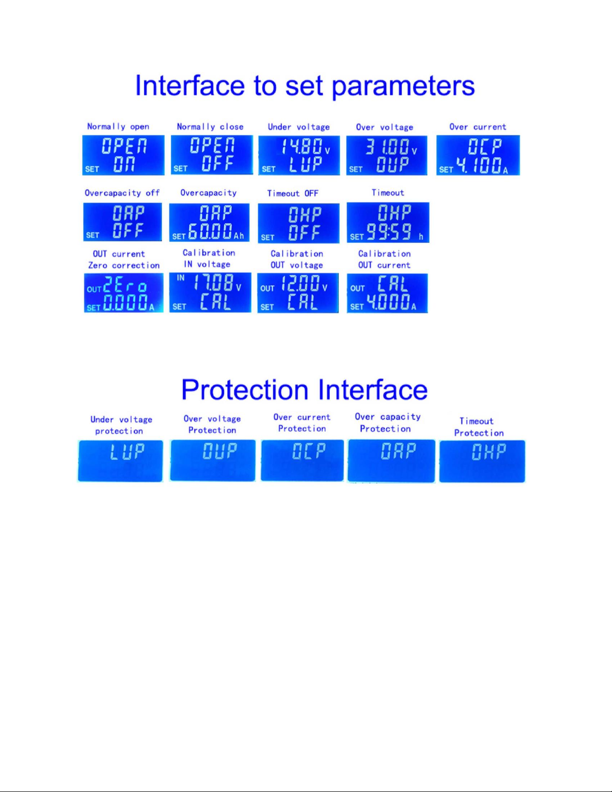
5.4. Set the default on/off state of module power-on -- long press U/I in
the normal interface to enter the parameter setting interface.You can
see that it shows "OPEN OFF" or "OPEN ON". "OPEN OFF" means
the output is turned OFF by default when power is ON, and "OPEN
ON" means the output is turned ON by default when power is
ON.Long press rotate encoder to switch two states.After setting, long
press U/I to return to the normal interface.
5.5. Setting of protection parameters on state and threshold -- long
press U/I to enter the parameter setting interface in the normal
interface.Press SW until the protection you want appears.LUP --
undervoltage protection threshold;OUP -- overvoltage protection
threshold;OCP -- overcurrent protection threshold;OAP -- ultra-
capacity protection threshold;OHP timeout protection threshold.Short
press rotate encoder to select which bit you want to set the protection
parameter.Long press the rotary encoder to set the protection
parameters on or off (only timeout protection and supercapacity
protection can be set to turn on/off, and other protection parameters
are turned on by default.).Rotate the encoder left and right to make
the parameters bigger and smaller.After setting, long press U/I to