Wylie Spray Wyng II Programming manual

Operator’s & Parts Manual
Spray Wyng II
Printed In The USA — Specications & Design Subject To Change Without Notice
1-1-19 08-13R4

This is a limited warranty. It covers products manufactured by WYLIE Mfg. Co. The Warrantor is WYLIE Mfg. Co., 702 E.
40th St., Lubbock, TX 79404 USA. The duration of the warranty for WYLIE manufactured equipment and products (excluding
polyethylene tanks) is for one year from date of delivery to the carrier. The Warrantor warrants to the Buyer that the product(s)
sold hereunder are free from defects to material and workmanship, under normal use and service, in the hands of the original
buyer.
If goods are defective, the defective goods will be replaced with identical goods. If identical goods are not available, the Buyer
may elect to receive a refund of the purchase price for the defective goods, or the Buyer may order similar goods. The damage
for defective goods shall not exceed the purchase price of the defective goods. No allowance shall be made for labor
or expense or repairing goods without prior approval in writing by the Warrantor. The Buyer’s remedy under this warranty
does not include incidental or consequential damages.
For products not manufactured by the Warrantor, the Warrantor warrants these products to the extent of the warranties of their
respective manufactures. There are no warranties which extend beyond this limited warranty, including the implied
warranty of merchantability. Dealers or representatives shall not make any representation in regard to particular goods except
as authorized by the Warrantor through a written warranty accompanying those particular goods.
WYLIE Mfg. Co., and its divisions, “Wylie Spray Centers,” in each location, requires as a condition of sale and coverage by its
LIMITED WARRANTY that all equipment sold by it be used in accordance with the instructions and specications of the Warrantor.
This requirement is in addition to the LIMITED WARRANTY.
Polyethylene and berglass tanks – These tanks are warranted for the storage and transport of water, herbicide solutions
(on farm), liquid fertilizer and liquid feed. Such tanks should not be used for the storage of any bulk herbicide (undiluted). Any
such use will render this warranty void.
In addition, the Warrantor makes no warranty with regard to bulkhead tank ttings used in connection with tanks containing bulk
herbicides and the use of any such ttings sold by the Warrantor or any WYLIE dealer in connection with tanks containing bulk
herbicides is improper.
Chemical Incompatibility – The Warrantor does not make any recommendations or warranties regarding chemical compatibility.
WYLIE shall not be liable for any damages due to chemical incompatibility, and any Buyer or user should rely solely on written
information furnished by the chemical manufacturer regarding chemical compatibility.
No employee of WYLIE Mfg. Co., or its representatives, agents or dealers, is authorized to vary the terms of this limited
warranty.
This equipment was carefully designed and manufactured to give you dependable service. To insure ecient operation of
this equipment, please read this operator’s manual carefully. Check each item and acquaint yourself with the adjustments
required to maintain optimum performance and operation. Remember, this equipment’s performance depends on
how you operate and care for it!
At the end of each season, thoroughly clean and inspect your equipment. Preventive maintenance saves time and pays
dividends. Your nearest Wylie Spray Center has original equipment parts which assure proper t and best performance.
Record your equipment’s model and serial numbers and the date you purchased this equipment in the space below.
Have this information available when you order parts or attachments.
Model Number:
Serial Number:
Date Purchased:
A Message To The Owner And Operator
Limited Warranty
Disclaimer of Warranty
Warranty Information

Wylie Manufacturing Company
702 E. 40th St.
Lubbock, TX 79404
Ph. 888-788-7753
Spray Wyng II Sprayer
Date of Purchase
Model Number
Tank Serial Number
Trailer Serial Number
Boom Serial Number
Pump Model
Wylie Invoice Number
Owner’s Name
Address
City State Zip
Phone
Email
Dealer
Owner’s Signature
Must be returned within 10 days to validate the warranty.
Use of Applicator:
Row Crop Cotton
Small Grain Pasture
Other
Owner Registration
-- Or Register Online --
Go to: www.wyliesprayers.com

.

1
Table Of Contents
Safety Issues ...........................................................................................................................................................2 - 3
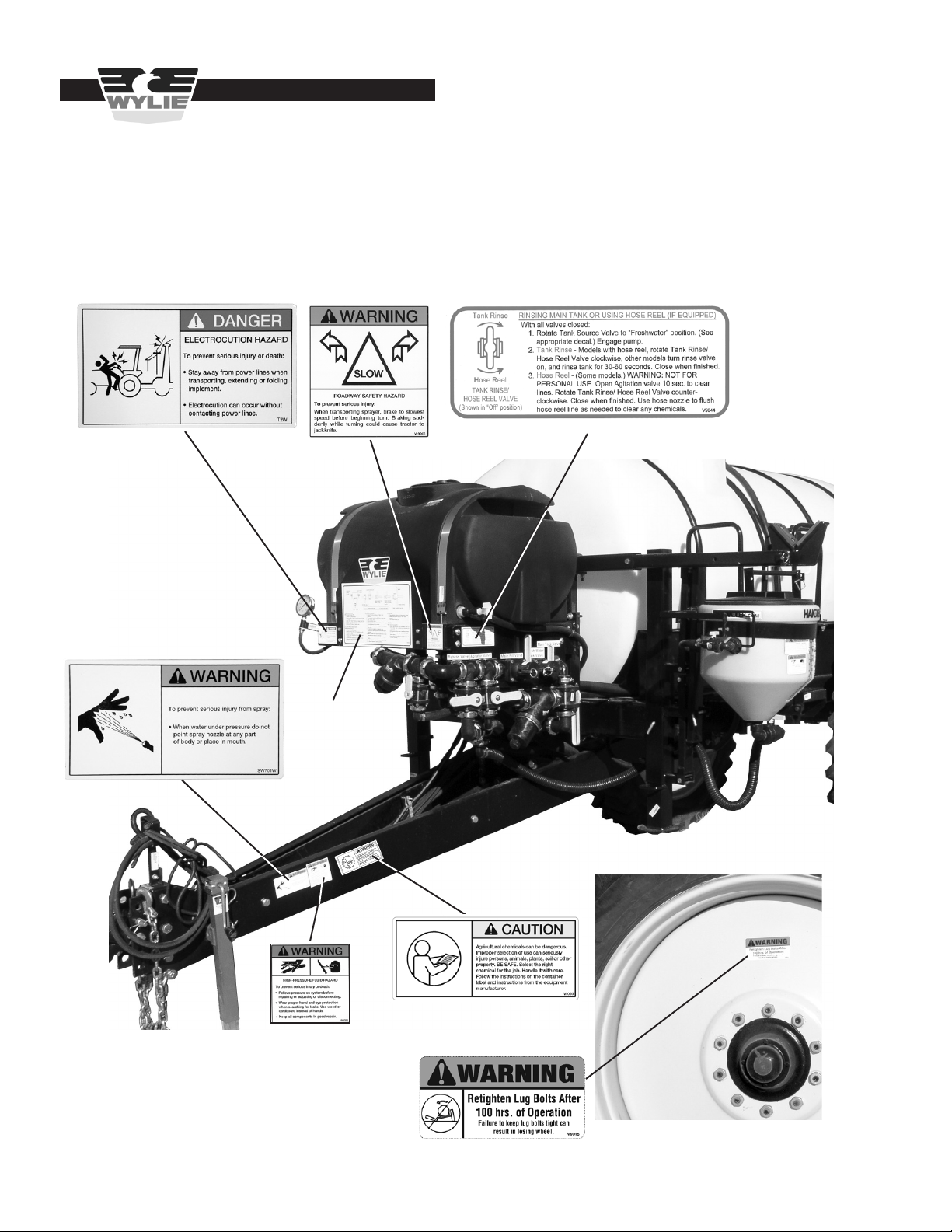
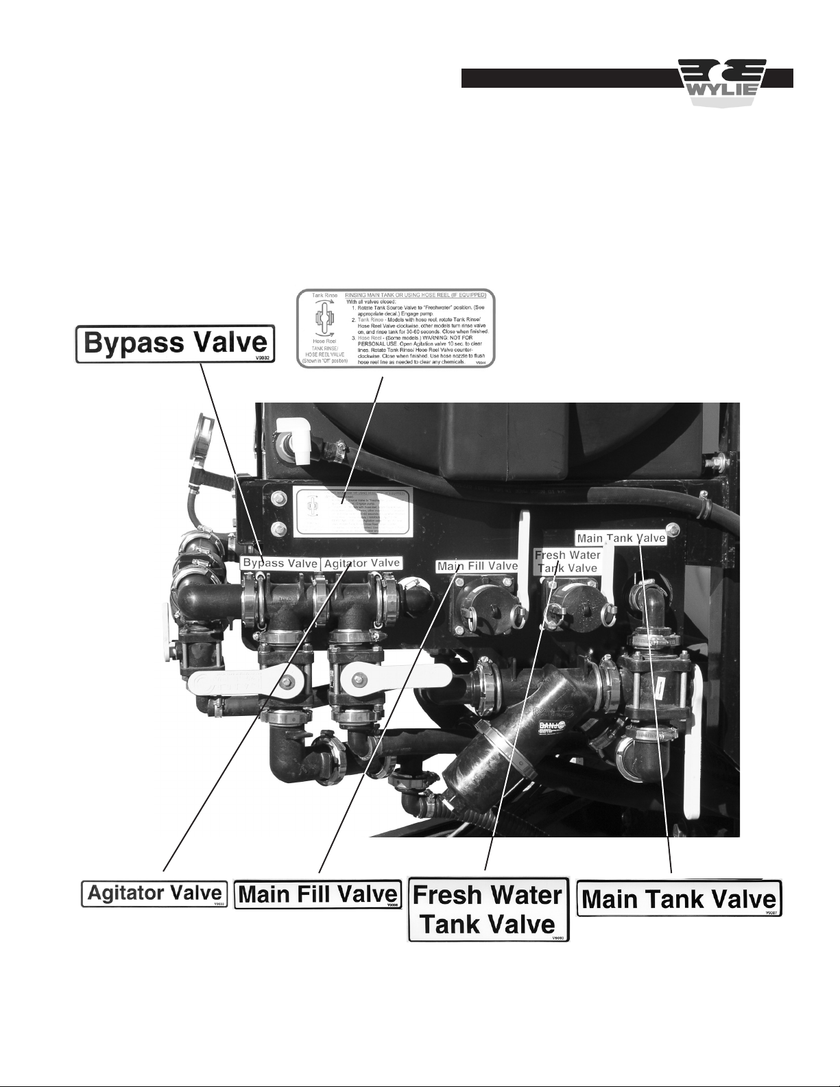
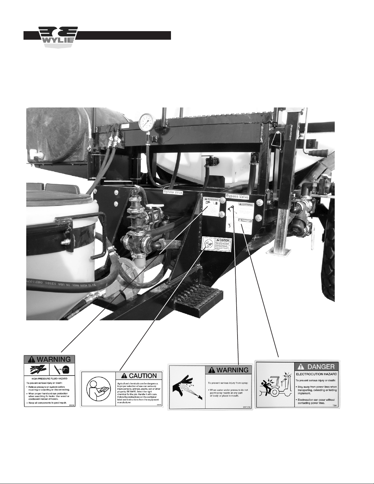
Safety Decals & Placement .....................................................................................................................................4 - 7
Introduction ................................................................................................................................................................... 8
Inspection & Setup ................................................................................................................................................9 - 10
Boom Operation .................................................................................................................................................. 11 - 13
Sprayer Operation ...............................................................................................................................................14 - 22
Maintenance ............................................................................................................................................................... 23
Boom Adjustment ................................................................................................................................................24 - 30
Trailer Adjustment ................................................................................................................................................29 - 30
Lubrication ...........................................................................................................................................................30 - 31
Troubleshooting Guidelines .................................................................................................................................32 - 34
Repair Parts.........................................................................................................................................................33 - 60
Spray Wyng II Center Section .......................................................................................... 34
Spray Wyng II Suspension ............................................................................................... 35
Spray Wyng II Primary Section ........................................................................................ 36
Spray Wyng II Boom Plumbing ........................................................................................ 36
Spray Wyng II Secondary Section .................................................................................... 37
Spray Wyng II Breakaway Section ................................................................................... 38
Spray Wyng II Hi-Lift Linkage ........................................................................................... 39
Spray Wyng II Control System .........................................................................................40
Spray Wyng II Hydraulic Hose Routing ............................................................................ 41
W1510 VersaTrail Trailer .................................................................................................. 42
W1501-16 1,600 Gal. Spray Trailer .................................................................................. 43
SW-1000-SA 1,000 Gal. Single Axle Trailer ..................................................................... 44
SW-1000-ST 1,000 Gal. Tandem Axle Trailer ................................................................... 45
W1515 VersaTrakr Trailer (through 2018) ........................................................................ 46
VersaTrakr Articulated Hydraulic System .........................................................................47
VersaTrakr/VersaTrail Wheels and Axle ........................................................................... 48
VersaTrakr, VersaTrail Pump Kit ...................................................................................... 49
1600 Pump Kit .................................................................................................................. 50
VersaTrakr, VersaTrail, 1600 Tank Plumbing ...................................................................51
VersaTrakr, VersaTrail, 1600 Trailer Plumbing ..........................................................52 - 53
1,000 Tandem/Single Axle Trailer Plumbing ..............................................................54 - 55
Handler™ Mix Assembly/1600 Agitator Assembly ............................................................ 56
Hydraulic System ............................................................................................................. 57
Raven Boom Valves ......................................................................................................... 58
Ace 304 Pump .................................................................................................................. 59
Ace 206 Pump .................................................................................................................. 60
Table of Contents

2
Safety Precautions
Be alert when you see the above symbol in the manual. It warns of a hazard
which might lead to injury. It means: Attention! Become alert! Your safety is
Involved!
Three (3) words (Danger, Warning, and Caution) are associated with this symbol.
DANGER – Indicates a hazardous situation, which, if not avoided, will result in death or serious injury. This signal word
is to be limited to the most extreme situations.
WARNING – Indicates a hazardous situation, which, if not avoided, could result in death or serious injury.
CAUTION – Indicates a hazardous situation, which, if not avoided, may result in minor or moderate injury.
NOTICE – Indicates information considered important, but not hazard-related (e.g., messages relating to property damage).
SAFETY INSTRUCTIONS - Indicates a type of safety sign where specic safety-related instructions or procedures are described.
Before Use
Do not operate sprayer until this manual has been read and understood!
* Thoroughly read and understand all instructions before operating this sprayer. If you have questions,
please contact Wylie Manufacturing, 702 E. 40th St., Lubbock, TX 79404, (888) 788-7753.
You can also contact your nearest Wylie Spray Center.
* Place an emblem on the rear of the unit prior to driving on open roads.
* Always wear safety goggles, chemical resistant apron and rubber gloves when handling chemicals.
* Read and understand the chemical manufacturer’s safety guidelines on handling, mixing and application.
During Use
* Do not allow anyone to ride on sprayer during operation. Falling can cause injury.
* Reduce speed when crossing uneven or rough terrain.
* Always support the sprayer on parking stands and turn o tractor engine before making adjustments
or repairs.
Safety Issues

3
After Use
* Inspect sprayer for wear or damage.
* Ensure that all fasteners and ttings are tight.
* Flush tank and pump with fresh water. Dispose of ush water using appropriate means.
* Carry out maintenance and/or lubrication procedures as outlined in this manual.
Always
* Keep hands, feet and clothing away from moving parts.
* Wear protective clothing and gloves when working with the hydraulic system.
* Escaping hydraulic uid under pressure can penetrate skin causing serious injury:
– Do Not use hands to check for leaks in hydraulic system, use cardboard or paper.
– Stop tractor engine and relieve pressure before connecting or disconnecting lines.
– Tighten all connections prior to starting engine or pressurizing line.
– If any uid is injected into the skin, obtain medical treatment immediately to avoid gangrene.
Operator’s Instructions
* Securely fasten seat belt if tractor is equipped with a (ROPS).
* When possible, avoid operating the tractor near ditches, embankments and holes.
* Reduce speed when turning, crossing slopes and on rough, slick or muddy surfaces.
* Be aware of where you are going at all times; especially at row ends, roads and around trees.
* Do not permit others to ride.
* Operate tractor smoothly – no jerky turns, starts and stops.
* Hitch only to the drawbar and hitch points recommended by the tractor manufacturer.
* When tractor is idle, engage brakes and park lock securely.
* Tighten lug bolts before transporting and after the rst ve miles.
* Limit transport speed to 25 mph.
Safety Issues

4
Safety Decals & Placement
Safety Issues
VersaTrail/1600 Spray Trailer
Decal #V9055
Decal #T2W
Decal #V9043
Decal #V9003 Decal #V9044
Decal #SW701W
Decal #SW700
or 888-788-7753 to order safety decal
or manual replacements.

5
Safety Issues
Decal #V9010
Decal #V9008 Decal #V9007
Safety Decals & Placement
VersaTrail/1600
Spray Trailer
Decal #V9033
Decal #V9032
Decal #V9044
replacements.

6
Safety Issues
1,000 Gal. Single/Tandem Axle
Safety Decals & Placement
Decal #SW700 Decal #SW701W Decal #T2W
or manual replacements.
Decal #V9055

7
Safety Issues
Safety Decals & Placement
Spray Wyng II Boom
Decal #SW202
Decal #V9006
or 888-788-7753 to order safety decal
or manual replacements.

8
The Wylie Spray Wyng II Sprayer is built of the nest materials and expert workmanship to provide you with years of
reliable service. The Spray Wyng II is built in ve sizes, 60’, 80’, 90’, 100’ and 108’ for trailer mounted congurations. All
sizes are available for the VersaTrail and 1600 models. The 1,000 gallon models carries the 60’ boom.
This manual explains where and how to make necessary adjustments to your sprayer for safe and proper operation.
Thoroughly read and understand the contents of this manual before operating your sprayer. If you have questions or do
not understand particular items, contact your nearest Wylie Spray Center or call Wylie Manufacturing at (888) 788-7753.
Please keep this manual handy to answer questions you may have as they arise.
Pay Particular Attention To All Safety Suggestions – Their purpose is to assure safe operation of the
sprayer and prevent injury or damage to yourself or the sprayer.
Note: In all references to the boom and trailer, left and right are determined by standing behind the sprayer
and looking toward the tractor.
Introduction
Introduction

9
Inspection & Setup
Inspection & Setup
Spray Trailers
The Spray Wyng II boom can be mounted on a variety of
trailers including the VersaTrail, 1,600 gallon, the 1,000
gallon tandem axle, the 1,000 gallon single axle.
The VersaTrail, 1,600 and 1,000 gallon tandem/single axle
are delivered set up and should need no further assembly.
The sprayer was tested at the factory, but the sprayer
should be checked for any damage during shipment. It
is important to check the lug bolts upon delivery and after
100 hours of operation. Tighten as necessary.
Attach the trailer tongue to the tractor drawbar. The sprayer
should be leveled by adjusting the hitch in the trailer tongue.
Lower the jack, unpin the hitch from the tongue and raise
or lower the tongue as needed to level the sprayer. Pin the
hitch in the appropriate holes.
Figure A1
Check and Tighten Lug Bolts
All Spray Trailers:
The Spray Wyng II Boom requires only two tractor remote
circuits. One circuit powers the pump and while the other
circuit powers all the boom functions. The Spray Wyng II,
from the factory, is set up to operate on open-center and
closed-center hydraulic systems without any modications.
Enhanced performance is available on closed-center sys-
tems with a eld modication. Call Wylie Customer Service
for details. (888-788-7753).
Transport Lights
The Spray Wyng II is equipped with red and amber
transport lights that function in the same way as the tractor’s
ashing lights. Make sure the sprayers lights are plugged
in and operating before transporting the sprayer on any
public road.
Figure A2
Adjust Hitch To Level Sprayer
Figure A3
Hydraulic Hoses
Hitch Pins
< Electrical
Connection
< Pump Hyd.
Hoses
< Lift/Tilt/Fold
Hyd. Hoses
Lift/Tilt/Fold >
Control Cable
Spray >
Control Cable
Figure A4
Transport Lights

10
Inspection & Setup
Figure A5
Boom/Spray Control
Figure A6
Boom and Sprayer Controls
Installing Boom Controller
The Spray Wyng II is equipped with an integrated boom
control that mounts with the Raven SCS450 controller. The
upper boom section controls the lift, fold, and tilt functions
of the boom, while the lower spray section programs and
controls the volume and pressure of the spray.
Most tractor manufacturers oer a control mount. The
boom/spray control can be installed on a manufacturer’s
mount or can be installed at the operator’s preferred
location.
Refer to the Raven Owner’s Manual for instructions on
properly wiring the Raven controller.
The Wylie boom control box is equipped with a pair of hot/
ground wires and a wiring harness for the sprayer. Attach
the red wire to a constant 12 volt source and the black wire
to a ground source. The wiring harness should be routed
outside the tractor cab to the sprayer.

11
Boom Operation
Boom Operation
Unfolding the Boom
Assure that the area is clear of all people before unfold-
ing boom. Failure to do so could cause bodily injury
to anyone hit by an unfolding boom.
The rst time the boom is operated should be in an open
area so that any air in the hydraulic system can be purged
from the lines. Air in the lines can cause erratic or exces-
sive speed in unfolding. Move the sprayer to a at area
with sucient clearance to unfold the boom.
Chains must be removed before unfolding boom.
Failure to do so will result in damage to the boom.
Remove the chains from the boom before unfolding.
The transport locks must be removed from the “Hi-Lift link-
age” to allow the boom to lower to the operating position.
The boom hydraulics are activated by the tractor hydraulic
system, but controlled by the boom control panel. The
tractor remote should be set to run at ¼ to ½ speed and
should be shifted to the pressure detent position for normal
operation. Activate the boom lift switch on the boom control
panel (as shown in Fig. B2) to raise the boom and allow
the locks to be removed. Remove the Hi-Lift locks from
the cylinders and store on the upper link. When moving
from eld to eld, return the locks to the transport position
and lower the boom onto the locks to reduce strain on the
boom and lift components.
Figure B1
Boom Chains
Figure B3
Hi-Lift Lock Installed Hi-Lift Lock Stored
The boom control panel contains three major sections:
the left boom controls, the right boom controls and the
combined boom controls.
With the boom chains removed and the sprayer in an open
area, the boom is ready to be unfolded. It is possible that
air could be in the hydraulic lines the rst time the boom
is unfolded. Note: Be aware that air in the lines can cause
the boom to unfold erratically or with excessive speed.
Figure B2
Raising Boom
Figure B4
Boom Control Panel
Hi-Lift Lock >
< Hi-Lift Lock
< Boom Rest
Boom Chain >

12
Unfold the inner wings of the right boom by engaging
the right boom fold switch. Repeat with the left boom
switch.
Activate the right outer fold switch to fold the right outer
wing out. Repeat with the left outer wing.
Boom Operation
Unfold and fold the boom several times to purge any air
from the hydraulic lines. After the initial fold/unfold cycle,
the “combined” control can be used to fold/unfold both
wings simultaneously.
Tilting the Boom
The boom can be tilted by activating the tilt switch on either
wing. Push the switch up to raise the wing; push the switch
down to lower the wing. The combined tilt switch will tilt
both wings simultaneously.
Push the tilt switch up for each boom to raise the boom
out of the boom rests. The individual boom switches on
the control panel operate in the desired direction of travel
i.e., push the fold switch toward the outside of the panel
to fold the boom out, or push the tilt switch up to raise the
boom section.
Figure B6
Unfolding Right Boom
Figure B5
Activating Tilt Switch Raises Wing
Figure B7
Unfolding Right Breakaway Section
Figure B8
Unfolding Both Wings With “Combined” Switch
Figure B9
Activating Tilt Switch Raises Wing

13
Folding One Side of the Boom
From time to time it may be necessary to fold one wing
and spray with the rest of the boom. Use the single wing
controls to fold the outer wing, then tilt the wing so that
the folded section will clear the trailer tire as it is folded.
Fold the primary wing by pushing the individual wing fold
switch “in”. Cradle the boom in the boom rest when folded
by tilting the boom “down”.
Figure B10
Tilted Left Wing
Figure B14
Spray Wyng II Boom Sections
Sprayer Operation
Figure B11
Wing In Boom Rest
Figure B12
Folded Wing
When one wing is folded, the other wing will probably drop
since the boom is then unbalanced. Tilt the unfolded wing
“up” to bring it back to level. Single wing spraying should
only be for short distances, at slow speeds.
With the boom unfolded, check along the length of the
boom to assure that the boom is straight. If one or more
sections of the boom is not straight, refer to pages 24-25
for instructions on how to straighten the boom.
Figure B13
Aligned Boom
boom
sections
should
be
aligned
Center Section Inner Wing Outer Wing Breakaway
< Boom Rest

14
Sprayer Operation
VersaTrail, 1600 Manifold
The VersaTrail and 1600 are equipped with a valve mani-
fold to make lling, mixing and cleaning easier and safer.
An instructional decal is included as well.
1. Tank Source Valve -- controls main tank and fresh water tank
2. Fresh Water Tank Fill Valve
3. Main Tank Fill Valve
4. Fresh Water Hygiene Valve
5. Agitation Valve
6. Return Valve
7. Boom Flush Valve
8. Boom Line Strainer (discharge)
9. Supply Line Strainer (suction)
10. Handler™ Drain Valve
11. Handler Rinse Valve
12. Jug Rinse Valve (not shown)
The VersaTrail main tank is equipped with valves below the
sump. These valves will usually only be closed when repairs
to the hoses are required. For operation, the valves should be
open. The main tank valve is a three-way valve; vertical is “o”,
handle rear (shown) is “normal ow”, handle front is “drain” (with
plug removed).
1. Main Tank Valve
2. Main Tank Fill Valve
3. Return Valve
4. Agitation Valve
5. Supply Line Strainer (suction)
6. Boom Flush Valve
Initial Sprayer Check-out
Load about 300 gallons of clean water into the spray tank.
Add a few gallons of water to any other tanks such as the
Handler or fresh water tank.
VersaTrail, 1600 -- To add water to the spray tank, remove
the cap from the Main Tank Fill quick coupler and couple
the supply hose. Open spray tank ll valve (leave other
valves closed) (Figure C1). Open the supply line and add
desired amount of water.
1,000 Field Sprayer -- To add water to the spray tank,
remove the cap from the Main Tank Fill quick coupler and
couple the supply hose. Open main tank ll valve and main
tank valve (leave other valves closed) (Figure C3). Open
the supply line and add desired amount of water.
Do not add any chemical to any tank until the sprayer
has been fully checked for leaks.
Sprayer Operation
Figure C1
VersaTrail, 1600 Manifold
Figure C2
VersaTrail, 1600 Open Tank valves
Agitator >
Return >
Main >
2
3
4
5
6
7
8
910
12
1
11
Figure C3
1,000 Field Sprayer Manifold
2
3
4
5
6
1
< Instructional Decal

15
the agitator ball valve on the spray tank. Engage the pump
and open the valves to bring the boom up to operating
pressure. With the boom spraying, check all plumbing
connections for leaks. Make sure that all tips are spraying
a uniform pattern.
Note: The return valve should be opened fully only
when mixing chemical in the main tank. This valve can
be partially opened during spraying to control the pump
pressure. Fully opening during spraying will prevent
the boom from achieving operating pressure.
Turn the pump o, close the spray tank ball valve and clean
out the main strainer.
Filling The Fresh Water Tank
Only potable water should be added to the fresh wa-
ter tank. Addition of contaminated water could cause
bodily injury when used for washing hands, face and
eyes.
VersaTrail, 1600 -- Remove the cap from the fresh water
tank ll valve and couple the supply line. Open the fresh
water tank ll valve and open the supply line. When the
tank is full, close the fresh water tank ll valve before dis-
connecting the supply hose.
1,000 Field Sprayer -- The fresh water tank is lled by
inserting a supply hose through the llwell on top of the
tank.
Figure C5
Flushing boom with clean water
Figure C6
Installing tip screen and spray tip
Open ball valves to allow water to gravity ow through
the system. Check for any leaks. Close all ball valves
except the main ball valve between the spray tank and
the pump.
It is important to ush the boom before installing the spray
tips.
Note: The hydraulic uid ow supplying the pump must
be set the rst time the pump is engaged and anytime a
dierent hydraulic circuit or tractor is used. Before engag-
ing the pump, turn the hydraulic adjustment to its lowest
setting for that particular circuit. With the return and boom
valves turned o, engage the hydraulic lever and slowly
increase the hydraulic uid ow until the boom pressure
gauge reads not more than 100 psi.
Set the controller to manual. Activate the valve for each
boom section so that water is ushed through open nozzle
bodies. Turn the pump o once the boom is ushed. See
Figure C5.
Install the spray tips and tip screens in each nozzle body.
Note: Some sprayers may be equipped with double line
strainer, therefore, making tip screens unnecessary. Open
Figure C4
Adjusting hydraulic uid ow
Sprayer Operation

16
Sprayer Operation
The fresh water tank can be used for ushing the pump
and boom as well as supplying hygiene water for washing
hands, face and, if necessary, eyes.
Open the fresh water hygiene valve as needed to wash
hands, face or to ush eyes if contacted with chemical.
Figure C7
Filling Fresh Water Tank
< Open Fresh Water
Tank Valve
Fresh Water >
Supply Line
Figure C8
Washing Hands From Fresh Water Tank Faucet
Loading Spray Material Into The
Sprayer
Always wear protective clothing, i.e. apron, face shield,
gloves and respirator, when handling any chemicals.
Failure to do so will risk chemical exposure to your
body resulting in sickness, injury or possibly death.
Spraying solution can be loaded by either lling with a pre-
mixed solution or mixing the chemical and carrier on the
sprayer. Most trailer mounted sprayers have a Handler™
mix tank mounted on the trailer.
Remove the cap from the “Quick Fill” coupling on the Main
Fill valve and attach the supply hose to the coupling. Open
the main ll ball valve and the supply line. Fill the spray
tank with water, fertilizer, etc., less the amount of chemical
to be added.
Handler tank should always be empty except when
adding chemical to the sprayer. Raising and lower-
ing the tank with chemical is dangerous and greatly
increases the possibility of chemical exposure to your
body resulting in sickness, injury or possibly death.
Figure C9
Filling Spray Tank
< Supply Line Valve
< Closed Main
Tank Valve
< Open Main Fill Valve
Table of contents
Other Wylie Paint Sprayer manuals
Popular Paint Sprayer manuals by other brands

Titan
Titan Focus 500 operating manual

Alfalaval
Alfalaval Toftejorg SaniMicro instruction manual

Central Pneumatic
Central Pneumatic PAINT SPRAY GUN 30224 Assembly and operating instructions

Spraying Systems
Spraying Systems TeeJet TECHNOLOGIES BoomPilot installation manual

Foamit
Foamit TU-25N Operation manual

Power Stroke
Power Stroke PSL1PS11 Operator's manual

FLORABEST
FLORABEST 280272 Operation and safety notes

Central Pneumatic
Central Pneumatic 2471 Assembly and operating instructions

Salt Dogg
Salt Dogg 6190120 Installation & operator's manual

R+M Suttner
R+M Suttner ST-73.1 user manual

Emist
Emist EM360 quick start guide

OneTech
OneTech NT-105 Operation manual