Wylie Row Wyng Programming manual

Operator’s & Parts Manual
Row WyngRow Wyng
Printed In The USA — Specications & Design Subject To Change Without Notice!
6-1-08 01-017R2

This is a limited warranty. It covers products manufactured by WYLIE Mfg. Co. The Warrantor is WYLIE Mfg. Co., 702 E. 40th
St., Lubbock, Texas 79404 USA. The duration of the warranty for WYLIE manufactured equipment and products (excluding
polyethylene tanks) is for one year from date of delivery to the carrier. The Warrantor warrants to the Buyer that the product(s)
sold hereunder are free from defects to material and workmanship, under normal use and service, in the hands of the original
buyer.
If goods are defective, the defective goods will be replaced with identical goods. If identical goods are not available, the Buyer
may elect to receive a refund of the purchase price for the defective goods, or the Buyer may order similar goods. The damage
for defective goods shall not exceed the purchase price of the defective goods. No allowance shall be made for labor
or expense or repairing goods without prior approval in writing by the Warrantor. The Buyer’s remedy under this warranty
does not include incidental or consequential damages.
For products not manufactured by the Warrantor, the Warrantor warrants these products to the extent of the warranties of their
respective manufactures. There are no warranties which extend beyond this limited warranty, including the implied
warranty of merchantability. Dealers or representatives shall not make any representation in regard to particular goods except
as authorized by the Warrantor through a written warranty accompanying those particular goods.
WYLIE Mfg. Co., and its divisions, “Wylie Spray Centers,” in each location, requires as a condition of sale and coverage by its
LIMITED WARRANTY that all equipment sold by it be used in accordance with the instructions and specications of the Warrantor.
This requirement is in addition to the LIMITED WARRANTY.
Polyethylene and berglass tanks – These tanks are warranted for the storage and transport of water, herbicide solutions
(on farm), liquid fertilizer and liquid feed. Such tanks should not be used for the storage of any bulk herbicide (undiluted). Any
such use will render this warranty void.
In addition, the Warrantor makes no warranty with regard to bulkhead tank ttings used in connection with tanks containing bulk
herbicides and the use of any such ttings sold by the Warrantor or any WYLIE dealer in connection with tanks containing bulk
herbicides is improper.
Chemical Incompatibility – The Warrantor does not make any recommendations or warranties regarding chemical compatibility.
WYLIE shall not be liable for any damages due to chemical incompatibility, and any Buyer or user should rely solely on written
information furnished by the chemical manufacturer regarding chemical compatibility.
No employee of WYLIE Mfg. Co., or its representatives, agents or dealers, is authorized to vary the terms of this limited
warranty.
This equipment was carefully designed and manufactured to give you dependable service. To insure ecient operation of
this equipment, please read this operator’s manual carefully. Check each item and acquaint yourself with the adjustments
required to maintain optimum performance and operation. Remember, this equipment’s performance depends on
how you operate and care for it!
At the end of each season, thoroughly clean and inspect your equipment. Preventive maintenance saves time and pays
dividends. Your nearest Wylie Spray Center has original equipment parts which assure proper t and best performance.
Record your equipment’s model and serial numbers and the date you purchased this equipment in the space below.
Have this information available when you order parts or attachments.
Model Number:
Serial Number:
Date Purchased:
A Message To The Owner And Operator
Limited Warranty
Disclaimer of Warranty
Warranty Information

Wylie Manufacturing Company
702 E. 40th St.
Lubbock, TX 79404
Ph. 888-788-7753
Row Wyng Sprayer
Date of Purchase
Model Number
Tank Serial Number
Frame/Trailer Serial Number
Pump Model
Wylie Invoice Number
Owner’s Name
Address
City State Zip
Phone
Email
Dealer
Owner’s Signature
Must be returned within 10 days to validate the warranty.
Type of Applicator:
Vegetable Cotton
Wheat Pasture
Other
Owner Registration
-- Or Register Online --
Go to: www.wyliesprayers.com

.

1
Table of Contents
Table Of Contents
Safety Issues .............................................................................................................................................................2-3
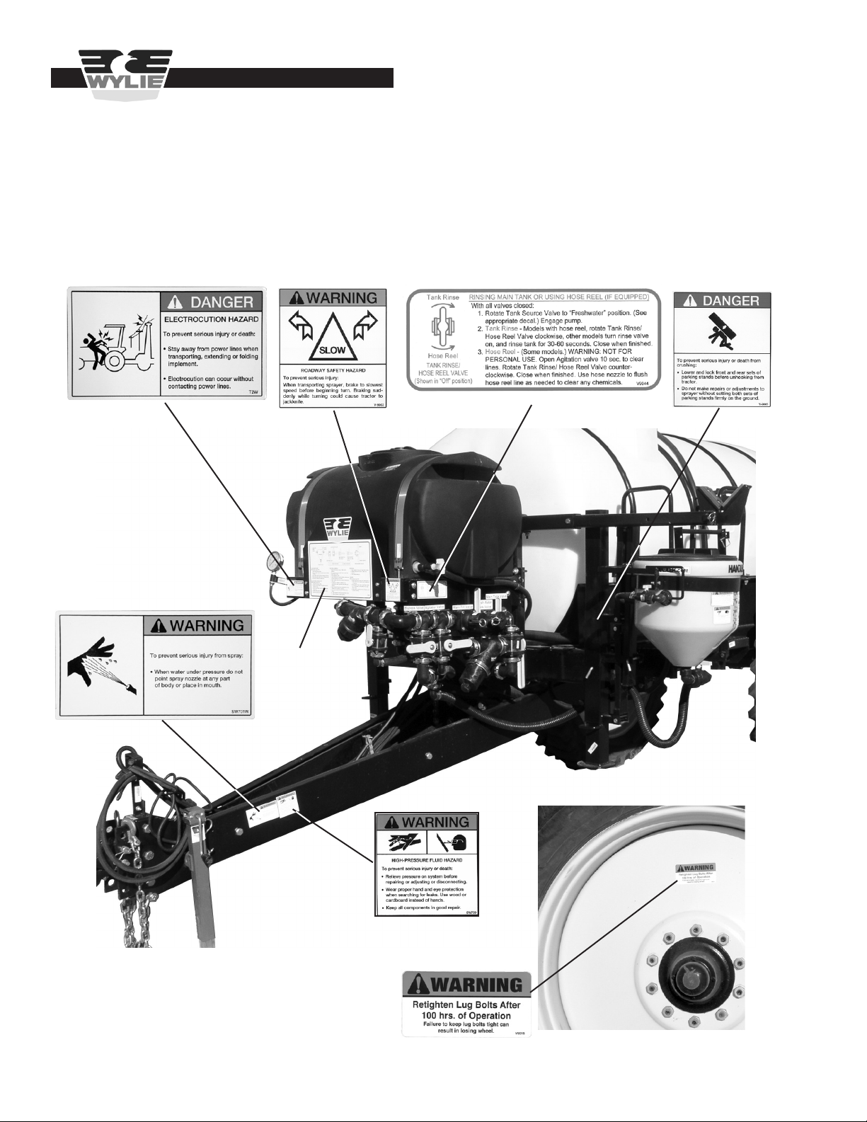
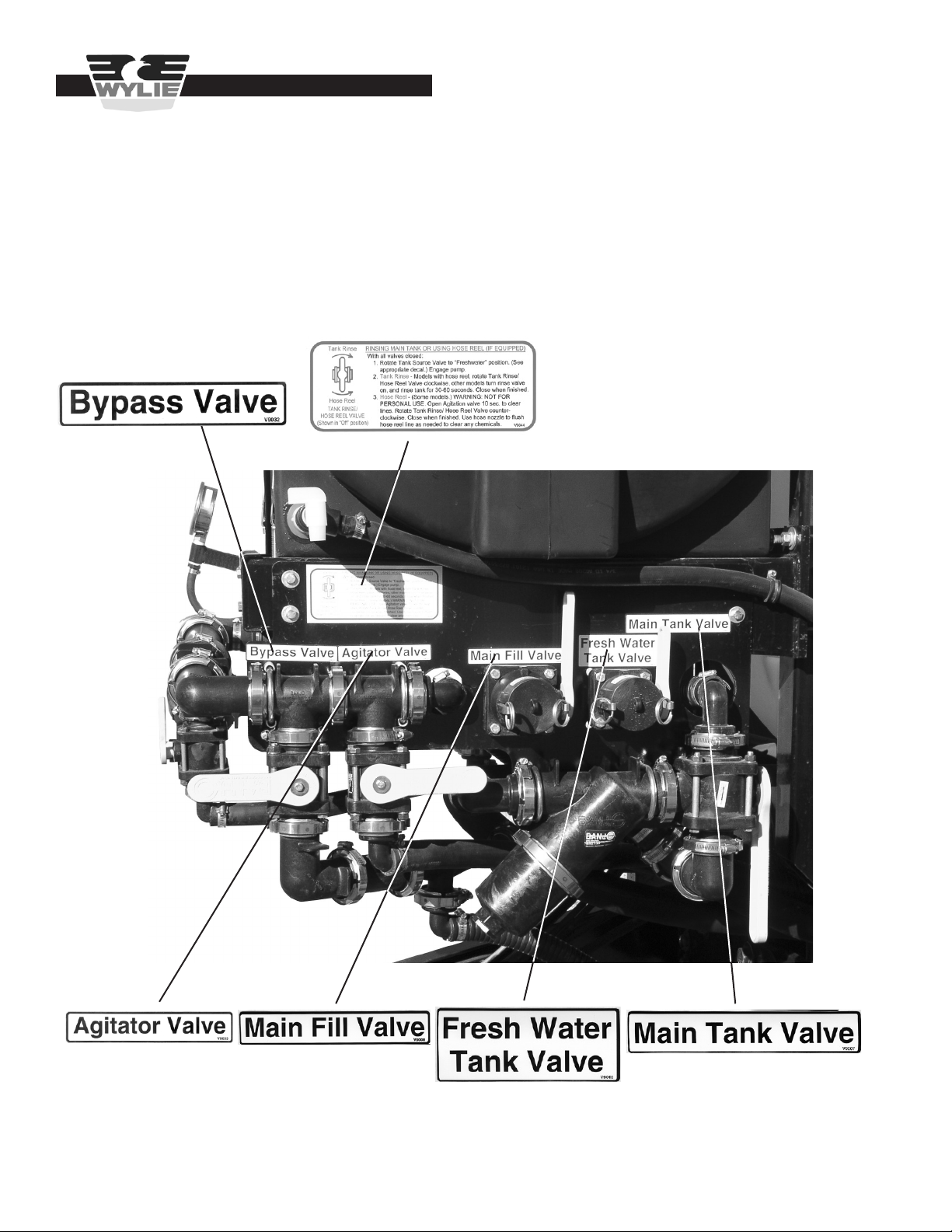
Safety Decals & Placement .......................................................................................................................................4-8
Introduction ................................................................................................................................................................... 9
Inspection & Setup ................................................................................................................................................10-12
Boom Operation ....................................................................................................................................................13-14
Sprayer Operation .................................................................................................................................................15-23
Maintenance ............................................................................................................................................................... 24
Boom Adjustment ..................................................................................................................................................25-26
Trailer Adjustment ..................................................................................................................................................27-28
Lubrication .............................................................................................................................................................28-29
Troubleshooting Guidelines ...................................................................................................................................30-32
Repair Parts...........................................................................................................................................................33-59
Row Wyng Carrier Frame Section .................................................................................... 34
Row Wyng Center Section ............................................................................................... 34
Row Wyng Primary/Secondary Section ........................................................................... 35
Row Wyng Boom Plumbing Kit ........................................................................................ 36
3 Point Fill Kit ................................................................................................................... 36
Carrier Plumbing and Pump ............................................................................................. 37
VersaTrakr Trailer ............................................................................................................. 38
VersaTrail Trailer .............................................................................................................. 39
VersaTrakr/WyngTrakr Articulated Hydraulic System .......................................................40
VersaTrakr/VersaTrail Wheels and Axle ........................................................................... 41
1,600 Spray Trailer ........................................................................................................... 42
Wyng Trakr Trailer ............................................................................................................43
1,000 Gal. Single Axle Trailer ........................................................................................... 44
1,000 Gal. Tandem Axle Trailer ........................................................................................ 45
EP-1000 HCS Trailer ........................................................................................................ 46
Hi-Lift Linkage .................................................................................................................. 47
VersaTrakr, VersaTrail, 1,600 Spray Trailer Plumbing .................................................48-51
1,000 Gallon Trailer Plumbing .....................................................................................52-53
Wyng Trakr Plumbing .......................................................................................................54
Handler™ Mix Assembly .................................................................................................. 55
1,600 Agitator Assembly ................................................................................................... 55
Mix n’ Fill Assembly .......................................................................................................... 56
3 Point Row Wyng Mount ................................................................................................. 56
Hydraulic and Flow Control .............................................................................................. 57
Hydraulic System ............................................................................................................. 58
Raven Boom Valves ......................................................................................................... 59

2
Safety Precautions
Be alert when you see the above symbol in the manual. It warns of a hazard
which might lead to injury. It means: Attention! Become alert! Your safety is
Involved!
Three (3) words are associated with this symbol. They are:
DANGER – Indicates an imminently hazardous situation which, if not avoided, likely will cause serious injury or death.
It is associated with the most extreme situations, typically for machine components, which, for functional purposes, can-
not be guarded.
WARNING – Indicates a potentially hazardous situation, which, if not avoided, could result in serious injury or death.
Relates to hazards that are exposed when guards are removed and alerts against unsafe practices.
CAUTION – Indicates a potentially hazardous situation which, if not avoided, may result in minor or moderate injury. It
may be used as an alert against unsafe practices.
Before Use
Do not operate sprayer until this manual has been read and understood!
* Thoroughly read and understand all instructions before operating this sprayer. If you have questions,
please contact Wylie Manufacturing, 702 E. 40th St., Lubbock, TX 79404, (888) 788-7753.
You can also contact your nearest Wylie Spray Center.
* Place a emblem on the rear of the unit prior to driving on open roads.
* Always wear safety goggles, chemical resistant apron and rubber gloves when handling chemicals.
* Read and understand the chemical manufacturer’s safety guidelines on handling, mixing and application.
During Use
* Do not allow anyone to ride on sprayer during operation. Falling can cause injury.
* Ensure the tractor has sucient weights to prevent tipping when spray tank is full.
* Reduce speed when crossing uneven or rough terrain.
* Always support the sprayer on parking stands and turn o tractor engine before making adjustments
or repairs.
Safety Issues

3
Safety Issues
After Use
* Inspect sprayer for wear or damage.
* Ensure that all fasteners and ttings are tight.
* Flush tank and pump with fresh water. Dispose of ush water using appropriate means.
* Carry out maintenance and/or lubrication procedures as outlined in this manual.
Always
* Keep hands, feet and clothing away from moving parts.
* Wear protective clothing and gloves when working with the hydraulic system.
* Escaping hydraulic uid under pressure can penetrate skin causing serious injury:
– Do Not use hands to check for leaks in hydraulic system, use cardboard or paper.
– Stop tractor engine and relieve pressure before connecting or disconnecting lines.
– Tighten all connections prior to starting engine or pressurizing line.
– If any uid is injected into the skin, obtain medical treatment immediately to avoid gangrene.
Operator’s Instructions
* Securely fasten seat belt if tractor is equipped with a (ROPS).
* When possible, avoid operating the tractor near ditches, embankments and holes.
* Reduce speed when turning, crossing slopes and on rough, slick or muddy surfaces.
* Be aware of where you are going at all times; especially at row ends, roads and around trees.
* Do not permit others to ride.
* Operate tractor smoothly – no jerky turns, starts and stops.
* Hitch only to the drawbar and hitch points recommended by the tractor manufacturer.
* When tractor is idle, engage brakes and park lock securely.
* Tighten lug bolts before transporting and after the rst ve miles.
* Limit transport speed to 25 mph.

4
Safety Decals & Placement
Safety Issues
VersaTrail/1600 Spray Trailer
Decal #V9015
Decal #T2W
Decal #V9043
Decal #V9003 Decal #V9005
Decal #V9044
Decal #SW701W
Decal #SW700

5
Safety Decals & Placement
Safety Issues
VersaTrakr/WyngTrakr Spray Trailer
Decal #SW700
Decal #V-9005
Decal #T3
Decal #SW701W
Decal #V9044
Decal #V9043
Decal #V9040
Decal #V9039
Decal #T2W

6
Safety Issues
Decal #V9010
Decal #V9008 Decal #V9007
VersaTrail/VersaTrakr/1600
Spray Trailer
Decal #V9033
Decal #V9032
Decal #V9044

7
Safety Issues
1,000 Gal. Single/Tandem Axle
Decal #SW700 Decal #SW701W Decal #T2W

8
Safety Decals & Placement
Decal #SW202
Decal #SW700 (3pt hitch) Decal #T3 (3pt hitch)
Row Wyng Boom
Decal #V9006
Safety Issues

9
The Wylie Row Wyng is the result of years of testing and eld proven experience. It is built of the nest materials and
expert workmanship to provide you with years of reliable service. The Row Wyng is built in a 60’ length and is available
in 3 point and trailer mounted congurations.
The Wylie Row Wyng features the ability to tilt the wings up to 15º and to fold one side of the boom. The lift, tilt and fold
functions are all operated by one hydraulic circuit and controlled by either a toggle box or joystick.
This manual explains where and how to make necessary adjustments to your sprayer for safe and proper operation.
Thoroughly read and understand the contents of this manual before operating your sprayer. If you have questions or do
not understand particular items, contact your nearest Wylie Spray Center or call Wylie Manufacturing at (888) 788-7753.
Please keep this manual handy to answer questions you may have as they arise.
Pay Particular Attention To All Safety Suggestions – Their purpose is to assure safe operation of the sprayer and
prevent injury or damage to yourself or the unit.
Note: All references to “Left” or “Right” are determined by standing behind the sprayer and looking toward the
tractor.
Introduction & Specs
Introduction

10
Inspection & Setup
Inspection & Setup
Row Wyng 3 Point Carrier & Boom:
Row Wyng Boom Control
The Row Wyng boom control allows for the lift, tilt and fold
functions to be controlled with only one tractor hydraulic
circuit. The boom control is either a toggle box or joystick.
The toggle box can be mounted on any tractor, but is
generally used on tractors with ngertip hydraulic controls.
The joystick can be mounted on tractors with “traditional”
hydraulic levers.
Toggle Box Installation
Mount the toggle box in a convenient place in the cab. The
red wire is to be connected to a 12 volt source. Connect
the black wire to ground. Plug the control cable from the
toggle box to the cable from the boom control panel.
Joystick Installation
Bolt the joystick to the hydraulic lever that controls the
circuit the boom will be plugged into. The red wire is to
be connected to a 12 volt source. Connect the black wire
to ground. Plug the control cable from the joystick to the
cable from the boom control panel.
Controller Installation
Mount the controller as described in the operator’s manual.
If using an automatic controller, calibrate the controller with
the basic settings as described in the controller owner’s
manual. This will be necessary before the boom can be
pressure tested.
Mounting 3 pt. Carrier/Boom
Mount the carrier to the tractor 3 point hitch. Connect
the boom hydraulic and pump hydraulic hoses to tractor
hydraulic circuits. Move the tractor to an open area with
sucient clearance to unfold the boom.
Figure A3
Mounting 3 point Row Wyng to tractor
Figure A1
Boom Control Toggle Box
Figure A2
Boom Control Joystick

11
Spray Trailers
The Spray Wyng II boom can be mounted on a variety of
trailers including the VersaTrail, VersaTrakr, 1,600 gallon,
the 1,000 gallon tandem axle, the 1,000 gallon single axle,
and the 1,000 gallon WyngTrakr.
The VersaTrail, 1,600 and 1,000 gallon tandem/single axle
are delivered set up and should need no further assembly.
The sprayer was tested at the factory, but the sprayer
should be checked for any damage during shipment. It
is important to check the lug bolts upon delivery and after
100 hours of operation. Tighten as necessary.
Attach the trailer tongue to the tractor drawbar. The sprayer
should be leveled by adjusting the hitch in the trailer tongue.
Lower the jack, unpin the hitch from the tongue and raise
or lower the tongue as needed to level the sprayer. Pin the
hitch in the appropriate holes.
VersaTrakr/WyngTrakr Spray Trailer:
If the VersaTrakr/WyngTrakr was transported with the
auxiliary pull tongue, lower and lock the parking stands
before unhooking from the transport vehicle. Remove the
pull tongue. Remove the transport turnbuckle and store
on pins located on the hitch assembly.
To prevent serious injury or death from crushing:
• Lower and lock parking stands before
unhooking from tractor.
• Do not make repairs or adjustments to
VersaTrakr/WyngTrakr without setting parking
stands rmly on the ground.
It is advised that a quick-hitch be used to help lock the
lower lift arms in the proper position. Install lift arm shims
to take all side-to-side slack out of the lower lift arms.
Shorten top link to its minimum length.
Inspection & Setup
Figure A4
Check and Tighten Lug Bolts
Figure A5
Adjust Hitch To Level Sprayer
Hitch PinsHitch Pins
Figure A6
Parking Stands Lowered & Locked
Lock PinLock Pin TransportTransport
TurnbuckleTurnbuckle
Parking StandsParking Stands

12
Insert hydraulic hoses into the tractor remotes. Take
care to keep the hose pairs together. The articulating
hydraulic system is a closed system that was charged and
calibrated at the factory. Only factory trained technicians
should make any adjustments to the articulating hydraulic
system.
All Spray Trailers:
The Row Wyng Sprayer requires only two tractor remote
circuits. One circuit powers the pump and while the other
circuit powers all the boom functions. Plug the hydraulic
line pairs into the tractor remotes, connect the sprayer
control cable and connect the toggle box/joystick cable.
Inspection & Setup
Some tractor’s 3 point hitches rise when subjected to
negative tongue weight. This can occur when the main
tank is almost empty, the boom is unfolded, and the tractor
is accelerated rapidly. If your tractor has this tendency,
contact Wylie Manufacturing to obtain a turnbuckle that
locks the 3 point in a set position.
Attach the tractor’s quick hitch to the sprayer’s lower
hitches. Adjust the lower hitches to remove all slack
between the quick-hitch and the lower hitches.
Figure A7
Install Shim With Tractor’s Sway Block
Install Shim HereInstall Shim Here
Figure A8
VersaTrakr/WyngTrakr Mounted to Lower Hitch
Figure A9
Hydraulic Hoses
< Electrical< Electrical
Connection Connection
< Pump Hyd.< Pump Hyd.
Hoses Hoses
< Lift/Tilt/Fold< Lift/Tilt/Fold
Hyd. Hoses Hyd. Hoses
Lift/Tilt/Fold >Lift/Tilt/Fold >
Control CableControl Cable
Spray >Spray >
Control CableControl Cable

13
Joystick
The joystick operates by pushing the button that controls to
the desired function. While the button is depressed, activate
the hydraulic lever.
Unfolding the Boom
The rst time the boom is operated should be in an open
area so that any air in the hydraulic system can be purged
from the lines. Air in the lines can cause erratic or exces-
sive speed in unfolding. Move the sprayer to a at area
with sucient clearance to unfold the boom.
Assure that the area is clear of all people before
unfolding boom. Failure to do so could cause bodily
injury to anyone hit by an unfolding boom.
Toggle Box/Joystick Operation
The boom control consists of ve hydraulic cylinders that
are operated by a single control manifold that is located on
the rear of the boom. These cylinders operate the lift of the
boom, the fold of each wing and the tilt of each wing.
Toggle Box
The toggle box operates by activating the switch for the
function desired. Example: To tilt the right wing, activate
the yellow switch, then engage the hydraulic switch/lever.
Flip the switch “o” when the operation is complete.
Boom Operation
Figure B1
Activating Toggle Switch
Figure B3
Depressing Joystick Button While Activating Hydraulics
Boom Operation
Boom Lift Right Tilt
Right Fold
Left Tilt
Left Fold
Figure B2
Toggle Switches
Figure B4
Joystick Switches
Boom Lift
Right Tilt
Right Fold
Left Tilt
Left Fold

14
Trailer sprayers are equipped with the “Hi-Lift linkage”
height adjuster. The transport locks must be retracted to
allow the boom to lower to the operating position. Raise
the boom to allow the locks to be retracted. Pull the keeper
pin and push the locks into the frame as shown in Fig.
B5. Return the locks to the transport position when mov-
ing from eld to eld to reduce strain on the boom and lift
components.
Carefully unfold and fold the boom several times to purge
any air from the folding hydraulic system.
With the boom unfolded, check along the length of the
boom to assure that the boom is straight. If one or more
sections of the boom is not straight, refer to page 25 for
instructions on how to straighten boom.
Tilting the Boom
The boom can be tilted by activating the tilt switch on either
wing and engaging the hydraulic lever.
Folding One Wing
From time to time it may be necessary to fold one wing and
spray with the rest of the boom. Activate the appropriate
fold switch to fold one wing.
When one wing is folded, the other wing will probably drop
since the boom is then unbalanced. Tilt the unfolded wing
“up” to bring it back to level. Single wing spraying should
only be for short distances, at slow speeds.
Figure B6
Checking boom for straightness
boomboom
sectionssections
should beshould be
alignedaligned
Figure B5
Hi-Lift Lock Extended Hi-Lift Lock Retracted Figure B7
Tilted Left Wing
Figure B8
Single Wing Fold
Boom Operation

15
Sprayer Operation
VersaTrakr, VersaTrail, 1600 Manifold
The VersaTrakr, VersaTrail and 1600 are equipped with a
valve manifold to make lling, mixing and cleaning easier
and safer. An instructional decal is included as well.
1. Tank Source Valve -- controls main tank and fresh water tank
2. Fresh Water Tank Fill Valve
3. Main Tank Fill Valve
4. Fresh Water Hygiene Valve
5. Agitation Valve
6. Return Valve
7. Boom Flush Valve
8. Supply Line Strainer (suction)
9. Boom Line Strainer (discharge)
10. Handler™ Drain Valve
11. Handler Rinse Valve
12. Jug Rinse Valve (not shown)
The VersaTrakr/VersaTrail main tank is equipped with valves
below the sump. These valves will usually only be closed when
repairs to the hoses are required. For operation, the valves
should be open. The main tank valve is a three-way valve; verti-
cal is “o”, handle rear (shown) is “normal ow”, handle front is
“drain” (with plug removed).
1. Main Tank Valve
2. Main Tank Fill Valve
3. Return Valve
4. Agitation Valve
5. Supply Line Strainer (suction)
6. Boom Flush Valve
1. Main Tank Valve
2. Supply Line Strainer (suction)
3. Agitation Valve
4. Boom Flush Valve
5. Main Tank Fill Valve
Sprayer Operation
Figure C1
VersaTrakr, VersaTrail, 1600 Manifold
Figure C2
VersaTrakr, VersaTrail, 1600 Open Tank valves
Agitator >Agitator >
Return >Return >
Main >Main >
2
3
4
5
6
7
8
910
12
1
11
Figure C3
1,000 Field Sprayer Manifold
2
3
4
5
6
1
< Instructional Decal< Instructional Decal
Figure C4
3 Pt. Row Wyng Plumbing
2
3
4
1
5

16
Initial Sprayer Check-out (3 Point)
Load about 100 gallons of clean water into the spray tank.
Add a few gallons of water to any other tanks such as the
fresh water tank. To add water to the spray tank, remove
the cap from the Main Tank Fill quick coupler and couple
the supply hose. Open spray tank ll valve (leave other
valves closed) (Figure C10). Open the supply line and add
desired amount of water.
Initial Sprayer Check-out (Trailer)
Load about 300 gallons of clean water into the spray tank.
Add a few gallons of water to any other tanks such as the
Handler or fresh water tank.
VersaTrakr, VersaTrail, 1600 -- To add water to the spray
tank, remove the cap from the Main Tank Fill quick coupler
and couple the supply hose. Open spray tank ll valve
(leave other valves closed) (Figure C11). Open the supply
line and add desired amount of water.
WyngTrakr/1,000 Field Sprayer -- To add water to the
spray tank, remove the cap from the Main Tank Fill quick
coupler and couple the supply hose. Open main tank ll
valve and main tank valve (leave other valves closed) (Fig-
ure C12). Open the supply line and add desired amount
of water.
Do not add any chemical to any tank until the
sprayer has been fully checked for leaks.
Open ball valves to allow water to gravity ow through
the system. Check for any leaks. Close all ball valves
except the main ball valve between the spray tank and
the pump.
It is important to ush the boom before installing the spray
tips.
Note: The hydraulic uid ow supplying the pump must
be set the rst time the pump is engaged and anytime a
dierent hydraulic circuit or tractor is used. Before engag-
ing the pump, turn the hydraulic adjustment to its lowest
setting for that particular circuit. With the return and boom
valves turned o, engage the hydraulic lever and slowly
increase the hydraulic uid ow until the boom pressure
gauge reads not more than 100 psi.
Set the controller to manual. Activate the valve for each
boom section so that water is ushed through open nozzle
bodies. Turn the pump o once the boom is ushed.
Install the spray tips and tip screens in each nozzle body.
Open the agitator ball valve on the spray tank. Engage the
pump and open the valves to bring the boom up to operat-
ing pressure. With the boom spraying, check all plumbing
connections for leaks. Make sure that all tips are spraying
a uniform pattern.
Figure C5
Adjusting hydraulic uid ow
Figure C6
Flushing boom with clean water
Figure C7
Installing tip screen and spray tip
Sprayer Operation
Table of contents
Other Wylie Paint Sprayer manuals